1
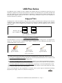
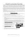
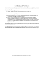
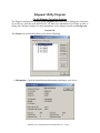
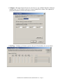
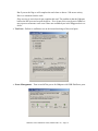
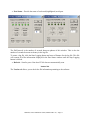
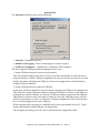
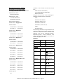
USB Plus Series
USB PLUS POWER
SOLUTIONS
Installation
Guide
Models:
Edgeport/42+
Hubport/4+
Hubport/4c+
Hubport/PCI+
Hubport/PCI+ LP
www.digi.com
Table of Contents
USB Plus Series ................................................................... 1
Edgeport/42+........................................................................ 1
Hubport/4+ and Hubport/4c+ ................................................ 2
Hubport/PCI+ and Hubport/PCI+ LP..................................... 3
Driver Installation.................................................................. 4
USB Plus Series Interface .................................................... 6
The Edgeport Utility Program ............................................... 7
Understanding Hubs........................................................... 13
Regulatory & Other Information.......................................... 14
USB Plus Series
The USB Plus Series of products are fully compliant with standard USB ports. The PlusPower ports allow for the
attachment of USB devices that draw more than 500 mA, which is the maximum power provided by standard USB
ports. This additional power enables USB PlusPower peripherals to function properly without requiring their own
individual power supplies. These ports also have a cable locking mechanism to ensure a secure connection to
downstream PlusPower peripherals.
Edgeport®/42+
The Edgeport/42+ offers four PlusPower USB ports and two RS-232 serial DB-9 ports, allowing for the connection
of PlusPower USB, standard USB, and legacy serial devices in a single box. USB Port 1 supplies 24 VDC, and Ports
2 through 4 supply 12 VDC (in addition to the standard 5 VDC available in all of the PlusPower ports as shown in
figure 1 below).
Standard 5 VDC
Type A USB Port
24 VDC key
12 VDC key
Figure 1: USB PlusPower Port Diagrams
Cabling the Edgeport/42+
Note that Windows NT 4.0 users must install the drivers before connecting their Edgeport/42+. The Edgeport/42+
operates as a self-powered hub, requiring a power supply to function. For more information about hubs, see the
“Understanding Hubs” section on page 13.
USB PlusPower
Type A Connector
Standard USB
Type A Connector
Standard USB
Type B Connector
Figure 2: USB Connectors
1) Connect one end of the power supply* into the back of the Edgeport/42+ and the other end into an AC outlet.
2a) To connect your Edgeport/42+ to a PC, plug the type A end of a standard USB cable into one of the PC’s USB
ports and the Type B end into the back of the Edgeport/42+.
2b) To connect a standard USB device to the Edgeport/42+, plug the Type A end of the USB cable into the lower
section of one of the Edgeport/42+ USB PlusPower slots and the Type B end of the USB cable into the peripheral.
2c) To connect a PlusPower USB device to your Edgeport/42+, plug the type A end of the USB PlusPower cable
into one of the Edgeport/42+ USB PlusPower slots (ensuring that the voltage key on the cable matches the voltage
key of the port) and the other end into the peripheral.
*Power for the Edgeport/42+ may be supplied by a UL Listed “Class 2” power supply or Information Technology
Equipment power supply, rated 24 V dc, and not exceeding 4.0 A.
+
-
USB Plus Series Installation Guide (90000410 Rev. E) – Page 1
Hubport®/4+ and Hubport/4c+
Hubport/4+ and Hubport/4c+ (compact) are externally powered hubs that connect to a standard USB upstream port.
They both offer four downstream USB PlusPower ports that are compatible with both standard USB and PlusPower
USB devices. Port 1 supplies 24 VDC, and Ports 2 through 4 supply 12 VDC (in addition to the standard 5 VDC
available all of the PlusPower ports as shown in figure 1 on page 1). All of the ports are keyed for their specific
power rating and have cable locking mechanisms to ensure a secure connection to PlusPower peripheral devices. See
Figure 1 on page 1 for a diagram of the different keys.
Cabling the Hubport/4+ and Hubport/4c+
Note that Windows NT 4.0 users must install the drivers before connecting these Hubports. For a diagram of USB
cable end types, see Figure 2 on page 1.
1) Connect one end of the power supply* into the back of your Hubport and the other end into an AC outlet.
2a) To connect your Hubport to a PC, plug the Type A end of a standard USB cable into one of the PC’s USB
ports and Type B end into the back of the Hubport.
2b) To connect a standard USB device to your Hubport, plug the Type A end of the USB cable into the lower
section of one of the Hubport USB PlusPower slots and the Type B end of the USB cable into the peripheral.
2c) To connect a PlusPower USB device to your Hubport, plug the Type A end of the USB PlusPower cable into
one of the Hubport USB PlusPower slots (ensuring that the voltage key on the cable matches the voltage key of
the port) and the other end into the peripheral.
*Power for the Hubport/4+ and Hubport/4c+ may be supplied by a UL Listed “Class 2” power supply or
Information Technology Equipment power supply, rated 24 VDC, and not exceeding 4.0 A.
USB Plus Series Installation Guide (90000410 Rev. E) – Page 2
Hubport/PCI+ and Hubport/PCI+ LP (Low Profile)
Hubport/PCI+ is a USB 2.0 full size expansion card with powered USB technology. The Hubport/PCI+ card is
available in two versions. The externally powered card utilizes a 24 volt external power supply. The internally
powered card utilizes power balancing technology to provide maximum power to 12 volt and 24-volt peripherals
without exhausting the PC’s 5 or 12 volt power. Port 1 supplies 24 VDC, and Ports 2 through 4 supply 12 VDC (in
addition to the standard 5 VDC available in all of the PlusPower ports as shown in figure 1 on page 1).
The Hubport/PCI+ LP product refers to two USB 2.0 low profile expansion cards with powered USB technology:
the active card, which has 3 ports, and the passive card, which has 1 port. The active card is managed and the
passive card can be either managed or not managed, depending on how it is installed (as described in step 6 below).
“USB Plus Series Interface” on page 6 and “Edgeport Utility Program” on page 7 describe in detail management of
the Hubport/PCI+.
All of the USB ports have cable locking mechanisms to ensure a secure connection to PlusPower peripheral devices.
These ports are also keyed to ensure that they can be connected only to a USB plug designed for their specific power
rating. See Figure 1 on page 1 for a diagram of the different keys.
Installing the Hubport/PCI+
1) Discharge any static electricity from your body by touching a grounded metal object (such as the exposed
metal parts on the back of your computer) before handling your Hubport/PCI+ card.
2) Turn off power to the computer and disconnect the power cord.
3) Open the computer cabinet. See your computer documentation for specific instructions, if needed.
4) Locate an unused PCI expansion slot and remove the expansion slot cover. Save the slot cover screw for use
in Step 5.
5) Insert the USB PlusPower adapter in the PCI expansion slot. Press the adapter firmly into the slot until it
clicks into place. Replace the slot cover screw. When installed properly, the adapter should be level with the
expansion slot.
6) Attach an available hard drive power cable into the connector on the back of the Hubport/PCI+ card or
Hubport/PCI+ LP active card (if using separately or together) or the Hubport/PCI+ LP passive card (only if
using separately). If none are available, you may need to purchase a standard Y-connector.
7) For the Hubport/PCI+ LP passive card only: This board has no controller and must be connected to another
controller: either to the Hubport/PCI+ LP active card (managed) OR via USB to the PC (unmanaged).
a) Managed: Plug the ribbon cable on the active card
into the receptacle on the passive card, making sure that
the notches match. (See picture at right.)
b) Unmanaged: Plug one end of a USB cable in to the
card and the other end into the PC.
8) For externally powered cards only, plug the 24 volt
power supply into the card and tighten the locking
screw.
9) Close the computer cabinet and reattach the power cord.
10) After restarting your computer you may continue with driver installation.
USB Plus Series Installation Guide (90000410 Rev. E) – Page 3
Driver Installation
For Windows XP and 2003 Server Users
Note: If your computer is connected to the internet, the latest Microsoft certified drivers will be automatically
downloaded from the Microsoft driver update server.
1) You must be logged into an account with administrator privileges.
2) Insert the “Edgeport Driver” CD version 3.60 or above into your CD-ROM drive.
3) When the Found New Hardware Wizard appears click Next, and the drivers will be automatically installed
from the CD
For Windows 2000
1) You must be logged into an account with administrator privileges
2) Insert the “Edgeport Driver” CD version 3.60 or above into your CD-ROM drive.
3) When the Found New Hardware Wizard appears, select Install from a list or specific location
(Advanced) and click Next.
4) Select Search for a suitable driver for my device and click Next.
5) Select Specify a location and click Next.
6) Type in <CD drive letter>:\Win2k and click OK.
7) Confirm that Windows is pointing to <CD drive letter>:\Win2k. Then click Next.
Note: Drivers installed from the CD have received “Designed for Windows 2000” certification. Drivers
downloaded from our web site may be pending certification. If so, Windows 2000 will display a warning: Digital
Signature Not Found. Click Yes to continue with driver installation. If you click No you will need to contact Digi
International Technical Support before installing your USB Plus Series product.
8) Windows will then finish installing the driver files.
9) Click Finish to complete the driver installation.
Installation is complete when no more dialogs appear. Your new COM port(s), numbered sequentially following the
existing ports in your system, is/are ready.
For Windows 98, and Me Users
1) Insert the "Edgeport Driver" CD version 3.60 or above into your CD-ROM drive.
2) After connecting the USB cable, the Add New Hardware Wizard appears. Click Next.
3) Select Search for the best driver for your device and click Next.
4) Select Specify a location and type in <CD drive letter>:\Win98. Then click Next.
5) Confirm that Windows is pointing to <CD drive letter>:\Win98. Click Next. Windows will then copy
over the driver files.
6) Click Finish to complete the driver installation.
Installation is complete when no more dialogs appear. Your new COM port(s), numbered sequentially following the
existing ports in your system, is/are ready.
USB Plus Series Installation Guide (90000410 Rev. E) – Page 4
For Windows NT 4.0 Users
Because Microsoft does not support USB in NT4.0, Inside Out Networks supplies a set of USB drivers that will be
installed along with the necessary Edgeport drivers. NOTE: You must install the drivers using an account that has
administrative privileges.
To install the USB stack and Edgeport drivers:
1) Insert the “Edgeport Driver” CD version 3.60 or above into your CD-ROM drive.
2) When the welcome dialog appears, click the Install Driver button.
Once the driver installation program has begun, follow the on screen instructions.
3a) If you are installing drivers for the first time: An Information dialog informs you that the installation was
successful. After clicking OK, the installation is complete.
3b) If you are replacing existing Edgeport drivers: Follow the on-screen instructions. Note that, before
beginning the installation of the drivers, all applications with open ports must be closed and all USB
devices unplugged. If you close all the applications and unplug all the USB devices, then you will not need
to reboot for the new drivers to take effect immediately. If any applications are left open or USB devices
plugged in, you may choose to abort the installation or to continue and be required to reboot before the
upgrade can take effect.
Note that because Windows NT 4.0 is not Plug-and-Play, you will not see a pop-up dialog box indicating that new
hardware has been found. You may verify correct installation with the Edgeport Utility (see page 7) or the USB
Status Utility (as described below).
The USB Status Utility (Viewer) can be accessed by clicking the USB icon in your system tray or by clicking on
Start, Programs, Inside Out Networks Utilities, USB Status Utility. This utility lists all the USB devices installed
on your PC and provides other relevant information for each device. You may also use this utility to create a log file.
USB Plus Series Installation Guide (90000410 Rev. E) – Page 5
USB Plus Series Interface
(for Hubport/4c+ and the managed Hubport/PCI+ and Hubport/PCI+ LP cards)
The USB Plus Series products present themselves to a user application by way of a virtual serial port. This serial
port is named as all standard serial ports in the form of COMx where x is a number between 1 and 255. The number
assignment can be configured using the Edgeport configuration utility. (See the “Edgeport Utility Program” section
for more information about using this utility.)
There are two ways to manage the power on these devices: You can either use an ASCII command interface to send
commands to the Power Management COM port, as described in this section, or you can use the Edgeport Utility
program (see page 7).
All ASCII commands sent to the device must be terminated with a carriage return character <CR>.
The format of the response sent from the USB Plus Series product to the application is an ASCII printable character
string terminated by a <CR>.
Other response strings generated by the USB Plus Series product include Invalid Command <CR>.
Command Set
Command
Description
Return Value
?<CR>
Tells about the command set available for the USB
Plus Series.
as described herein
I<CR>
Displays port type.
Power Management Port<CR>
Eh<CR>
Enables port power as defined by the hexadecimal
value of h.
OK<CR>
Dh<CR>
Disables port power as defined by the hexadecimal
value of h
OK<CR>
S<CR>
Returns port power status in hexadecimal.
h<CR>
Changes to the configuration are saved in the device. If the device is reset, it will be initialized with the saved
values.
Commands D and E each have a bit-mapped hexadecimal argument indicating which port, or ports, should be
enabled or disabled. The bit map will have the least significant bit representing port 1, the next least significant bit
representing port 2, etc. For example, to enable port 1, the user would send the string 'E1<CR>'. To disable both
port 1 and port 3, the user would send 'D5<CR>'. To enable ports 1, 2, and 4, the user would send 'EB<CR>'.
The response to the S command will be a hexadecimal bit-mapped value indicating the current powered state of the
four ports, with a 1 indicating power enabled, 0 indicating power disabled.
As with the D and E commands, the bit map for the S response will have the least significant bit representing port 1,
etc. For example, a response of '4<CR>' would indicate that port 3 is power enabled, and ports 1, 2, and 4 are power
disabled. A response of 'E<CR>' would say that ports 2, 3 and 4 are enabled, and port 1 is disabled. A response of
'0<CR>' would indicate that all ports are power disabled.
USB Plus Series Installation Guide (90000410 Rev. E) – Page 6
Edgeport Utility Program
For All Windows Operating Systems
The Edgeport configuration utility program (edgeport.exe) allows you to manage the serial ports
of your device. Note that with Windows NT you must have administrative privileges in order to
change the COM port settings. For more information, see the Support section at www.digi.com.
General Tab
The General tab in this utility allows you to do the following:
• Information - Check the manufacturing information pertaining to your device.
Digi International
USB Plus Series Installation Guide (90000410 Rev. E) – Page 7
• Configure - Reassign the physical port on your device to any available Windows COM port
number from 1 to 255 and give your device a user friendly Device Name. This capability is
particularly helpful if you have more than one device.
• Port Flags - Configure performance options and special functionality on a per-port basis.
USB Plus Series Installation Guide (90000410 Rev. E) – Page 8
Low Latency:
Normally the UART will interrupt when the receiver has been idle for 4 character times.
(For example 4ms at 9600) As long as data is being received the UART will continue to
buffer them until its internal FIFO is full (~56 bytes). This flag causes the Edgeport to
poll the RX FIFO for received bytes. If any bytes are available they will be sent to the
driver without any delay.
Remap Baud: (All operating systems)
Setting the baud rate to 1200 baud will result in 230400 baud
Ignore Flush: (Windows NT/2K/XP)
If an application sends IRP_MJ_FLUSH_BUFFERS it will be ignored.
Excerpt from Microsoft documentation:
Drivers of devices with internal caches for data and drivers that maintain internal buffers
for data must handle this request.
When Sent
Receipt of a flush request indicates that the driver should flush the device's cache or its
internal buffer, or, possibly, should discard the data in its internal buffer.
Operation
The driver transfers any data currently cached in the device or held in the driver's internal
buffer(s) before completing the flush request. The driver of an input-only device that
buffers data internally might simply discard the currently buffered device data before
completing the flush IRP, depending on the nature of its device.
Fast Writes: (All operating systems)
When an application sends a write to the driver, by default the Edgeport driver will wait
until all data has been transmitted out of the Edgeport device before completing the write.
When the Fast Writes flag is set, we complete the write even if data is still buffered in the
driver and the Edgeport device.
Fast Reads:
This flag is used when an application requires that a read complete immediately. In the
read immediate case, the Edgeport driver will send a request to the Edgeport device
asking for any buffered data to be sent up. This buffered data will be included when the
read completes. If this flag is set, the driver will not query the Edgeport device for
additional data.
Timer Logic: (Windows 9x only)
If application uses PortSetReadCallBack(), the notification routine will only be called
when the number of bytes in the receive buffer is greater then the RX trigger. The
Microsoft serial VxD also implements a timer that will trigger and call the notification
routine if some amount of data is available in the RX buffer but no new data has been
received for ~200ms (receiver is no longer active).
We do not enable this behavior by default because of the nature of Edgeport buffering.
USB Plus Series Installation Guide (90000410 Rev. E) – Page 9
But if you set the flag we will complete the read when we detect ~200 ms no activity.
Here is a comment from the code:
If the receiver is active then do not complete this read. The problem is that the Edgeport
buffers the RX bytes and we poll the driver. If we do not receive any bytes in 200ms we
may report an erroneous event even if there are available bytes in the Edgeport device or
driver.
• Test Ports - Perform a confidence test on the internal workings of the serial ports.
• Power Management – Turn on and off the power for Hubports with USB PlusPower ports
USB Plus Series Installation Guide (90000410 Rev. E) – Page 10
• Port Status – Provide the status of a selected (highlighted) serial port.
The Poll Interval is the number of seconds between updates of this window. This is also the
number of seconds between each entry in the log file.
To create a log file, click the Start Logging button and enter a filename for the log file. This file
will contain all of the information displayed in the Port Status window until the Stop Logging
button is clicked.
• Refresh – Scan for ports. Note that NT 4.0 does not automatically scan.
Version Tab
The Version tab allows you to check the file information pertaining to the software.
USB Plus Series Installation Guide (90000410 Rev. E) – Page 11
Advanced Tab
The Advanced tab allows you to do the following:
• Uninstall – Uninstall the drivers.
• Enable Event Logging – Place event messages in system event log.
• COM Port Assignment – Configure how COM ports will be assigned.
The driver supports COM port number assignment in two ways:
1. Assign COM ports based on converter serial number.
This is the default setting. In this mode, the driver uses the serial number of each converter to
uniquely identify it, and the COM port assignments for a given converter are based on its serial
number. No matter which physical USB port a converter is plugged into, it will maintain its
assigned COM port numbers.
2. Assign COM ports based on physical USB port.
In this mode, the driver identifies a converter based on the physical USB port it is plugged into.
This effectively assigns COM port numbers to physical USB ports. No matter which converter
is plugged into a given USB port, it will use the COM port numbers assigned to that USB port.
This permits a converter to be to be replaced with a new unit, and, although the new unit has a
different serial number, it will receive the same COM port assignments as the old unit because
they were both plugged into the same USB port.
When using this mode, converters are identified not by their serial number, but by a 2-7 digit
number that identifies which USB port it is plugged into.
After changing this setting, you will need to reboot before the change takes effect.
USB Plus Series Installation Guide (90000410 Rev. E) – Page 12
Understanding Hubs
Hubs, critical components in the USB architecture, are wiring concentrators that enable the
attachment of multiple devices, thus converting a single attachment point into multiple
attachment points. USB architecture allows a cascaded multiple hub configuration with certain
power limitations (explained later in this section). See figure 1.
PC
Host
Hubpo rt
Edgeport
Edgeport
Hu bp ort
Ed geport
bu s-powered hub
joystick
scanner
mou se
Figure 1: Examp le of a Typica l Hub Con figuration
Each hub has an upstream port, connecting to the host, and multiple downstream ports,
connecting to downstream devices, possibly including other hubs. A hub can detect attachment
and detachment of downstream devices and enable and monitor the distribution of the power to
downstream devices via their integral hardware and the operating system.
Each USB device reports its power requirements to the operating system, which then enables and
disables the device as a function of its power requirements and the amount of available power.
High powered devices typically need to be connected to a self-powered hub, such as the
Hubport, which obtains power from its external power supply and provides up to 500 mA for
each standard USB port. Only low powered devices, such as a mouse, can be connected to a buspowered hub, which obtains power from its upstream host and provides up to 100 mA for each
standard USB port.
Due to the limited available power for bus-powered hubs, cascading two bus-powered hubs is an
illegal topology, and devices connected to the second hub will not function. USB specifications
limit the connection of a bus-powered hub to a self-powered hub or host only.
According to the USB Specification, the maximum limit of hubs cascaded in series cannot
exceed five. In other words, you may have a maximum of five hubs between any device and the
host. This does NOT mean that the maximum number of hubs in a system is five. Indeed, up to
seven hubs can be connected parallel at any given level. You must tally both external and
embedded hubs when counting downstream hubs.
USB Plus Series Installation Guide (90000410 Rev. E) – Page 13
Regulatory & Other Information
© 2006 Digi, Digi International, the Digi logo,
the Digi Connectware logo, Inside Out Networks
and its logo, Edgeport, and Hubport are either
trademarks or registered trademarks of Digi
International, Inc. in the United States and/or
other countries. All other trademarks are the
property of their respective holders.
Information in this documentation is subject to
change without notice and does not represent a
commitment on the part of Digi International.
Digi International provides this document “as
is,” without warranty of any kind, either
expressed or implied, including, but not limited
to, the particular purpose. Digi International may
make improvements and/or changes to this
documentation or to the product(s) and/or
program(s) described in this documentation at
any time.
Digi International assumes no responsibility of
any
errors,
technical
inaccuracies,
or
typographical errors that may appear in this
documentation, nor liability for any damages
arising out of its use. Changes are made
periodically to the information herein; these
changes may be incorporated in new editions of
the publication.
For U.S. Government use:
Any provision of this document and associated
computer programs to the U.S. Government is
with “Restricted Rights.” Use, duplication, or
disclosure by the government is subject to the
restrictions set forth in, subparagraph (c) (1) (ii)
of the Rights in Technical Data and Computer
Software clause of DFARS 52.277-7013.
For non-U.S. Government use:
These programs are supplied under a license.
They may be used, disclosed, and/or copied only
as supplied under such license agreement. Any
copy must contain the above copyright notice
and restricted rights notice. Use, copying, and/or
disclosure of the programs is strictly prohibited
unless otherwise provided for in the license
agreement.
Federal Communications Commission
(FCC) Regulatory Information (USA only)
This equipment has been tested and found to
comply with the limits for a Class B digital
device, pursuant to Part 15 of the FCC Rules.
These limits are designed to provide reasonable
protection against harmful interference in a
residential
installation.
This
equipment
generates, uses, and can radiate radio frequency
energy and, if not installed and used in
accordance with the instructions, may cause
harmful interference to radio communications.
However, there is no guarantee that interference
will not occur in a particular installation. If this
equipment does cause harmful interference to
radio or television reception, which can be
determined by turning the equipment off and on,
the user is encouraged to correct the interference
by one or more of the following measures:
• Reorient or relocate the receiving antenna.
• Increase the separation between the
equipment and the receiver.
• Connect the equipment into an outlet that is
on a circuit different from the receiver.
• Consult the dealer or an experienced
radio/TV technician for help.
Warning: The connection of a non-shielded
interface cable to this equipment will invalidate
the FCC Certification for this device.
FCC Regulation - Part 15
Declaration of Conformity (DoC)
This device complies with the requirements of
the Code of Federal Regulations listed below:
FCC Title 47 CFR, Part 15 Class B for a digital
device.
Operation is subject to the following two
conditions:
This device may not cause harmful interference,
and
This device must accept any interference
received, including interference that may cause
undesired operation.
Department of Communication (DOC)
Notice (Canada only)
This Class B digital apparatus meets the
requirements of the Canadian InterferenceCausing Equipment Regulations.
Cet appareil numérique de la Classe B respecte
toutes les exigences du Règlement sur le matériel
brouiller du Canada.
USB Plus Series Installation Guide (90000410 Rev. E) – Page 14
European Community - CE Mark
Declaration of Conformity (DOC)
conforms to the relevant EU Directives listed
here:
According to ISO/IEC Guide 22 and EN 45014
EMC Directive 2004/108/EC|
Low Voltage Directive 2006/95/EC
R&TTE 1999/5/EC
Manufacturer’s Name:
Inside Out Networks
Manufacturer’s Addr.:
using the relevant section of the following EU
standards and other normative documents:
EMC:
11001 Bren Road East
Minnetonka, MN 55343
EN55022 Class B(2006)
declares that the product
EN55024 (1998+A1,A2)
Product Name: Edgeport/42+
EN61000-3-2(2000+A2)
Model Numbers:
EN61000-3-3(1995+A1,A2)
North America
International
Safety:
301-1001-42
301-2001-42
EN 60950 (2001)
Product Name: Hubport/4+
Model Numbers:
North America
International
301-1010-14
301-2010-14
Product Name: Hubport/4c+
EN55022
Model Numbers:
North America
International
301-1157-01
301-1157-01
Product Name: Hubport/PCI+
North America
International
301-1149-01
301-1149-01
301-1150-01
301-1150-01
301-1151-01
301-2151-01
301-9007-01
301-9207-01
Product Name: Hubport/ PCI+ LP
Model Numbers:
North America
International
301-1170-01
301-1170-01
301-1171-01
301-1171-01
301-1172-01
301-2172-01
301-1173-01
301-1173-01
All
Test
Specification
EN55022
Requirement
Radiated Emissions
—
Class B
Conducted
Emissions
CISPR 22
Class B
Test
Specification
EN55024
Requirement
Electrostatic
Discharge
EN61000-4-2
+2,+4 kV direct contact
+2,+4 kV and +8kV air
(insulated surfaces)
+2,+4 kV(HCP&VCP)
indirect
Radiated Immunity
EN61000-4-3
3 V/m, 80Mhz-1000Mhz,
amp mod 1kHz sine wave
at 80%
Electrical Fast
Transient Burst
EN61000-4-4
+0.5kV,+ 1kV (A/C)
+0..5kV (I/O)
Surge
EN61000-4-5
+0.5kV,+ 1kV 1kV
Conducted
Immunity
EN61000-4-6
3Vrms, .150Mhz to
80Mhz, amp mod. 1kHz
wave at 80%
Magnetic Immunity
EN61000-4-8
1 A/m Not Applicable
Voltage Dips &
Interrupts
EN61000-4-11
>95%10ms, 30%@500ms
& >95%@5sec reduction
at rated voltage
EN 55024
Model Numbers:
Product Options:
The following summarizes the specifications and
requirements for EN55024:1998, EN55022:1998
Class B & CISPR 22 Class B emission and
immunity tests and the EN61000-3-2(2000),
EN61000-3-3(1995) current harmonics and
voltage variation tests. Actual test levels are
listed in the appropriate tables.
USB Plus Series Installation Guide (90000410 Rev. E) – Page 15
Test
Specification
Requirement
UL/CSA Safety Information
Limits for
harmonic current
emission
EN61000-3-2
Class A
This device complies with the requirements of
following safety standards below:
Test
Specification
Requirement
Limitation of
voltage
fluctuation and
flicker
EN61000-3-3
-
UL 1950, 3rd edition
CSA No. 950
Quality Manager
Austin, Texas
July 2006
European Contact
Digi International
Joseph-von-Fraunhofer Str. 23
44227 Dortmund, GERMANY
49-231-9747-0
China RoHS statement:
The Table of Toxic and Hazardous Substances/Elements and their Content shall apply to any product
covered by this manual and labeled with the following symbol:
The Table of Toxic and Hazardous Substances/Elements and their Content
as required by China’s Management Methods for the Control of Pollution from Electronic Information Products
Part Name
(部件名称)
301-1002-08
Lead
(Pb)
(铅)
X
Toxic and Hazardous Substances or Elements
(有毒有害物
有毒有害物质
或元素)
有毒有害物
质或元素
Hexavalent Polybrominated Polybrominated
Mercury Cadmium Chromium
biphenyls
diphenyl ethers
(Cr (VI))
(PBB)
(PBDE)
(Hg)
(Cd)
(汞)
O
(镉)
O
(六价铬)
O
(多溴联苯)
O
(多溴二苯醚)
O
O: Indicates that this toxic or hazardous substance contained in all of the homogeneous materials for this
part is below the limit requirement in SJ/T 11363-2006.
表示该有毒有害物质在该部件所有均质材料中的含量均在SJ/T11363-2006 标准规定的限量要求以下.
X: Indicates that this toxic or hazardous substance contained in at least one of the homogeneous
materials used for this part is above the limit requirement in SJ/T 11363-2006.
示该有毒有害物质至少在该部件的某一均质材料中的含量超出SJ/T11363-2006 标准规定的限量要求.
USB Plus Series Installation Guide (90000410 Rev. E) – Page 16
Digi International
11001 Bren Road East
Minnetonka, MN 55343
[email protected]
www.digi.com
Corporate
Headquarters:
952-912-3444
877-912-3444
Fax: 952-912-4952
Digi Europe: +49-231-9747-0
Digi Hong Kong: +852-2833-1008
Digi North America: 877-912-3444
USB Plus Series Installation Guide (90000410 Rev. E) – Page 17