1
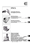
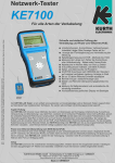
BEDIENUNGSANLEITUNG KE301 - KE401 - KE501 - KE701 / 702
®
Probe 310/410 ( Berührungsloser Empfänger)
Die PROBE ist ein berührungslos arbeitender Prüflautsprecher, der die von EasyTest gesendeten Signale empfängt und hörbar macht. Die grüne Signalstärke - LED mit
Filterfunktion zeigt das präzise 1kHz Signal vom EasyTest an. Störende Signale, z.B. 50 Hz oder die Harmonischen davon werden ausgefiltert. Die Probe 410 verfügt
zusätzlich über eine rote LED, mit der eine ISDN UK0 Leitung gefunden werden kann. Damit kann einfach an z.B. Verteilern eine aktive ISDN UK0- Leitung detektiert werden.
Eine Taschenlampen - Funktion mit reinweißem Licht garantiert eine eindeutige Farberkennung der Adernkennzeichnungen in dunklen Verteilern. Die Prüfspitze der PROBE
besteht aus faserverstärktem, leitfähigem Kunststoff mit Bajonettverschluss zum einfachen Wechseln vor Ort ohne Öffnen des Gerätes . Am unteren Ende der PROBE
befindet sich eine Anschlußbuchse für einen optional erhältlichen Ohrhörer (Art.-Nr. 49600), mit dem Signale aus größeren Entfernungen (bis zu 150 cm) noch gut verfolgt
werden können. Die Probe wird durch Drücken der Tasten High oder Low eingeschaltet. Die Position High ist die empfindlichste Stufe zum Suchen schwacher Signale. In
Position Low wird z.B. das gefundene Adernpaar oder Kabel präzisiert.
07/10 Product design and specifications subject to change without notice. All trademarks belong to their respective companies.
Stand 07/10 - Druckfehler, Irrtümer und technische Änderungen vorbehalten. Alle eingetragenen Warenzeichen und Marken sind, auch wenn nicht ausdrücklich gekennzeichnet, Eigentum der jeweiligen Inhaber.
EasyTest 300 - 720 ( Tonsender )
Spannungsfestigkeit bei versehentlichem Anschluss an Überspannung:
MODUS CONT (Widerstandsprüfung) 240 V AC - Alle Geräte
MODUS TONE (Suchton)
120V AC - KE3xx, KE4xx
500V AC - KE5xx, KE7xx
EasyTest wird durch die Taste ON/OFF ein- und ausgeschaltet.
Einschalten : Nach Drücken der Taste ON/OFF ist zur Einschaltbestätigung ein Ton hörbar (nur KE7xx ) und die ALT- und SOLID LEDs leuchten kurz auf. Für alle anderen
Versionen werden je nach Stellung des dreistufigen Schiebeschalters folgende LEDs als Einschalt - Information genutzt. Stellung:
TONE = ALT- LED blinkt
DATA = Data- LED leuchtet schwach grün
CONT = CONT- LED blinkt kurz
EasyTest schaltet nach 30 Minuten automatisch aus. Wenn es länger benötigt werden sollte, so wird, nachdem das Gerät eingeschaltet ist, die ON/OFF Taste innerhalb 1
Sekunde zweimal betätigt. Es ertönt wieder ein kurzer Bestätigungston, daß der Timeout - Override- Modus aktiviert wurde. Zusätzlich blinkt die SOLID- LED kurz. Wenn im
Tone Modus die Funktion SOLID gewählt ist, übernimmt diese Funktion die ALT- LED.
Ausschalten: Drücken der ON/OFF Taste länger als 1,5 Sekunden. Es ertönt der Abschaltton (nur KE7xx), die ALT- und SOLID LEDs leuchten kurz auf und das Gerät schaltet
aus.
Schnelle Anzeige von Leitungszustand bei analogen Telefonleitungen oder Prüfung von Spannungsquellen auf digitalen Leitungen, Linien von Alarmanlagen und
vielem mehr. Auf einen Blick erkennbar dargestellt wird der Zustand der analogen Telefon - Anschlußleitung nach Einschalten und dem Einstecken von EasyTest in die
Anschlußdose der Telefonleitung. Dies geschieht z. B. direkt mit dem RJ11 - Stecker (nicht KE5xx), mit dem als Option lieferbaren TAE - Adapter oder durch einfaches
Anklemmen an die Adern mit den Krokodilklemmen.
Freie Leitung – Speisespannung bis zu 70 Volt DC, LED POL leuchtet hell. Rot a/b - vertauscht, grün richtig gepolt, A-Ader oder minus auf roter Klemme. EasyTest zeigt
mit roter LED zusätzlich an ob die Spannung 90V an den Prüfleitungen übersteigt. Diese Information kann auch zur Identifikation der Spannung am ISDN U-Interface
benutzt werden. Ab 100 V wird zusätzlich beim KE7xx ein Alarmton zugeschaltet zur Warnung vor hoher Spannung auf der Linie.
Belegte Leitung – Speisespannung zwischen 10 und 20 Volt DC. LED POL leuchtet dunkel. Rot a/b vertauscht, grün richtig gepolt. Sinnvoll z.B. an einem Verteiler um zu
prüfen, ob die Leitung belegt ist oder nicht. Rufwechselspannung wird durch zusätzlich aufleuchtende rote oder grüne POL - LED angezeigt. Bei reiner Wechselspannung
leuchtet die POL - LED orange. Grundsätzlich kann mit EasyTest jede Art von Spannungsquelle auf Polarität, Art der Spannung und deren ungefähre Höhe geprüft werden.
1. Modus TONE - Suchton
Nach dem Einschalten im Modus TONE startet Easytest mit der ALTernierenden Konsequenz . EasyTest verfügt über vier Suchfrequenzen. Die Auswahl ist denkbar einfach.
Durch kurzes Drücken (<2 sec) der Taste SOLID wird eine Suchfrequenz mit exakt 1 kHz gesendet. Wird die Taste länger als 2 sec gedrückt so wird eine Suchfrequenz von 2,9
kHz erzeugt.
Durch Drücken der Taste ALT (<2 sec) werden die Frequenzen 880 Hz/1 kHz abwechselnd gesendet. Durch Drücken länger als 2 sec. wird auf die Frequenzkombination 1,9
kHz/2,6 kHz umgeschaltet. Die hohen Suchfrequenzen haben zwei Vorteile: Erstens ist das menschliche Ohr im Bereich 2600 Hz mit am empfindlichsten, zweitens sind diese
beiden Frequenzen außerhalb der Signalisierungsfrequenzen von Telefonsystemen. Die LEDs rechts von den Tasten zeigen an welcher Suchton aktiviert ist. Dies ist auch aus
der Entfernung erkennbar. Das Suchsignal kann ohne zu stören auf aktive (Spannungsführende) Telekommunikations- und Datenleitungen eingespeist werden. KE4xx und
KE7xx sind für Datensignale hochohmig, deshalb ist es möglich, auf aktive Telefonleitungen mit ISDN- und ADSL Systemen Suchsignale ohne Datenstörungen zu senden.
KE4xx reduziert zusätzlich durch Sinussignale die mögliche Störung.
A. Suche von Kabeln
Für die Kabelsuche – auch unter Putz – wird EasyTest mit der schwarzen Prüfschnur an die Erde und mit der roten Prüfschnur an eine Einzelader oder ein Adernpaar
angeklemmt. Jetzt die Suchfrequenz auswählen. Der gewählte Ton wird gesendet und kann berührungslos mit der PROBE aus bis zu 60 cm Distanz vom Kabel verfolgt
werden. Ist ein Kurzschluss vorhanden, so wird ähnlich wie bei unterbrochenen Doppeladern der Ton in das Kabel gesendet und alle Adern damit beaufschlagt, dies jedoch nur
bis max. 200 Meter. Das Kabel wird mit der PROBE gesucht. Diese wird durch Drücken und gedrückt halten der Taste LOW oder HIGH eingeschaltet. Um ein Signal aus
größerer Entfernung oder ein schwaches Signal zu finden wird die Taste HIGH gedrückt. Bei großen Kabelbündeln am Verteiler oder in einer Pritsche wird die PROBE flach
über das Bündel bei gleichzeitig gedrückter „HIGH“-Taste bewegt. Nachdem die Kabel mit dem stärksten Signal ermittelt sind, wird durch Betätigen der „LOW“-Taste das
gesuchte Kabel millimetergenau definiert. Der höchste Signalpegel ist immer über dem gesuchten Kabel. Bei der Suche von abgeschirmten Kabeln wird das rote Prüfkabel an
den Schirm und das schwarze an Erde (z. B. Schutzleiter, Wasserleitung) angeschlossen. Ist kein Schirm vorhanden, werden zwei Drähte (KEIN Paar!) im Kabel angeschlossen. Wenn der Schirm geerdet ist, muss er beidseitig freigeschaltet werden. Bei Fernmelde- oder Datenkabeln mit verdrillten Adern dürfen keine verdrillten Adern
angeschlossen werden !
B. Suche von Adernpaaren (Doppeladern)
Bei der Suche von Doppeladern und dem Herausfinden von Überziehungen wird je eine Prüfschnur von EasyTest an je eine Ader eines Adernpaares angeschlossen. Hier
muss es das verdrillte Paar sein. Das kann automatisch durch Anstecken an eine Anschlussdose oder durch Anklemmen am offenen Kabelende geschehen. Mit der PROBE
und gedrückt gehaltener “HIGH” Taste wird die Doppelader am anderen Ende oder an jedem Verteiler gefunden. Zum genauen Finden wird die „LOW“-Taste gedrückt und
damit exakt das Adernpaar mit dem stärksten Signal herausgefunden. Wenn das Paar über die gesamte Strecke verdrillt ist, so wird exakt dieses Paar gefunden. Befindet sich
auf der Strecke z.B. eine Adernunterbrechung oder eine Vertauschung einer einzelnen Ader (Split) so werden am Verteiler mehrere Adern mit dem Suchsignal gefunden. Das
ist dann der Hinweis auf einen Fehler in der Verkabelung. Es muss nun zurückgegangen werden, um den Fehler einzugrenzen. Bei offenen Kabelenden wird ähnlich verfahren,
die Adern werden aufgefächert und die PROBE mit gedrückter “LOW” - Taste flach darüber bewegt. Wird nun die Prüfspitze der PROBE über die Adern geführt, bekommt man
über der ersten Ader des richtigen Adernpaares einen hohen Pegel angezeigt, in der Mitte ein Minimum und über der zweiten Ader wieder einen hohen Pegel. Damit ist die
Doppelader eindeutig identifiziert. Wenn kein Minimum zu finden ist, ist es entweder das falsche Adernpaar oder es liegt ein Kabelfehler vor, hervorgerufen z. B. durch eine
Unterbrechung, Vertauschung, oder eine Überziehung (ein sogenanntes “Split Pair”). EasyTest sendet die Suchfrequenz mit ca. 12 dB auch in Leitungen mit einem
Abschlusswiderstand bis hinunter zu 50 Ohm. Damit kann mit KE3xx/4xx/5xx/7xx auch auf speisespannungsführende Telefon - oder Datenleitungen ein Suchton gesendet
werden. Die maximale Kabellänge beträgt 15 km (unbelastet).
2. Modus CONT - Durchgangsprüfung / Widerstandsprüfung
Wenn der Schiebeschalter an der rechten Seite von KE3xx/4xx/5xx auf CONT steht, ist der Durchgangstest - Modus eingeschaltet. Es wird eine Prüfspannung an die
Prüfleitung angelegt. Damit lässt sich auf einfache Art der Durchgang von Leitungen, Kontakten oder Widerständen bis zu 100 kOhm prüfen. Die grüne LED CONT blinkt kurz
wenn der Test aktiviert wurde oder wenn der Widerstand an den Prüfklemmen über 100 kOhm beträgt. Sie leuchtet, je nach Wert des Widerstandes von hell bis dunkel auf.
Damit ist eine ungefähre Bestimmung des Widerstandes möglich. Bei der EDV - Verkabelung lässt sich so einfach und ohne Störungen feststellen ob die Leitung “gepatcht” ist.
Das KE7xx hat zusätzlich noch einen Tonprüfmodus eingebaut. Dieser ersetzt einen sog. “Piepser”. Dabei ist die Frequenz des Tones abhängig vom Widerstand. Bei 0 Ohm
(Kurzschluss) sind ca. 3 kHz und bei ca. 100 kOhm 500 Hz hörbar. Damit lassen sich Widerstandswerte abschätzen. Aber auch Kondensatoren und andere Bauteile können so
einfach geprüft werden.
3. Modus DATA - Link - Blink Funktion
Wenn der Schiebeschalter bei KE4xx und KE7xx auf dieser Position steht leuchtet die DATA LED schwach grün zur Indikation. Zum Prüfen wird das zusätzliche gelbe RJ45
Prüfkabel verwendet. Eingesteckt in einen Datenport leuchtet die grüne DATA - LED hell im Takt des NLP, wenn der Datenport gepatcht ist. Im 4 Sekunden Takt wird das
Normal Link Puls- Signal (NLP) gesendet. Dieses wird am EasyTest mit der LED und einer Tonfolge angezeigt. Bei den gängigsten HUB, Switches oder Router wird in
demselben Takt die zu dem Port gehörende LINK - LED ein- und ausgeschaltet. Damit kann der zur Datendose zugehörige Port festgestellt werden.
Low Batt - Batteriespannungsüberwachung
Wenn bei eingeschaltetem Gerät die Batterie einen Spannungswert von ca. 6V unterschreitet, blinkt die SOL - LED alle 60 Sekunden drei mal kurz zur Indikation auf, beim
KE7xx ertönt zusätzlich ein Warnton. Im TONE Modus bei aktivierter SOL Frequenz blinkt übernimmt diese Funktion die ALT - LED. Bei Erreichen von 5V schaltet EasyTest
automatisch ab.
BEDIENUNGSANLEITUNG KE301 - KE401 - KE501 - KE701 / 702
55-56
GERM
(0)97
ANY
13
sse
+49
Fax
erstra
55-0
gen
21-97 Daiml
Pfullin
(0)71
93
+49
D-727
R
Tel.
H
NIC
RT
TRO
KU
ELEC
gen
Pfullin
Fax
erstra
55-0
(0)71
93
+49
D-727
R
Tel.
H
Erde
Ground
R
}
NIC
RT
C
O
N
T
Bis zu 15 Km
up to 15 Km
TRO
KU
ELEC
Bis zu 60 cm
up to 60 cm
ON
OFF
OFF
EASYTEST
ANY
55-56
GERM
POL
(0)97
+49
13
CONT
ALT
The pair with the strongest
signal is the right one.
Known
Pair
OFF
OFF
SOLID
Daiml
sse
C
O
N
T
21-97
55-56
GERM
(0)97
ANY
e 13
+49
rstrass
Fax
55-0
gen
21-97 Daimle
Pfullin
93
+49
Tel.
D-727
KU
RT
TRO
NIC
H
R
(0)71
Bekanntes
Paar
ON
Kein Signal (geringes)
No signal (low)
SOLID
CONT
ALT
POL
R
EASYTEST
SOLID/ALT
Prüfen von Spannung und Polarität, bei Telefon, Sprechanlage, Alarmanlage usw, Verfolgen des Kabelweges, auch unter Putz (bis zu 30 cm !)
Checking for voltage and polarity in Telephone systems, Intercom, Burglar Alarm. Trace the cable path also for cable inside a wall. (Up to 30 cm)
2. TELECOM
Einstecken und Spannung/ Polarität wird angezeigt.
In Modus CONT wird Kurzschluss angezeigt
In Modus SOLID/ALT kann das Kabel/ das
Adernpaar gesucht und bis zur Anlage verfolgt werden.
ANY
GERM 55-56
e
13
(0)97
rstrass +49
Fax
gen
93
R
Daimle
55-0
Pfullin 21-97
(0)71
D-727 +49
H Tel.
RT NIC
TRO
KU
ELEC
Verfolgung des Kabels
siehe 1.2
Trace of the cable
see 1.2
R
93
gen
e
13
Schnelles Überprüfen von
Rangierungen und Finden
von Fehlern.
Fast and easy check and
trace of bridges.
ANY
(0)97
GERM 55-56
rstrass +49
Fax
Daimle
55-0
Pfullin 21-97
(0)71
D-727 +49
H Tel.
RT NIC
TRO
KU
ELEC
Not KE5xx
Nicht KE5xx
ON
C
O
N
T
OFF
After plug in you will see voltage and polarity.
In mode CONT check for Continuity
In mode SOLID/ALT trace of the cable path thru
walls, distribution boxes - to the Pabx or central office.
OFF
CONT
SOLID
POL
ALT
R
EASYTEST
- PABX
- Central Office
- Alarm System
Durchgangsprüfung Im Modus CONT, einfaches Feststellen, ob der Computer - Anschluss durchgeschaltet ( “gepatcht” ) ist oder nicht. Ist er durchgeschaltet, leuchtet
die LED CONT. Ist er nicht durchgeschaltet, schnelles Finden des richtigen Auslasses am Patchfeld im Modus SOLID/ALT mit der PROBE. Ist er gepatcht wird mit KE4xx/7xx ein
LINK - Puls gesendet. Es blinkt dann die zugehörige LINK - LED am HUB oder Router.
Continuity, easy to find out if an network outlet is patched or not. If he is patched, the CONT- LED will light. If it is not patched, select SOLID/ALT and find with the PROBE easy and
fast the right port. If the Port is active, KE4xx/7xx will transmit a LINK - Pulse. The corresponding LINK-LED on the HUB or Router will start blinking to indicate the right port.
Computer Anschluss
Einfach über die Buchsen fahren,
Office Outlet
sofort die Richtige gefunden !
The easiest way to find the right jack!
ANY
GERM 55-56
e
13
(0)97
rstrass +49
Fax
gen
93
R
Daimle
55-0
Pfullin 21-97
(0)71
D-727 +49
93
gen
e
13
ANY
(0)97
GERM 55-56
Verfolgung des Kabels
siehe 1.2
Trace of the cable
see 1.2
C
O
N
T
CONT
POL
ALT
rstrass +49
Fax
Daimle
55-0
Pfullin 21-97
(0)71
D-727 +49
ON
OFF
OFF
SOLID
Patch Paneel
R
H Tel.
RT NIC
TRO
KU
ELEC
3. DATA
H Tel.
RT NIC
TRO
KU
ELEC
R
EASYTEST
Funktioniert bei den gängigsten Geräten - works with the most popular units
Network Server
Finden von Kurzschlüssen und Unterbrechungen in Starkstromverkabelungen. Verfolgen des Kabels bis zur Unterbrechung.
Locates shorts and opens in high voltage wiring. Trace of the cable
path to the open.
Bei Starkstrominstallationen kann der Kabelweg über alle Verteiler bis hin zur
Sicherung verfolgt werden.
In High Voltage installations is it possible to trace the cable path from the outlet up
to the specified fuse.
No Tone
Freie Adern Kurzschliessen
Connect open wires together
Verfolgung des Kabels
Trace of the cable
ANY
6
GERM 55-5
13
sse
gen
93
R
lerstra Fax
0
Daim
755-
(0)97
+49
Pfullin 21-9
(0)71
D-727 +49
H Tel.
RT NIC
TRO
KU
ELEC
R
93
gen
ANY
(0)97
GERM 55-5
+49
13
Fax
sse
lerstra
0
Daim
755-
Pfullin 21-9
(0)71
D-727 +49
6
R
93
gen
ANY
(0)97
GERM 55-5
+49
13
Fax
sse
lerstra
0
Daim
755-
Pfullin 21-9
(0)71
D-727 +49
H Tel.
RT NIC
TRO
KU
ELEC
6
4. ELEKTRO
Open
Tone
H Tel.
RT NIC
TRO
KU
ELEC
ON
ON
C
O
N
T
C
O
N
T
OFF
OFF
OFF
OFF
SOLID
ALT
CONT
SOLID
POL
ALT
CONT
POL
Sicherungskasten
Fusebox
R
R
EASYTEST
EASYTEST
SOLID/ALT
SOLID/ALT
ACHTUNG ! An Starkstrominstallationen nur spannungsfrei arbeiten ! -- CAUTION ! Working on High Voltage Installations only mains free !
5. SPLIT
07/10 Product design and specifications subject to change without notice. All trademarks belong to their respective companies.
Kabellänge bis 15 Km
Cable length up to 15 Km
Das Paar mit dem stärksten
Signal ist das gesuchte Paar.
SOLID/ALT
Stand 07/10 - Druckfehler, Irrtümer und technische Änderungen vorbehalten. Alle eingetragenen Warenzeichen und Marken sind, auch wenn nicht ausdrücklich gekennzeichnet, Eigentum der jeweiligen Inhaber.
1.2 Suche von Kabeln aller Art
Locating of all kind of cables
1.1 Suche von Doppeladern
Pair identifying
ELEC
1. GENERELL
®
Ein häufig vorkommender und mit normalen Prüfgeräten nur schwer einzugrenzenderFehler ist die Adernüberziehung, genannt Split-pair. Die dabei auftretenden
Störungen, z.B. bei ISDN oder anderen Installationen sind unklar, hervorgerufen durch erhöhtes Nebensprechen oder Übersprechen. Diese Fehler lassen sich leicht
mit EasyTest und Probe eingrenzen und beseitigen.
It happens very often that someone made a splice and used a wrong wire. Means that he is using a wire from one pair together with a wire from another pair. This
fault is called “split pair”. Every high quality service on this pair will have problems. In analog systems for example a modem will have no speed, in ISDN, you will have
undefined breakdowns, and so on. This occures only because this pair have a lot of noise produced from crosstalk. With EASYTEST and PROBE easy to find
and solve the problem.
Y
trasse
R
1
ON
C
O
N
T
OFF
OFF
SOLID
ALT
CONT
POL
A
B
3
2
1
TH
KURRONIC
GERMAN
-56
(0)9755
3
2
R
D-72793
KURTH
ELECTRONIC
R
EASYTEST
13
n Daimlers Fax +49
Pfullinge
-9755-0
D-72793
(0)7121
+49
Tel.
ELECT
4
Pfullingen
Tel. +49
13 GERMANY
Daimlerstrasse
(0)9755-56
Fax +49
(0)7121-9755-0
Einfaches Feststellen des angeschlossenen Paares.
Easy location of the connected pair
Das durch die Überziehung verknüpfte Paar wird ebenso einfach
gefunden.
The corresponding pair is also easy
located.
4
KURTH ELECTRONIC GmbH • Im Scherbental 5 • D-72800 Eningen u.A. • GERMANY
Tel. +49(0)7121-97 55-0 • Fax +49(0)7121-97 55 56
www.kurthelectronic.de • e-mail: [email protected]
Made in GERMANY
USER MANUAL
KE301 - KE401 - KE501 - KE701 / 702
®
Probe 310/410 (Non-contact tone receiver)
The PROBE is a receiver and amplifier that detects tracing signals from senders like the EasyTest and makes them audible over the built-in speaker. The green signal
level LED lights when the key 1 kHz tone from EasyTest is detected among the signals on line. Interfering signals such as 50 Hz power hum and its harmonics will not
trigger the green LED. The Probe 410 has a second, red LED that lights when an ISDN Basic Rate signal is detected. This allows an active ISDN BRI (UK0) line to be
detected in places like distribution boxes.
US Version of Probe KE310: Green signal level LED detect Frequency 577.5 Hz, rather than 1 kHz.
07/10 Product design and specifications subject to change without notice. All trademarks belong to their respective companies.
Stand 07/10 - Druckfehler, Irrtümer und technische Änderungen vorbehalten. Alle eingetragenen Warenzeichen und Marken sind, auch wenn nicht ausdrücklich gekennzeichnet, Eigentum der jeweiligen Inhaber.
A flashlight function with a pure white light allows the identifying colors of the wires to be seen clearly in dark distribution boxes. The test tip of the PROBE consists of
fiber-reinforced conductive plastic with a secure bayonet lock that allows easy on-site exchange without opening the unit. At the rear end of the PROBE there is a
connection socket for an optional earphone (item no. 49600). The Probe is turned on by pressing the High or Low buttons. The High position is the most sensitive level
for tracing weak signals. Low position is used to identify the specific pair or wire needed.
EasyTest 300 - 720 (tone generator and line tester)
Maximum withstand voltage – not for test use:
CONT MODE (resistance test)
240V AC - All devices
TONE MODE (tracing tone)
120V AC - KE3xx, KE4xx
500V AC - KE5xx, KE7xx
The EasyTest is turned on and off by pressing the ON/OFF button.
After pressing the ON/OFF button, an audible tone is emitted to confirm that the device has been turned on (only the KE7xx), and the ALT and SOLID LEDs light
briefly. For all other versions, the LEDs depend on the position of the three-position sliding switch:
TONE = ALT LED flashes
DATA = Data LED shines weak green
CONT = CONT LED flashes briefly
The EasyTest automatically shuts off after 30 minutes. To disable auto shut-off, press the ON/OFF button twice within one second after the device is turned on. A short
confirmation tone (only KE7xx) will sound to indicate that the timeout override mode was activated. In addition, the SOLID LED flashes briefly. If you are in the SOLID
tone mode, it is the ALT LED that flashes briefly. To Shut the Unit Off: Press the ON/OFF button for more than 1.5 seconds. The shut-off tone sounds (only KE7xx), the
ALT and SOLID LEDs light briefly, and the unit turns off.
Quick display of the status of analog telephone lines, testing for voltage on digital lines or alarm system wires, and much more. the status of analog telephone lines is
easily checked by turning on the EasyTest and inserting it into wall jack. This is easily done, , using the RJ11 connector (not included with the KE5xx) though it can
also be done using the optional TAE adapter, breakout adapter or by simply clipping the device onto the wires using alligator clips. Idle telephone lines have voltages
up to 70V DC, and the POL LED shines brightly when the tester is connected. Red indicates a/b (T/R) inverted, green indicates correct polarity, i.e., a-wire, ring or
negative on the red terminal. EasyTest indicates with the red warning LED when the voltage on the line is greater than 90V. This information can also be used to
identify the voltage at the ISDN U-interface. (92 – 96 V DC)
Starting at 100V, an alarm tone is generated by the KE7xx to warn that the voltage is too high on the line and can be dangerous.
Busy analoge telephone lines have voltages between 10 and 20V DC, and the POL LED is dim when the tester is connected. Red indicates a/b (T/R) inverted, green
indicates correct polarity. This is useful for determining if the line is busy or not in a distribution box. The POL LED is orange when pure AC ringing voltage is present.
With the EasyTest, any kind of voltage source can be checked for polarity, type of voltage and its approximate level. The latest EasyTest is high impedance in any
mode, meaning EasyTest draws no line current to drive the POL LEDs.
1. TONE mode (send tracing tone)
When switching to TONE mode, the EasyTest starts as default with alternating or warbling tone frequencies. The EasyTest has six easily selected tracing tone
frequencies. Briefly press the SOLID button (less than 2 seconds) to transmit a trace frequency at precisely 1 kHz. If you press the button for more than 2 seconds, a
trace frequency of 2.9 kHz is generated. Additional pressing of 2 seconds switches to 577.5 Hz.
Press the ALT button for less than 2 seconds to send alternating frequencies of 880 Hz/1 kHz. Press it for more than 2 seconds to switch to an alternating frequency of
1.9 kHz/2.6 kHz. Another 2 seconds switches to a intermittent 577.5 kHz tone. The high trace frequencies have two advantages. First, the human ear is the most
sensitive at 2,600Hz and second, these two frequencies lie outside the signaling frequency range of telephone systems. The LEDs to the right of the buttons indicate
the activated trace tone and can be seen from a distance. The trace signal can be injected without interfering with active (voltage present) telecommunications and
data lines. The KE4xx and KE7xx are high-impedance for data signals, which makes it possible to transmit trace signals on active telephone lines with ISDN and
ADSL systems without causing interference. The KE4xx further reduces possible interference by sending sinusoidal signals.
A. Tracing cables
When tracing cables and wires, even within a wall, clip the black test lead of the EasyTest to ground and the red test lead to a single wire or a wire pair. Select the trace
frequency. The selected tone is transmitted and can be tracked without contact using the PROBE for up to 60cm from the cable. Tone will be transmitted even on
shorted pairs to a maximum of 200 m. The PROBE is used to trace the cable. This is done by pressing and holding the LOW or HIGH button. To locate a signal at a
greater distance or to trace a weak signal, press the HIGH button. In the case of large cable bundles in a distribution box or rack, the PROBE is moved flat above the
bundle while pressing the HIGH button. After the cables are located using the strongest signal, press the LOW button to find the precise location of the desired cable.
The highest signal is always above the desired cable. When tracing shielded cables, connect the red test lead to the shielding and the black test lead to ground (such
as a protective conductor or water line). If there is no shielding, connect across two different pairs within the cable. If the shielding is grounded, it must be isolated at
both ends. Do not connect across pairs carrying Voice and pairs carrying Data.
B. Tracing twisted pairs
To trace specific twisted pairs and identify split pairs, connect one EasyTest test lead to one wire and connect the other test lead to the other wire. The wires must be
from the same twisted pair. This can be done by connecting to a wall jack or by clipping to the open cable end. While holding down the HIGH button, use the PROBE to
find the wire pair at the other end or at each distribution box. To determine the precise location, hold down the LOW button and find the wire pair with the strongest
signal. If the pair is twisted over the entire length, this specific pair will be found. If a wire is disconnected along the length or if the pair changes to a single wire (split),
several wires in the distribution box will carry the trace signal. This indicates a fault in the wiring. You now have to go back and locate the fault. When the cable ends are
open, use a similar procedure; spread apart the wires and move the PROBE flat over them while holding down the LOW button. When the test tip of the PROBE is
guided across the wires, the first wire of the correct wire pair displays a high level, a minimum level is displayed in the middle, and the second wire again displays a
high level. This distinctly identifies the wire pair. If you cannot find a minimum level, either it is the wrong wire pair, or there is a cable fault that may have been caused
by an interruption, crossed or split pair. The EasyTest transmits the trace frequency at approximately 12 dBm in lines with a terminal resistance that can be as low as
50 ohm. With the KE3xx/4xx/5xx/7xx, you can transmit on energized telephone or data lines. The maximum cable length for detection is 15 km (no load).
2. CONT mode - continuity check/resistance check
Turn on the continuity test mode by setting the sliding switch on the right side of the KE3xx/4xx/5xx to CONT. This applies a voltage to the tested line making it possible
to sense line continuity, shorts or resistors up to 100 kOhm. The green LED CONT briefly flashes when the test is activated or when the resistance at the test terminals
is above 100 kOhm. Depending on the level of the resistance, LED brightness will vary from light to dark. This allows the resistance to be estimated. This is a good way
to check if data cables are patched to terminating equipment. The KE7xx replaces a beeper with a variable tone resistance check. The frequency of the tone depends
on the resistance. At 0 ohm (short), a tone of approximately 3 kHz is audible, and at 100 kOhm, a tone of 500 Hz can be heard. This allows you to estimate the
resistance. It is also possible to test capacitors and other components this way.
3. DATA mode link - blink function
When the sliding switch of the KE4xx and KE7xx is set to Data, the DATA LED shines dimmly green to indicate the mode is on. The yellow RJ45 test cable is used for
testing. When it is inserted in a data port, the green DATA LED pulses brightly in sync with the generated NLP when the data port is patched to terminating equipment
like a hub or switch. The normal link pulse signal (NLP) is transmitted in four second cycles. This is displayed on the EasyTest with the green DATA LED and tone
sequence (7xx only). With conventional hubs, switches or routers, the link LED belonging to the port is turned on and off in the same cycle. This allows you to identify
equipment port you are connected to.
Daten - Data
KE301 - KE401 - KE501 - KE701 / 702
®
07/10 Product design and specifications subject to change without notice. All trademarks belong to their respective companies.
Stand 07/10 - Druckfehler, Irrtümer und technische Änderungen vorbehalten. Alle eingetragenen Warenzeichen und Marken sind, auch wenn nicht ausdrücklich gekennzeichnet, Eigentum der jeweiligen Inhaber.
Housing/Gehäuse:
Heavy duty water resistant housing made
from ABS, elastomeric silicon rubber push
button switches./ Stabiles und schlagfestes
wetterbeständiges ABS-Gehäuse mit Silikon
Betätigungstasten
Clip and Modular Test Leads/ Prüfschnüre:
KE3xx/KE4xx
10” (25cm) durable wire leads with solid
alligator clips and one with a special
long RJ11 modular plug
25cm lange Prüfschnüre aus flexiblem PVC mit
Krokodilklemmen, eine Prüfleitung mit RJ11
Modularstecker
KE7xx
10” (25cm) durable wire leads with solid banana
plugs and one with a special
long RJ11/45 universal modular plug with latch
protection
25cm lange Prüfschnüre aus flexiblem PVC mit
Bananenstecker, eine Prüfleitung mit RJ11/45
universal Modularstecker mit latch protection
KE4xx/KE7xx
Additional 10” (25 cm) modular cable with RJ45 plug
Zusätzliches Modularkabel mit RJ45 Stecker
KE5xx
15” (39 cm) extra strong test leads with CATIII 4mm
Banana Plug and full insulated Crocodile clips
protected CATIII / 1000V.
Extra starke Prüfschnüre mit CATIII Bananenstecker
und voll isolierten Krokodilklemmen. Geschützt nach
CATII bis 1000V.
KE4xx/KE7xx special functions
LINK- blink function for active Data Ports 10/100 Mb
KE4xx/KE7xx zusätzliche Funktion
LINK- blink funktion zur identifizierung von aktiven
Datenports in 10 und 100 Mb Systemen.
Over Voltage Protection
Überspannungsschutz
KE3xx/KE4xx/KE5xx/KE7xx
Over voltage protected in all mode up to 120V AC /
DC
Überspannungsgeschützt in allen Modi bis 120V AC
/ DC Wechselspannung
KE5xx/KE7xx
Over voltage protected up to 500V AC / DC in tone
modus. Red Alarm LED lights up if voltage on test
leads exceeds appr. 90V. Alarm Tone if Voltage
exceeds 100 V (KE7xx)
Überspannungsgeschützt bis zu 500V AC / DC im
Ton- Modus. Die rote ALARM - LED leuchtet bei
einer Spannung an den Prüfschnüren ab ca. 90V
auf. Bei Spannung über 100V ertönt zusätzlich ein
Alarmton ( KE7xx)
CONT - Modus
KE3xx/KE4xx/KE5xx
Green LED. Changing brightness Bright from 0 - 100
kOhm. Detection up to 100 Kohm loop resistance.
Voltage protection up to 120V AC / DC.
Grüne LED. Zunehmende Helligkeit von 0 - 100
kOhm. Sichtbar bis zu 100kOhm Widerstand.
Spannungsgeschützt bis 120V AC / DC.
KE7xx
Additional resistance depending beeper. At short 3
kHz audible. At appr. 100kOhm 500Hz audible.
Voltage protection up to 120V AC / DC.
Zusätzlicher widerstandsabhängiger Prüfton . Bei
Kurzschluss 3 kHz hörbar. Bei ca. 100kOhm ca.
500Hz hörbar. Spannungsgeschützt bis 120V AC /
DC .
Six Frequencies Selectable / Sechs Frequenzen
wählbar:
1. SOLID: 1000 Hz
2. ALT: 1000/800 Hz
3. SOLID: 2600 Hz
4. ALT: 2600/1900 Hz
5. SOLID: 577,5 Hz
6. ALT: 577,5 Hz intermittant
Accuracie / Genauigkeit < +/- 0,5%
KE3xx / KE5xx / KE7xx Output w. new battery
Output Signal 9V pp square wave
Ausgangssignal 9V ss Rechteck
10 dBm into 600 Ohm
9 dBm into 150 Ohm
7,5 dBm into 75 Ohm
Tone over shorted pair up to 200 m. (Inhouse)
Ton auf kurzgeschlossener Ader bis 200m
KE4xx output w. new battery
Output signal 13V pp sine wave
Ausgangssignal 13V ss Sinus
7 dBm into 600 Ohm
3 dBm into 150 Ohm
0 dBm into 75 Ohm
Tone over shorted pair up to 200 m. (Inhouse)
Ton auf kurzgeschlossener Ader bis 200m
Low Batt indicator by flashing LED plus warning
tone (KE7xx)
Low Batt - Anzeige durch blinkende LED und
Alarmton (KE7xx)
Auto shut Off after 30 minutes
Automatische Abschaltung nach 30 Minuten
Auto shut Off override with LED Indication
Deaktivierung der Abschaltung mit LED Anzeige
Trace Distance to Cable/Wire /Suchentfernung
zum Kabel:
Up to 23” (60cm) / Bis zu 60 cm
Trace Cable Length/ maximale Kabellänge:
Up to 10mls (no load)/ Bis zu 16Km ohne Belastung
Other Specifications / weitere
Leistungsmerkmale:
Gold Plated Contacts
Goldbeschichtete Kontakte
ON - Indication by LED
Einschaltkontrolle mit LED
Alternating blinking LED
ALT mit blinkender LED
Solid - steady LED
SOLID mit LED stehender LED
Strain Relief
Zugentlastung der Prüfschnüre
Separate Battery Compartment
Getrenntes Batteriefach
Battery / Batterie:
9V Alkaline, >200 hrs battery life
9V Batterie >200 Stunden Lebensdauer
Dimensions / Abmessungen:
2.68” x 3.75” x 1.0” (68 x 96 x 25 mm)
Weight / Gewicht:
2.4 oz (150g) Without Battery
150g ohne Batterie
PROBE 310 / 410 / 510
Housing / Gehäuse:
Heavy duty water resistant housing made
from ABS. / Solides, schlagfestes und wasserfestes
ABS - Gehäuse
Specifications / Leistungsmerkmale:
High impedance carbon fiber tip
Hochohmige Prüfspitze aus Kohlefaserverstärktem
Kunststoff
Tip easy field replaceable by bayonet lock
Prüfspitze einfach auswechselbar durch BajonnettVerschluss
Signal strength LED with filter function
Signalstärke LED mit Filterfunktion
Torch light function with bright white LED
Taschenlampenfunktion mit heller weisser LED
3.5 mm Earphone Jack
3,5 mm Kopfhörerbuchse
Gold Plated Contacts
Goldbeschichtete Kontakte
Separate Battery Compartment
Getrenntes Batteriefach
Battery / Batterie:
9V Alkaline, >100 hrs battery life
9V Batterie >100 Stunden Lebensdauer
Dimensions / Abmessungen:
8.7” x 1.57” / 1.34” x 0.98”
220 x 40 / 34 x 25 mm)
Weight / Gewicht:
1.28 oz (80g) Without Battery
80g ohne Batterie
Probe 410 - ISDN indication (not US- Version)
Additional indicator LED will light up if ISDN signal
is present on a distribution block or wiring.
GARANTIE
KURTH ELECTRONIC GmbH übernimmt die Garantie nach den jeweiligen aktuellen allgemeinen Geschäftsbedingungen. Die AGB`s der Fa. Kurth Electronic werden
ausdrücklich anerkannt. Die jeweilig aktuelle Fassung befindet sich auf dem Geschäftspapier oder ist auf der Web-Page von Kurth Electronic downloadbar.
Für von uns mitgelieferte fremde Fabrikate übernehmen wir nur die Garantie, welche die betreffenden Lieferanten uns gegenüber gewähren. Eine weitergehende Haftung,
insbesondere für Vermögensschäden, ist ausgeschlossen.
Zu reparierende Gegenstände, auch innerhalb unserer Garantieverpflichtung, sind franko 72800 Eningen anzuliefern. Vor der Rücksendung von Geräten zur Reparatur, auch
bei Garantiereparaturen, muß eine Rücksende-Autorisations Nummer ("RA") beantragt werden. Rücksendungen ohne diese Nummer werden von uns nicht angenommen,
ebenso unfrei eingesandte Lieferungen. Die RA kann mit FAX oder via E-Mail erfragt werden. Unsere Garantiepflicht erlischt automatisch, wenn der Auftraggeber Änderungen
oder Reparaturen vornimmt oder durch Dritte vornehmen läßt. Rücksendeadresse siehe unten.
WARRANTY
KURTH ELECTRONIC GmbH warrants that its products shall be free of any defects in parts or workmanship, for a period of 12 months from the
date of manufacture, if used under kurth Electronic´s operating specifications.
THIS IS THE ONLY WARRANTY MADE BY KURTH ELECTRONIC AND IS MADE EXPRESSLY IN LIEU OF ALL OTHER WARRANTIES EXPRESS OR IMPLIED,
INCLUDING BUT NOT LIMITED TO ANY IMPLIED WARRANTIES OF MERCHANTABILITY OR FITNESS FOR ANY PARTICULAR PURPOSE.
Should any parts or workmanship prove defective, Kurth Electronic will repair with "not used” or reconditioned parts, or replace the product, at Kurth Electronic' option, at no
cost to the buyer except for shipping costs from the Buyer's location to Kurth' location. This is the buyer's SOLE AND EXCLUSIVE REMEDY under the agreement all incidental
or consequential damages shall be excluded. This warranty does not extend to products which have been subjected to neglect, accident or improper use, nor to units which
have been altered or repaired by other than authorized Kurth Electronic personnel. Non-Warranty. Out-of-warranty maintenance, service, or repair of products is available from
Kurth Electronic on a time and materials basis. In addition, Kurth offers for sale some replacement components. Kurth Electronic recommends that out-of-warranty service
and repair of electronic products be completed at its Kurth facility or authorized representative.
Return or Repair of Equipment
Before any product is returned, including for warranty service, a Return Authorization ("RA”) number must be obtained from the Customer Service Department by Fax or E-mail
at:
[email protected]
If the RA number is not clearly marked on the shipping label, the package will not be accepted by Kurth. All authorized returns must be shipped, with shipping charges prepaid,
F.O.B destination, and addressed as follows:
KURTH ELECTRONIC GmbH • Im Scherbental 5 • D-72800 Eningen u.A. • Germany
Tel. +49(0)7121/97 55-0 • Fax: +49(0)7121/97 55 56 • www.kurthelectronic.de
[email protected]