1
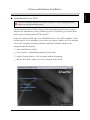
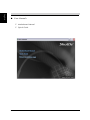
XPC User Guide For the : SH67H3/SH67H7 Shuttle® XPC Installation Guide Copyright ©2010 by Shuttle® Inc. All Rights Reserved. No part of this publication may be reproduced, transcribed, stored in a retrieval system, translated into any language, or transmitted in any form or by any means such as electronic, mechanical, magnetic, optical, chemical, photocopy, manual, or otherwise, without prior written permission from Shuttle® Inc. Other brands and product names used herein are for identification purposes only and may be trademarks of their respective owners. Disclaimer Shuttle® Inc. shall not be liable for any incidental or consequential damages resulting from the performance or use of this product. Shuttle® Inc. makes no representation or warranty regarding the contents of this manual. Information in this manual had been carefully checked for accuracy;however, no guarantee is given as to the correctness of the contents. For continuing product improvement, Shuttle® Inc. reserves the right to revise the manual or make changes to the specifications of this product at any time without notice and obligation to any person or entity regarding such change. The information contained in this manual is provided for general use by customers. This device complies to Part 15 of the FCC Rules. Operation is subject to the following two conditions: 1.This device may not cause harmful interference. 2.This device must withstand any background interference including those that may cause undesired operation. Trademarks Shuttle is a registered trademark of Shuttle Inc. Intel and Pentium are registered trademarks of Intel Corporation. PS/2 is a registered trademark of IBM Corporation. AWARD is a registered trademark of Award Software Inc. Microsoft and Windows are registered trademarks of Microsoft Corporation. General Notice Other brand and product names used herein are for identification purposes only and may be trademarks of their respective owners. Safety Information Read the following precautions before setting up a Shuttle XPC. CAUTION Incorrectly replacing the battery may damage this computer. Replace only with the same or equivalent as recommended by Shuttle. Disposal of used batteries according to the manufacturer's instructions. Laser compliance statement The optical disc drive in this server is a laser product. The drive's classification label is lacated on the drive. CLASS 1 LASER PRODUCT CAUTION:NVISIBLE LASER RADIATION WHEN OPEN. AVOID EXPOSURE TO BEAM. Installation Notices Do not place this device underneath heavy loads or in an unstable position. Do not use or expose this device around magnetic fields as magnetic interference may affect the performance of the device. Do not expose this device to high levels of direct sunlight, highhumidity or wet conditions. Do not block the air vents to this device or impede the airflow in any way. TABLE OF CONTENTS Driver and Software Installation...................................................................................1 Mainboard Driver DVD ............................................................................................1 User Manuals ..................................................................................................2 Appendix......................................................................................................................3 Starting BIOS...........................................................................................................3 BIOS Setup Menu....................................................................................................3 Main Setup ......................................................................................................5 Advanced ........................................................................................................6 ACPI Settings..........................................................................................7 CPU Configuration..................................................................................8 SATA Configuration.................................................................................9 Intel IGD Configuration.......................................................................... 11 Super IO Configuration.........................................................................12 H/W Monitor..........................................................................................15 Voltage Configuration............................................................................16 Chipset................................................................................................. 18 Boot . ....................................................................................................19 Security ........................................................................................................ 20 Save & Exit ....................................................................................................22 English Driver and Software Installation Motherboard Driver DVD The DVD contents attached in SH67H3/SH67H7 Series motherboard are subject to change without notice. The Motherboard Driver DVD contains all the motherboard drivers necessary to optimize the performance of this Shuttle Xvision in a Windows® OS. Install these drivers after installing Microsoft® Windows®. Insert the attached DVD into your DVD-ROM drive. The DVD AutoRun screen should appear. If the AutoRun screen does not appear, double click on Autorun icon in My Computer to bring up Shuttle Mainboard Software Setup screen. Navigation Bar Description : Auto Install Driver/ Utility. User Manuals - Motherboard Manual, Quick Guide. Link to Shuttle Website - Link to shuttle website homepage. Browse this DVD - Allows you to see contents of this DVD. English User Manuals Motherboard Manual Quick Guide English Appendix Starting BIOS AMIBIOS has been integrated into many motherboards for over a decade. In the past, people often referred to the AMIBIOS setup menu as BIOS, BIOS setup, or CMOS setup. American Megatrends refers to this setup as BIOS. Specifically, it is the name of the AMIBIOS8 BIOS setup utility. This chapter describes the basic navigation of the BIOS setup screens. Enter the BIOS To enter the BIOS setup screens, follow the steps below: Step1. Power on the motherboard. Step2. Press the <Delete> key on your keyboard when you see the following text prompt: Press DEL to run Setup. Step3. After you press the <Delete> key, the main BIOS setup menu displays. You can access the other setup screens from the main BIOS setup menu, such as the Chipset and Power menus. This manual describes the standard look of the BIOS setup screen. The motherboard manufacturer has the ability to change any and all of the settings described in this manual. This means that some of the options described in this manual do not exist in your motherboard's AMIBIOS. In most cases, the <Delete> key is used to invoke the BIOS setup screen. There are a few cases that other keys are used, such as <F1>,<F2>, and so on. BIOS Setup Menu The main BIOS setup menu is the first screen that you can navigate. Each main BIOS setup menu option is described in this user’s guide. The Main BIOS setup menu screen has two main frames. The left frame displays all the options that can be configured. “Grayed-out” options cannot be configured. Options is blue can be. The right frame displays the key legend. Above the key legend is an area reserved for a text message. When an option is selected in the left frame, it is highlighted in white. Often a text message will accompany it. English AMIBIOS8 has default text messages built into it. The motherboard manufacture retains the option to include, leave out, or change any of these text messages. They can also add their own text messages. Because of this, many screen shots in this manual are different from your BIOS setup screen. The BIOS setup/utility uses a key-based navigation system called hot keys. Most of the BIOS setup utility hot keys can be used at any time during the setup navigation process. These keys include <F1>, <F10>, <Enter>, <ESC>, <Arrow> keys, and so on. There is a hot key legend located in the right frame on most BIOS setup screens. Hot Key Description → Left ← Right The Left and Right <Arrow> keys allow you to select a BIOS setup screen. For example: Main screen, Advanced screen, Chipset screen, and so on. ↑ Up ↓ Down The Up and Down <Arrow> keys allow you to select an BIOS setup item or subscreen. +- Plus/Minus The Plus and Minus <Arrow> keys allow you to change the field value of a particular setup item. For example: Date and Time. Tab The <Tab> key allows you to select BIOS setup fields. F1 The <F1> key allows you to display the General Help screen. Press the <F1> key to open the General Help screen. F10 The <F10> key allows you to save any changes you have made and exit BIOS Setup. Press the <F10> key to save your changes. Press the <Enter> key to save the configuration and exit. You can also use the <Arrow> key to select Cancel and then press the <Enter> key to abort this function and return to the previous screen. ESC The <Esc> key allows you to discard any changes you have made and exit the BIOS Setup. Press the <Esc> key to exit the BIOS setup without saving your changes. Press the <Enter> key to discard changes and exit. You can also use the <Arrow> key to select Cancel and then press the <Enter> key to abort this function and return to the previous screen. Enter The <Enter> key allows you to display or change the setup option listed for a particular setup item. The <Enter> key can also allow you to display the setup subscreens. The <F8> key on your keyboard is the Fail-Safe key. It is not displayed on the BIOS key legend by default. To set the Fail-Safe settings of the BIOS, press the <F8> key on your keyboard. It is located on the upper row of a standard 101 keyboard. The Fail-Safe settings allow the motherboard to boot up with the least amount of options set. This can lessen the probability of conflicting settings. English Main Setup When you first enter the BIOS Setup Utility, you will enter the Main setup screen. You can always return to the Main setup screen by selecting the Main tab. There are two Main Setup options. They are described in this section. The Main BIOS Setup screen is shown below. System Time/System Date Use this option to change the system time and date. Highlight System Time or System Date using the <Arrow> keys. Enter new values through the keyboard. Press the <Tab> key or the <Arrow> keys to move between fields. The date must be entered in MM/DD/YY format. The time is entered in HH:MM:SS format. The time is in 24-hour format. For example, 5:30 A.M. appears as 05:30:00, and 5:30 P.M. as 17:30:00. English Advanced Select the Advanced tab from the BIOS setup screen to enter the Advanced BIOS Setup screen. You can select any of the items in the left frame of the screen, such as CPU Configuration, to go to the sub menu for that item. You can display an Advanced BIOS Setup option by highlighting it using the <Arrow> keys. All Advanced BIOS Setup options are described in this section. The Advanced BIOS Setup screen is shown below. The sub menus are described on the following pages. English ACPI Settings System ACPI Parameters. ACPI Sleep State Select the highest ACPI Sleep state the system will enter when the SUSPEND button is pressed. The choice: S1 (CPU Stop Clock) , S3(Suspend to RAM) Resume by RTC Alarm Enable or disable System wake on alarm event., When enabled, System will wake on the hr::min::sec specified. The choice: Enabled , Disabled. Wake On LAN Function Enable or disable system wake on LAN chip event. The choice: Enabled , Disabled. Wake Up By Ring Enable or disable system wake up by ring event. The choice: Enabled , Disabled. English CPU Configuration You can use this screen to select options for the CPU Configuration Settings. Use the up and down <Arrow> keys to select an item. Use the <Plus> and <Minus> keys to change the value of the selected option. A description of the selected item appears on the right side of the screen. The settings are described on the following pages. An example of the CPU Configuration screen is shown below. The CPU Configuration setup screen varies depending on the installed processor. Hyper-threding Enabled for Windows XP and Linux (OS optimized for Hyper-Threading Technology) and Disabled for other OS (OS not optimized for Hyper-Threading Technology). When Disabled only one thread per enabled core is enabled. The choice: Enabled , Disabled. Active Processor Cores Number of cores to enable in each processor package. The choice: ALl , 1. English Limit CPUID Maximum Disabled for Windows XP. The choice: Enabled , Disabled. Execute Disable Bit XD can prevent certain classes of malicious buffer overflow attacks when combined with a supporting OS (Windows Server 2003 SP1, Windows XP SP2, SuSE Linux 9.2, RedHat Enterprise 3 Update 3.) The choice: Enabled , Disabled. SATA Configuration SATA Devices Configuration. SATA Mode (1) IDE Mode. (2) AHCI Mode. (3) RAID Mode. English Intel IGD Configuration Intel IGD Function. DVMT Mode Select Select DVMT Mode used by Internal Graphics Device. The choice: Fixed Mode , DVMT Mode. DVMT / FIXED Memory Select DVMP/FIXED Mode Memory size used by internal Graphics Device. The choice: 128MB , 256MB, MaxImum. 10 English USB Configuration USB Configuration Parameters. 11 English Super IO Configuration You can use this screen to select options for the Power Management Configuration. Use the up and down <Arrow> keys to select an item. Use the <Plus> and <Minus> keys to change the value of the selected option. The settings are described on the following pages. The screen is shown below. PWR-On After PWR-Fail The system will be restore automatically to the previous power state before the power failure occurs. The choice: Enabled , Disabled. EUP Control Function Enable or disable EUP function. The choice: Enabled , Disabled. 12 English Serial Port Configuration You can use this screen to select options for the Hardware Health Configuration. Use the up and down <Arrow> keys to select an item. Use the <Plus> and <Minus> keys to change the value of the selected option. The settings are described on the following pages. The screen is shown below. Serial Port Enable or Disable Serial Port (COM) The choice: Enabled , Disabled. Cgange Settings Select an optimal setting for Super IO device. The choice: Auto, IO=3F5h; IRQ=4; IO=3F8h; IRQ=3;4,5,6,7,9,10,11,12; IO=2F8h; IRQ=3;4,5,6,7,9,10,11,12; IO=3E8h; IRQ=3;4,5,6,7,9,10,11,12; IO=2E8h; IRQ=3;4,5,6,7,9,10,11,12; 13 English CIR Controller Configuration Set Parameters of CIR Controller (CIR) CIR Controller Enable or Disable CIR Controller The choice: Enabled , Disabled. 14 English H/W Monitor Monitor hardware status. Fan Speed Control Fan Speed Control function. The choice: Smart Fan Mode , Ultra-Low Speed, Low Speed , Mid Speed , Full Speed. Power LED Brightness Power LED Brightness Control function. The choice: Auto , Low Brightness , Mid Brightness , High Brightness. 15 English Voltage Configuration You can use this screen to select options for the Hardware Health Configuration. Use the up and down <Arrow> keys to select an item. Use the <Plus> and <Minus> keys to change the value of the selected option. The settings are described on the following pages. The screen is shown below. CPU Voltage Set CPU Voltage Set Parameter. The choice: Auto , +50mv , +100mv , +150mv , +200mv , +250mv , +300mv. CPU VTT 1.05 Voltage S CPU VTT 1.05 Voltage Set Parameter. The choice: Auto , +50mv , +100mv , +150mv , +200mv , +250mv , +300mv. VDIMM Voltage Set VDIMM Voltage Set Parameter. The choice: Auto , +50mv , +100mv , +150mv , +200mv , +250mv , +300mv. 16 English SB 1.05 Voltage Set SB 1.05 Voltage Set Parameter. The choice: Auto , +50mv , +100mv , +150mv , +200mv , +250mv , +300mv. Integrated Graphic Vol Integrated Graphic Voltage Set Parameter. The choice: Auto , +50mv , +100mv , +150mv , +200mv , +250mv , +300mv. 17 English Chipset Initate Graphic Adapte Select which graphics controller to use as the primary boot device. The choice: IGD , PEG/IGD. IGD Memory IGD Share Memory Size. The choice: IGD , 32M , 64M , 128M . High Precision Timer Enabled/Disabled the High Precision Event Timer. The choice: Enabled , Disabled. 18 English Boot Select the Boot tab from the BIOS setup screen to enter the Boot BIOS Setup screen. You can select any of the items in the left frame of the screen, such as Boot Settings Configuration, to go to the sub menu for that item. You can display an Boot BIOS Setup option by highlighting it using the <Arrow> keys. All Boot BIOS Setup options are described in this section. The Boot BIOS Setup screen is shown below. The sub menus are described on the following pages. LAN Boot ROM Enabled/Disabled LAN Boot Option ROM The choice: Enabled , Disabled. BIOS Write Protect Enables/Disables BIOS Write Protect control function. The choice: Enabled , Disabled. 19 English Security Select the Security tab from the BIOS setup screen to enter the Security BIOS Setup screen. You can display an Security BIOS Setup option by highlighting it using the <Arrow> keys. All Security BIOS Setup options are described in this section. The Security Setup screen is shown below. The sub menus are documented on the following pages. ・Change Supervisor Password When this item is selected, a message box shall appear on the screen as below: Enter New Password Type a maximum of 6-digit password and press [Enter]. The password typed now will replace any previously set password from CMOS memory. You may also press [ESC] to abandon new password setting. When the Supervisor Password is set, new items Change User Password and Password Check will be added in the menu. 20 English Select Change User Password to give or to abandon password setting same as Change Supervisor Password item above. Note that Supervisor Password field allows users to enter and change the settings of the BIOS SETUP UTILITY, while User Password field only allows users to enter the BIOS SETUP UTILITY without having the authorization to make any change. The Password Check item is used to specify the type of BIOS password protection that is implemented. Settings are described below: Setup Always The password is required only when users try to access to BIOS SETUP UTILITY. The password is required every time when the Notebook is powered on or when users try to access to BIOS SETUP UTILITY. To clear a set Supervisor Password/ User Password, just press [Enter] under Change Supervisor Password/ Change User Password field when you are prompted to enter the password. Please note that when Supervisor Password has been cleared, User Password will be cleared as well. A message box will pop up confirming password will be disabled. Once the password is disabled, the system will boot and user can enter setup without entering password. 21 English Save & Exit Select the Exit tab from the BIOS setup screen to enter the Exit BIOS Setup screen. You can display an Exit BIOS Setup option by highlighting it using the <Arrow> keys. All Exit BIOS Setup options are described in this section. The Exit BIOS Setup screen is shown below. 22 English Save Changes and Exit When you have completed the system configuration changes, select this option to leave BIOS Setup and reboot the computer so the new system configuration parameters can take effect. Select "Save Changes and Exit" from the Exit menu and press <Enter>. Save Configuration Changes and Exit Now? [Ok] [Cancel] appears in the window. Select Ok to save changes and exit. Discard Changes and Exit Exit system setup without saving any changes. Discard Changes Discards changes done so far to any of the setup questions. Destore Defaults Load Optimal Default values for all the setup questions. 23