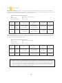
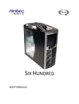
1
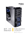
ONE
HUNDRED
WALLET-FRIENDLY
INTENSITY
USER
MANUAL
ONE HUNDRED USER MANUAL
Congratulations on your purchase of the Antec One Hundred.
Antec’s One Hundred is the gaming case that delivers high-end features at a price that won’t break the bank. Eight
expansion slots provide exceptional expandability, and can accommodate multiple video cards. A sleek painted black
interior with clean, perforated front bezel houses your components in style, while the four top USB ports with audio
in/out and handy storage tray bring convenience and accessibility to the package. Finally, the bottom PSU mount, two
included TwoCool™ fans and washable fan filter keep your system cool and quiet.
The One Hundred does not come with a power supply unit (PSU). Make sure you choose a power supply that is
compatible with your computer components and has a long enough power harness to reach your motherboard and
peripheral devices. We recommend our High Current Gamer, High Current Pro or TruePower New power supplies for
the latest ATX specification compliance, broad compatibility, and power savings capability.
At Antec, we continually refine and improve our products to ensure the highest quality. It’s possible that your new case
will differ slightly from the descriptions in this manual. This isn’t a problem; it’s simply an improvement. As of the date
of publication, all features, descriptions, and illustrations in this manual are correct.
Disclaimer
This manual is intended only as a guide for Antec’s computer enclosures. For more comprehensive
instructions on installing the motherboard and peripherals, please refer to the user’s manuals that come with
those components.
1
TABLE OF CONTENTS
SECTION 1: INTRODUCTION
1.1
1.2
1.3
Case Specifications....................................................................................................................4
Diagram ......................................................................................................................................4
Included Screws ........................................................................................................................5
HARDWARE INSTALLATION GUIDE
2.1
2.2
2.3
2.4
2.5
2.6
2.7
Setting Up...................................................................................................................................7
Power Supply Installation ........................................................................................................7
Motherboard Installation .........................................................................................................8
Internal 3.5” Device Installation ............................................................................................8
External 5.25” Device Installation .........................................................................................9
Internal 2.5” Device Installation ............................................................................................9
Cable Management ...................................................................................................................10
CONNECTING THE FRONT I/O PORTS
3.1
3.2
3.3
3.4
USB 2.0 .......................................................................................................................................12
AC’97 / HD Audio Ports ........................................................................................................12
Power Switch / Hard Disk Drive LED Connectors ..........................................................13
Rewiring Motherboard Header Connections .......................................................................13
COOLING SYSTEM
4.1
4.2
Included Fans ............................................................................................................................14
Optional Fans ............................................................................................................................15
2
SECTION 1
INTRODUCTION
3
ONE HUNDRED USER’S MANUAL
CASE SPECIFICATIONS
1.1
Case Type
Gaming Mid Tower
Color
Black
Dimensions
480 mm (H) x 198 mm (W) x 477 mm (D)
18.9” (H) x 7.8” (W) x 18.8” (D)
Weight
15.1 lbs / 6.9 kg
1 x top 140 mm TwoCool™ fan
1 x rear 120 mm TwoCool™ fan
2 x front 120 mm fans for HDDs (optional)
1 x side 120 mm fan for graphics cards (optional)
Cooling
Drive Bays
Expansion Slots
Motherboard Size
Front I/O Panel
1.2
1.
2.
3.
4.
5.
6.
7.
8.
9.
10.
11.
10 Drive Bays:
6 x internal 3.5”
3 x external 5.25”
1 x internal bottom-mounted 2.5” SSD drive
8
Mini-ITX, microATX, Standard ATX
4 x USB 2.0
AC’97 / HD Audio In and Out
DIAGRAM
1 x 140 mm top TwoCool™ fan
1 x 120 mm rear TwoCool™ fan
3 x 5.25” external drive bays
6 x 3.5” internal drive bays
1 x 2.5” SSD
Front bezel
Motherboard - Mini-ITX,
microATX or Standard ATX CPU
cutout
CPU cutout
Power supply mount
Front I/O panel
Top-front storage tray
4
INCLUDED SCREWS
1.3
A
A.
B.
C.
D.
E.
B
C
D
Motherboard standoff (10; 6 preinstalled)
Power supply / expansion slot screw (12)
Hard drive / motherboard screw (21)
Side panel fan screw (4)
Optical drive screw (12)
5
E
SECTION 2
HARDWARE
INSTALLATION
6
2.1
1.
2.
SETTING UP
Place the case upright on a flat, stable surface with
the rear of the case facing you.
Remove the side panels by first removing the
thumbscrews at the rear of the case. Then, grip each
panel at the top and bottom and slide it toward the
rear of the case until it detaches from the chassis.
Note: Do not use your fingernails to pry or lift the panels.
2.2
1.
2.
3.
POWER SUPPLY INSTALLATION
With the case upright, place the power supply on
the bottom of the case.
Push the power supply to the back of the case
and align the mounting holes.
Attach the power supply to the case with the
screws provided.
Note: Power supplies with fans on the bottom of the power supply will need to be mounted so that the
fan is facing the top of the case. The One Hundred provides mounting holes for power supplies
with standard mounting layouts to be installed upside up or upside down.
7
2.3
1.
2.
3.
4.
5.
6.
MOTHERBOARD INSTALLATION
Lay the case down, with the open
side facing up. The drive cages and
power supply should be visible.
Make sure you have the correct I/O
panel for your motherboard. If the
panel provided with the case isn’t
suitable, please contact your
motherboard manufacturer for the
correct I/O panel.
Align your motherboard with the
standoff holes and remember which
holes are lined up. Not all
motherboards will match with all the provided holes; this is normal and won’t affect its functionality.
Remove your motherboard by lifting it up.
Install standoffs as needed and put the motherboard back in.
Screw in your motherboard to the standoffs with the provided Phillips-head screws.
Note: The One Hundred comes with a CPU cutout on the motherboard tray, which will allow
you to change your CPU heatsink without removing the motherboard.
2.4
INTERNAL 3.5” DEVICE INSTALLATION
The One Hundred provides space for up to six 3.5” hard drives.
1.
2.
3.
4.
Insert your 3.5” device into the 3.5” drive cage from the rear of the case until the mounting holes align
with the screw holes in the cage.
Fasten the device in place with the provided screws.
Mount any other 3.5” HDD devices accordingly.
Connect the appropriate power and data cables to the device(s).
8
2.5
EXTERNAL 5.25” DEVICE INSTALLATION
There are three externally accessible 5.25” drive bays. To access these bays, you must first remove the front
bezel and drive bay cover:
1. Press on the three tabs pictured to the left to release the front bezel. The
bezel should swing outward, like a door.
2. Lay the bezel face down to access the drive bay covers.
3. Remove the drive bay cover as shown below by pressing on the tabs and
lifting the cover out of the bezel.
4. Slide your 5.25” device into the bay from the front of the case.
5. Secure the drive into position in the drive cage using the provided
screws.
6. Mount any other 5.25” devices accordingly.
7. Connect the appropriate power and data cables to your device(s).
2.6
INTERNAL 2.5” DEVICE INSTALLATION
At the bottom of your case, there are mounting holes designed to support
one 2.5” SSD device.
1. Locate the plastic bag labeled “For 2.5 HDD” and remove the 4
silicone grommets.
2. Install the grommets into the four holes at the base of the case at
the bottom of the drive bay area as shown. You should install them
with the thick part of the grommets facing the inside of the case.
3. Lay the One Hundred on its side, and hold the drive in place on top
of the grommets.
4. Secure the device to the case with the screws provided, tightening
the screws with your fingers first, and then the screwdriver.
5. Connect the appropriate power and data cables to your
device
9
2.7
CABLE MANAGEMENT
There is a cable management compartment behind the 3.5” drive cage. You can tuck or route excess cables in
this compartment.
1.
2.
3.
4.
Remove the right enclosure panel.
Locate the cable management compartment with cable ties located behind the walls of the 3.5” drive
cage.
Tuck or route your excess cables to the compartment. This will keep the cables from interfering with
airflow in your case and help with cooling.
Use the cable ties provided to hold them in place.
10
SECTION 3
FRONT I/O
PORTS
11
USB 2.0
3.1
Connect the front I/O panel USB cable to the USB header pin on your motherboard. Check the motherboard user’s
manual to ensure that it matches the table below:
1
2
9 10
3.2
Pin
Signal Names
Pin
Signal Names
1
USB Power 1
2
USB Power 2
3
Negative Signal 1
4
Negative Signal 2
5
Positive Signal 1
6
Positive Signal 2
7
Ground 1
8
Ground 2
9
Key (No Connection)
10
Empty Pin
AC’97 / HD AUDIO PORTS
There is an Intel® standard 10-pin AC’97 connector and an Intel® 10-pin HDA (High Definition Audio) connector
linked to the front panel of the case.
Pin
Signal Names
(HDA)
Pin
Signal Names
(AC’97)
1
MIC2 L
1
MIC In
2
AGND
2
GND
3
MIC2 R
3
MIC Power
4
AVCC
4
NC
5
FRO-R
5
Line Out (R)
6
MIC2_JD
6
Line Out (R)
7
F_IO_SEN
7
NC
8
Key (no pin)
8
Key (no pin)
9
FRO-L
9
Line Out (L)
10
LINE2_JD
10
Line Out (L)
You can connect either the AC’97 or the HDA connector, depending on your motherboard. Locate the internal audio
connectors from your motherboard or sound card and connect the corresponding audio cable. Consult your
motherboard or sound card manual for the pin-out positions. Even if your system supports both standards, only use one
connector.
12
3.3
POWER SWITCH / HARD DISK DRIVE LED CONNECTORS
Connected to your front panel are LED and switch leads for power and HDD
LED activity. Attach these to the corresponding connectors on your
motherboard. Consult your motherboard manual for specific pin header
locations. For LEDs, colored wires are positive ( + ). White or black wires are
negative ( – ). If the LED does not light up when the system is powered on, try
reversing the connection. For more information on connecting LEDs to your
motherboard, see your motherboard user’s manual.
Note: Polarity (positive and negative) does not matter for switches.
3.4
REWIRING MOTHERBOARD HEADER CONNECTIONS
There may come a time when you need to reconfigure the pin-out of a motherboard header connector.
Examples could be for your USB header, audio input header, or some other front panel connector such as the
Power Button connector.
Before performing any work, please refer to your motherboard user’s manual or your motherboard
manufacturer's website to be sure of the pin-out needed for your connector. We strongly recommend making
a notated drawing before beginning work so that you can recover if your work gets disturbed.
1.
2.
3.
Determine which wires you need to remove in order to rewire your
plug to match the USB pin-outs on your motherboard (refer to your
motherboard user’s manual). Working on one connector at a time, use
a very small flathead screwdriver or similar tool to lift up on the black
tab located beside the gold posts (squares). This will allow you to
easily slide out the pins from the USB plug.
Working carefully so as not to damage the wires, connectors, or pins,
slowly remove the pin from the connector. Repeat these steps for each
wire you need to change.
Working carefully so as not to damage the wires, connectors or pins,
slowly reinsert the pin into the correct slot of the connector then snap
closed the black tab that was lifted in step 1. Repeat these steps for
each wire you need to change.
13
4.1
INCLUDED FANS
Rear TwoCool™ Fan – There is a 120 x 25 mm TwoCool™ fan preinstalled at the rear of the case. The fan is
installed so the air will be blown out of the case. This fan comes with a two-speed switch that let you choose the
speed best suited to your need. The default fan speed setting is Low.
120 mm TwoCool™ Specifications
Size:
120 x 25 mm TwoCool™ fan
Rated Voltage:
12V
Operating Voltage:
10.8V ~ 13.2V
Speed
(RPM)
Input
Current
Airflow
Static
Pressure
Acoustic
Noise
Input
Power
High
1500
0.30A
(Max.)
1.4 m³ / min
(51.2 CFM)
1.2 mm-H 2 O
(0.05 inch-H 2 O)
27.9 dBA
3.6W
Low
900
0.18A
0.08 m³ / min
(30.1 CFM)
0.5 mm-H2O
(0.02 inch-H2O)
16.9 dBA
2.2W
Top TwoCool™ Fan – The case comes with a 140 mm top exhaust fan. The fan is installed so the air will be
blown out of the case. This fan comes with a two-speed switch that let you choose the speed best suited to your
need. The default fan speed setting is Low.
140 mm TwoCool™ Specifications
Size:
140 x 25 mm TwoCool™
Rated Voltage:
12V
10.8V ~ 13.2 V
Operating Voltage:
Speed
(RPM)
Input
Current
Airflow
Static
Pressure
Acoustic
Noise
Input
Power
High
1200
0.3A
(Max.)
1.7 m³ / min
(58.9 CFM)
0.8 mm-H2O
(0.03 inch-H2O)
26.0 dBA
3.6W
Low
800
0.2A
0.95 m³ / min
(33.6 CFM)
0.3 mm-H2O
(0.01 inch-H2O)
21.8 dBA
2.4W
Note: The minimum voltage to start a typical TwoCool™ fan is 5V. We recommend that you set the fan speed to
High if you choose to connect the fan(s) to a fan control device or to the Fan-Only connector found on
some Antec power supplies. A fan control device regulates the fan speed by varying the voltage, which may
start as low as 4.5V to 5V. Connecting a TwoCool™ fan set on Low to a fan-control device may result in
the fan not being able to start because the already lowered voltage from the fan control device will be
further reduced by the TwoCool™ circuitry below 5V.
14
4.2
OPTIONAL FANS
There are total of three optional 120 mm fan mounts—one side intake fan (on the left side panel) and two front intake
fans (at the front of the HDD cage). We recommend using Antec 120 mm speed control fans and setting the speed to
Low. These fans must be installed so that the air is blowing into the case.
Side Fan – The side fan enhances graphic cards cooling. The fan should be installed so air is blowing into the case.
Front Fans – You can install two 120 mm fans to the fan cages in front of the hard drive bays. To install the front fans:
1. Remove the front bezel as described in section 2.5
2. Secure your 120 mm fan(s) to the fan holder. The fan should be installed so that air is blowing into the case.
3. Reattach the fan holder to the case by inserting the right side into the corresponding slots on the front of the
case, then rotating the holder back into position until it clicks into place.
15
Antec, Inc.
47900 Fremont Blvd.
Fremont, CA 94538
USA
tel: 510-770-1200
fax: 510-770-1288
Antec Europe B.V.
Stuttgartstraat 12
3047 AS Rotterdam
Netherlands
tel: +31 (0) 10 462-2060
fax: +31 (0) 10 437-1752
Customer Support: US & Canada
1-800-22ANTEC
[email protected]
Europe
+31 (0) 10 462-2060
[email protected]
www.antec.com
© Copyright 2011 Antec, Inc. All rights reserved.
All trademarks are the property of their respective owners. Reproduction in whole or in part without written
permission is prohibited.
16