1
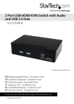
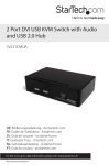
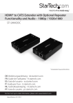
8 Port 1U Rackmount DVI USB KVM Switch
SV831DVIU
*actual product may vary from photos
DE: Bedienungsanleitung - de.startech.com
FR: Guide de l'utilisateur - fr.startech.com
ES: Guía del usuario - es.startech.com
IT: Guida per l'uso - it.startech.com
NL: Gebruiksaanwijzing - nl.startech.com
PT: Guia do usuário - pt.startech.com
For the most up-to-date information, please visit: www.startech.com
Manual Revision: 12/30/2011
FCC Compliance Statement
This equipment has been tested and found to comply with the limits for a Class B digital
device, pursuant to part 15 of the FCC Rules. These limits are designed to provide reasonable
protection against harmful interference in a residential installation. This equipment generates,
uses and can radiate radio frequency energy and, if not installed and used in accordance with
the instructions, may cause harmful interference to radio communications. However, there
is no guarantee that interference will not occur in a particular installation. If this equipment
does cause harmful interference to radio or television reception, which can be determined by
turning the equipment off and on, the user is encouraged to try to correct the interference by
one or more of the following measures:
• Reorient or relocate the receiving antenna.
• Increase the separation between the equipment and receiver.
• Connect the equipment into an outlet on a circuit different from that to which the receiver
is connected.
• Consult the dealer or an experienced radio/TV technician for help.
Use of Trademarks, Registered Trademarks, and other Protected Names and
Symbols
This manual may make reference to trademarks, registered trademarks, and other
protected names and/or symbols of third-party companies not related in any way to
StarTech.com. Where they occur these references are for illustrative purposes only and do not
represent an endorsement of a product or service by StarTech.com, or an endorsement of the
product(s) to which this manual applies by the third-party company in question. Regardless
of any direct acknowledgement elsewhere in the body of this document, StarTech.com hereby
acknowledges that all trademarks, registered trademarks, service marks, and other protected
names and/or symbols contained in this manual and related documents are the property of
their respective holders.
Instruction Manual
Table of Contents
Introduction.............................................................................................1
Packaging Contents.................................................................................................................................. 1
System Requirements............................................................................................................................... 1
Front View..................................................................................................................................................... 2
Rear View....................................................................................................................................................... 2
Installation...............................................................................................3
Hardware Installation............................................................................................................................... 3
Operation.................................................................................................5
Front Panel.................................................................................................................................................... 5
Hot-key commands................................................................................................................................... 6
Specifications...........................................................................................8
Technical Support...................................................................................9
Warranty Information.............................................................................9
Instruction Manual
i
Introduction
The SV831DVIU 8 Port 1U Rack Mount DVI USB KVM Switch allows you to control up to
8 USB connected computers with DVI or HDMI display output from a single keyboard,
mouse and monitor.
The KVM switch offers maximum control, allowing you to switch computers using hotkey commands or front panel push-buttons. Supporting resolutions up to 1920x1200
via DVI or HDMI connection (using DVI to HDMI adapter), the KVM provides the high
resolutions recommended for newer displays allowing you to take full advantage of
your screen real-estate.
A perfect addition to any server room operation, this rugged 8 port switch can be rackmounted into 1U of cabinet space.
Packaging Contents
• 1 x 1U Rack Mount KVM Switch
• 3 x Power Cord (NA/UK/EU)
• 1 x Set of rack mount brackets
• 1 x Instruction Manual
System Requirements
• DVI/HDMI enabled display device (i.e. monitor, projector, HDTV, etc)
• USB 104-key wired keyboard
• USB 3-button wired mouse
• Computer systems with an available DVI/HDMI and USB port
Instruction Manual
1
Front View
Rear View
Instruction Manual
2
Installation
Hardware Installation
WARNING: Prior to installation, please ensure that all of the computers and the KVM
switch are powered down.
Console Connection
The KVM switch is designed to use USB console connections only. A USB compatible
keyboard and mouse and DVI/HDMI* monitor must be used for the local console.
NOTE: DVI to HDMI adapters sold separately.
Plug a monitor into the Console’s DVI connector; plug a USB keyboard and a USB
mouse into the dedicated USB keyboard and mouse ports on the KVM switch. Ensure
the keyboard/mouse are connected to the proper connectors.
Instruction Manual
3
Connecting Computer to the KVM Switch
To connect a computer to the KVM switch, use the appropriate DVI/USB KVM cable (or
separate cables) to connect from one of the PC ports located on the rear panel of the
KVM switch to the USB and DVI video ports on the computer.
1. Use a male-to-male DVI video cable to connect the DVI connector on the computer’s
video card, to one of the KVM’s PC ports (i.e. PC1).
2. Use a USB type A-B Cable to connect the KVM’s USB port (type B, square connector)
for the PC port used in Step 1, and the USB port on the computer (type A, flat
connector).
3. Repeat for Steps 1 and 2 for each PC port on the KVM switch, or each computer you
wish to use on the KVM.
4. Connect the power cord from the KVM to an AC power outlet.
5. Turn the monitor on first, followed by the KVM switch via the power switch on the
rear panel.
6. Power up the first computer/device and wait for it to fully boot and test keyboard/
mouse functionality.
7. Once operation has been successfully confirmed, switch to the next port and power
up that computer/device and confirm.
Instruction Manual
4
Operation
Front Panel
Port Selection/Link LED
The LED turns green when the connected computer is powered-on. The
corresponding LED will also illuminate red when that PC port is currently selected.
Port Selection Button
Each push button on the front panel corresponds with a PC port. Pressing the
button will immediately select that port.
K/M Reset
K/M Reset resolves the majority of problems developed by keyboard and/or
mouse device replacement or configuration changes. Press down buttons 1 and 2
simultaneously for 2 seconds to reconfigure the whole system without having to
turn off the KVM switch or any attached computers.
Auto Scan
The KVM automatically scans through the powered-on computers in sequence on a
fixed time interval (see Scan Time below).
To activate Auto Scan, press down front panel push buttons “3” and “4”
simultaneously. The port LED flashes during Auto Scan. Auto Scan is effective for
powered-on computers only. To exit the Auto Scan mode, just tap any one of the
push buttons.
NOTE: When Auto Scan detects any keyboard activity, it suspends the scanning
until the activity stops; it then resumes with the next computer in sequence. The
length of the Auto Scan interval (Scan Rate) is adjustable, see below.
Instruction Manual
5
Hot-key commands
A Hot-key command is a short keyboard sequence for selecting a computer, activating
computer scan, etc. A hot-key sequence starts with two left <CTRL> keystrokes
(successively within 0.2 seconds) followed by one or two more keystrokes. A highpitch beep will be generated for each correct hot-key command; otherwise, one
low-pitch beep is generated for errors and the bad key sequence will not be forwarded
to the selected computer.
NOTE: Left <CTRL>: refers to the Control key on the left side of the keyboard.
1~8: refers to the number keys ‘1’ through ’8’ in the upper row of the keyboard. Do
not use the numeric keypad at the right of the keyboard for entering numbers for any
hot-key command.
To select a computer by hot-key command, you must know its port number, which is
determined by the KVM switch connections.
EXAMPLES:
Left <CTRL> , Left <CTRL>, 7 : Selects a computer connected to PC port 7 on the
KVM switch.
Auto Scan
In this mode, the KVM Switch automatically switches from one power-on computer
to the next, sequentially, at a fixed interval.
Left <CTRL>, Left <CTRL>, F1
When Auto Scan detects any keyboard or mouse activity, it suspends the scanning
until the activity stops. It then resumes with the next computer in sequence. The
length of the Auto Scan interval (Scan Time) is adjustable. To abort Auto Scan mode,
press the left <CTRL> key twice.
Instruction Manual
6
Manual Scan
Enables you to manually switch back and forth between the powered computers:
Left <CTRL>, left <CTRL>, F2
Press the <UP> arrow key to select the previous computer and the <DOWN> arrow key
to select the next computer. Press any other key to abort Manual Scan mode.
Scan Time
To adjust Scan Time, which sets the duration before switching to the next computer in
Auto Scan:
Left <CTRL>, Left <CTRL>, F3
The switch will beep one to four times indicating the scan interval of 3, 8, 15 and 30
seconds respectively.
Set Maximum Video Resolution
By default the KVM switch is set to output an EDID signal with a maximum video
resolution of 1024 x 768 to the host computer systems. To be able to set a higher video
resolution on the host computer systems, use the following command with the 4 digit
code for the maximum video resolution you wish to set.
NOTE: Do not use the numeric keypad for entering the 4-Digit Code. Only use the
number keys along the top row of the keyboard.
Left <CTRL>, Left <CTRL>, V, 4 digit code
4-Digit Code
Resolution
4-Digit Code
Resolution
1007
1024 x 768
1609
1600 x 900
1208
1280 x 800
1612
1600 x 1200
1210
1280 x 1024
1610
1680 x 1050
1307
1360 x 768
1910
1920 x 1080
1409
1440 x 900
1912
1920 x 1200
1410
1440 x 1050
NOTE: You may need to reboot the host computer(s) for the new settings to take affect.
If not done automatically by the host computer’s operating system, you may then
need to manually adjust the display settings to the new maximum resolution.
Instruction Manual
7
Specifications
Number of Ports
8
Computer Connectors
(per port)
1 x 29-pin DVI-I female
1 x USB type B female
1 x 29-pin DVI-I female
2 x USB type A female
1 x C14 power connector
Console Connectors
(Local)
1 x Power
8 x Port Selection/Link
LEDs
Maximum Video Resolution
1920 x 1200
Switching Method
Pushbutton, Hot-keys
Rack Mountable
Yes
On Screen Display
No
Cascadable
No
DDC Support
Yes
Audio Support
No
Enclosure Material
Metal
Power Adapter
Built-in
Operating Temperature
0°C ~ 40°C (32°F ~ 104°F)
Storage Temperature
-20°C ~ 60°C (-4°F ~ 140°F)
Humidity
0% ~ 80% RH
Dimensions
180.0mm x 438.0mm x 44.0mm
Weight
Instruction Manual
3500g
8
Technical Support
StarTech.com’s lifetime technical support is an integral part of our commitment to
provide industry-leading solutions. If you ever need help with your product, visit
www.startech.com/support and access our comprehensive selection of online tools,
documentation, and downloads.
For the latest drivers/software, please visit www.startech.com/downloads
Warranty Information
This product is backed by a three year warranty.
In addition, StarTech.com warrants its products against defects in materials
and workmanship for the periods noted, following the initial date of purchase.
During this period, the products may be returned for repair, or replacement with
equivalent products at our discretion. The warranty covers parts and labor costs only.
StarTech.com does not warrant its products from defects or damages arising from
misuse, abuse, alteration, or normal wear and tear.
Limitation of Liability
In no event shall the liability of StarTech.com Ltd. and StarTech.com USA LLP (or their
officers, directors, employees or agents) for any damages (whether direct or indirect,
special, punitive, incidental, consequential, or otherwise), loss of profits, loss of business,
or any pecuniary loss, arising out of or related to the use of the product exceed the
actual price paid for the product. Some states do not allow the exclusion or limitation
of incidental or consequential damages. If such laws apply, the limitations or exclusions
contained in this statement may not apply to you.
Instruction Manual
9
Hard-to-find made easy. At StarTech.com, that isn’t a slogan. It’s a promise.
StarTech.com is your one-stop source for every connectivity part you need. From
the latest technology to legacy products — and all the parts that bridge the old and
new — we can help you find the parts that connect your solutions.
We make it easy to locate the parts, and we quickly deliver them wherever they need
to go. Just talk to one of our tech advisors or visit our website. You’ll be connected to
the products you need in no time.
Visit www.startech.com for complete information on all StarTech.com products and
to access exclusive resources and time-saving tools.
StarTech.com is an ISO 9001 Registered manufacturer of connectivity and technology
parts. StarTech.com was founded in 1985 and has operations in the United States,
Canada, the United Kingdom and Taiwan servicing a worldwide market.