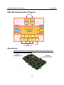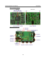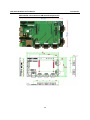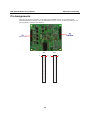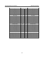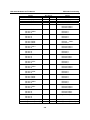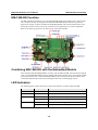
1
EM-1240 Hardware User’s Manual Fourth Edition, September 2008 www.moxa.com/product © 2008 Moxa Inc., All rights reserved. Reproduction without permission is prohibited. EM-1240 Hardware User’s Manual The software described in this manual is furnished under a license agreement and may be used only in accordance with the terms of that agreement. Copyright Notice Copyright © 2008 Moxa Inc. All rights reserved. Reproduction without permission is prohibited. Trademarks MOXA is a registered trademark of Moxa Inc. All other trademarks or registered marks in this manual belong to their respective manufacturers. Disclaimer Information in this document is subject to change without notice and does not represent a commitment on the part of Moxa. Moxa provides this document “as is,” without warranty of any kind, either expressed or implied, including, but not limited to, its particular purpose. Moxa reserves the right to make improvements and/or changes to this manual, or to the products and/or the programs described in this manual, at any time. Information provided in this manual is intended to be accurate and reliable. However, Moxa assumes no responsibility for its use, or for any infringements on the rights of third parties that may result from its use. This product might include unintentional technical or typographical errors. Changes are periodically made to the information herein to correct such errors, and these changes are incorporated into new editions of the publication. Technical Support Contact Information www.moxa.com/support Moxa Americas: Toll-free: 1-888-669-2872 Tel: +1-714-528-6777 Fax: +1-714-528-6778 Moxa China (Shanghai office): Toll-free: 800-820-5036 Tel: +86-21-5258-9955 Fax: +86-10-6872-3958 Moxa Europe: Tel: +49-89-3 70 03 99-0 Fax: +49-89-3 70 03 99-99 Moxa Asia-Pacific: Tel: +886-2-8919-1230 Fax: +886-2-8919-1231 Table of Contents Chapter 1 Introduction ..................................................................................................1-1 Overview.................................................................................................................................. 1-2 Package Checklist .................................................................................................................... 1-2 Product Features ...................................................................................................................... 1-2 EM-1240 Hardware Specifications.......................................................................................... 1-3 EM-1240 Hardware Block Diagram ........................................................................................ 1-4 Appearance .............................................................................................................................. 1-4 Dimensions .............................................................................................................................. 1-6 Chapter 2 EM-1240 Functionality .................................................................................2-1 EM-1240 Embedded Module Functions .................................................................................. 2-2 RS-232/422/485 Serial Ports.................................................................................................... 2-2 Console Port............................................................................................................................. 2-2 LAN Ports................................................................................................................................ 2-2 SD Signals ............................................................................................................................... 2-2 GPIO ........................................................................................................................................ 2-2 Pin Assignments....................................................................................................................... 2-3 Definition of SD Signals.......................................................................................................... 2-6 Mechanical Specifications of Pin Header Dimensions ............................................................ 2-6 Chapter 3 EM-1240-DK Functionality...........................................................................3-1 EM-1240-DK Function............................................................................................................ 3-2 Combining EM-1240-DK with the Embedded Module........................................................... 3-2 LED Indicators......................................................................................................................... 3-2 Wiring Requirements ............................................................................................................... 3-3 Connecting the Power .............................................................................................................. 3-3 Grounding the EM-1240 Development Kit.............................................................................. 3-3 Serial Ports and Pin Assignments............................................................................................. 3-4 Console Ports and Pin Assignments......................................................................................... 3-5 LAN Ports and Pin Assignments.............................................................................................. 3-5 SD Socket ................................................................................................................................ 3-5 GPIO ........................................................................................................................................ 3-6 Mechanical Specifications of Console and Serial Ports Pin Headers....................................... 3-6 Reset Button............................................................................................................................. 3-6 1 Chapter 1 Introduction Thank you for purchasing the Moxa EM-1240 Embedded Module. The product’s features include 4 software-selectable RS-232/422/485 serial ports, two 10/100 Mbps Ethernet ports, and SD signals for external SD socket connection based on the Moxa ARM9 32-bit 192 MHz communication processor. These features make the EM-1240 ideal for the core module of an industrial embedded system design. The EM-1240 Development Kit, which is designed for system and software program development at the system evaluation stage, is also available. The kit combines the EM-1240 and EM-1240-DK, which is the carrier board used to evaluate the EM-1240. The EM-1240’s pre-installed ready-to-run μClinux Kernel 2.6 makes it easy to develop programs for any application. In this manual, we introduce the hardware features and functions of the EM-1240 Embedded Module and the EM-1240 Development Kit. After a brief introduction of the hardware features, the manual focuses on installation and hardware configuration with device interfaces. The following topics are covered in this chapter: Overview Package Checklist Product Features EM-1240 Hardware Specifications EM-1240 Hardware Block Diagram Appearance Dimensions EM-1240 Hardware User’s Manual Introduction Overview The EM-1240 Embedded Module is designed for system integration and software development in industrial data applications. The module features 4 software-selectable RS-232/422/485 serial ports, two 10/100 Mbps Ethernet ports, and an SD function based on the Moxa ART ARM9 32-bit 192 MHz communication processor. In addition, you may order the EM-1240 Development Kit. The kit includes an EM-1240 embedded module, an EM-1240-DK carrier board, and the items needed for setting up a basic layout. The kit is makes it easy for users to evaluate the functionality of the EM-1240. You can develop and integrate specific systems on the module in advance to make the EM-1240 Embedded Module completely compatible with industrial systems and applications. The pre-installed open Linux operating system makes the EM-1240 suitable for developing the control programs used on a standard PC. The software you develop for your own applications can be stored in the onboard Flash memory. The EM-1240 lets you build an application that has a powerful serial communication capability, but which is still small in size. The EM-1240 is suited for control systems that use a distributed, embedded architecture, such as those systems used for manufacturing automation, intelligent transportation systems, medical management, and data acquisition and control. Package Checklist The EM-1240 package includes the EM-1240 embedded module only. The EM-1240 Development Kit is available for evaluation purposes. The EM-1240 Development Kit package contains the following items: y y y y y y y 1 EM-1240 Embedded Module 1 EM-1240-DK, the carrier board of the EM-1240 Development Kit Quick Installation Guide Document & Software CD Cross-over Ethernet cable Universal Power Adapter Warranty Statement NOTE: Notify your sales representative if any of the above items is missing or damaged. Product Features The EM-1240 Embedded Module has the following features: y y y y y y y y Moxa ART ARM9 32-bit 192 MHz communication processor 16 MB RAM and 8 MB Flash ROM onboard 4 software-selectable RS-232/422/485 serial ports Dual 10/100 Mbps Ethernet ports RS-232 serial console port (supports full signal and PPP) Ready-to-run μClinux Kernel 2.6.9 communication platform SD signals supported for external Secure Digital (SD) socket connection 10 GPIO reserved for system integration (to enable GPIO, SD must be disabled) 1-2 EM-1240 Hardware User’s Manual Introduction EM-1240 Hardware Specifications Model CPU RAM Flash EM-1240 Embedded Module Moxa ART ARM9 32-bit 192 MHz processor 16 MB 8 MB LAN Auto-sensing 10/100 Mbps × 2 Built-in 1.5 KV magnetic isolation Four serial ports that support RS-232/422/485 signals RS-232 signals: TxD, RxD, DTR, DSR, RTS, CTS, DCD, GND RS-422 signals: TxD+, TxD-, RxD+, RxD-, GND 4 wire RS-485 signals: TxD+, TxD-, RxD+, RxD-, GND 2 wire RS-485 signals: Data+, Data-, GND Serial Protection: 15 KV ESD for all signals Data bits: 5,6,7,8 Stop bits: 1,1.5,2 Parity: None, even, odd, space, mark Flow Control: RTC/CTS, XON/XOFF Speed: 50 bps to 921.6 Kbps, support Any Baudrate Serial Ports Serial Console Storage Expansion RS-232 × 1, full signals, supports PPP SD signals for external Secure Digital (SD) socket connection Reset Signal Power Input GPIO × 10 (to enable GPIO, SD must be disabled.) Yes Yes Buzzer signals reserved for external buzzer connection Reserve signals for the following LED connections: System: Ready × 1 LAN: 10M/Link × 2, 100M/Link × 2 Serial: TxD × 4, RxD × 4 Reserve signal for external “Reset to Default” button connection Accept external 5 VDC through pin header Dimensions (W × L) Operating Temperature Storage Temperature 90 × 80 mm -10 to 60°C (14 to 141°F), 5 to 95%RH -20 to 80°C (-4 to 176°F), 5 to 95%RH Module Interface Two 2 × 28 pin-headers; pitch: 1.27 × 1.27 (mm) GPIO Real-time Clock Watchdog Timer Buzzer Signals LED Signals 1-3 EM-1240 Hardware User’s Manual Introduction EM-1240 Hardware Block Diagram Ethernet Power Circuit RTC LAN 1 LAN 2 PHY PHY MAC MAC 16 MB SDRAM 8 MB Flash MOXA ART CPU 32-bit ARM9 192 MHz Watchdog SD/GPIO Function UART UART UART UART UART Serial Port 1 Serial Port 2 Serial Console Port 4 Port Serial Port 3 RS-232 RS-232/422/485 Appearance EM-1240 Development Kit: EM-1240 Embedded Module + EM-1240-DK, carrier board of EM-1240 Development Kit 1-4 EM-1240 Hardware User’s Manual Introduction EM-1240 Embedded Module Top View Bottom View EM-1240 Development Kit 1-5 EM-1240 Hardware User’s Manual Introduction Dimensions EM-1240 Embedded Module 1-6 EM-1240 Hardware User’s Manual Introduction EM-1240-DK, Carrier board of EM-1240 Development Kit 1-7 2 Chapter 2 EM-1240 Functionality In this chapter, we explain the basic features of the EM-1240 Embedded Module. The following topics are covered: EM-1240 Embedded Module Functions RS-232/422/485 Serial Ports Console Port LAN Ports SD Signals GPIO Pin Assignments Definition of SD Signals Mechanical Specifications of Pin Header Dimensions EM-1240 Hardware User’s Manual EM-1240 Functionality EM-1240 Embedded Module Functions The EM-1240 Embedded Module is designed to be integrated directly into the user’s system and application. The module has four software-selectable RS-232/422/485 serial ports, dual 10/100 Mbps LAN ports, 1 RS-232 console port, and GPIO/SD signals. In addition, the EM-1240 uses the Moxa ART ARM9 32-bit 192 MHz communication processor, which ensures excellent performance for data transmission. The pre-installed μClinux Kernel 2.6.9 makes it easy for users to develop programs for a variety of applications. The EM-1240 is an ideal solution for manufacturing automation, intelligent transportation monitoring, and remote device control. RS-232/422/485 Serial Ports The EM-1240 Embedded Module has 4 software-selectable RS-232/422/485 serial ports. Pin assignment diagrams are shown in a later section. The ports can be configured by software. Please refer to Software User’s Manual for details. Console Port The EM-1240 Embedded Module has 1 console port for onsite configuration. However, it can also be used as a serial port with standard RS-232 interface and PPP function support. Refer to the Software User’s Manual for details. LAN Ports The EM-1240 Embedded Module has 2 10/100 Mbps LAN ports that can be used to set up a redundant Ethernet network for non-stop operation, and the on-board transformer provides 1.5 KV isolation protection. SD Signals The EM-1240 Embedded Module provides SD signals for storage expansion. Designers can use these signals to create an SD socket. Note that you can use a Secure Digital (SD) memory card compliant with the SD 1.0 standard to provide up to 1GB of additional memory space. However, the SD signals share the same mechanical layout with GPIO. When you enable the SD signals, the GPIO function will be disabled, and vice versa. GPIO The EM-1240 Embedded Module provides 10 software-selectable GPIOs. Note that users can choose to enable either the SD Signals or the GPIO function, but not both. When you enable the GPIO function, the SD Signals will be disabled. 2-2 EM-1240 Hardware User’s Manual EM-1240 Functionality Pin Assignments There are two 56-pin pin headers on the EM-1240 embedded module. To use the EM-1240 Embedded Module to develop your own independent system, refer to the following tables for the pin assignments of jumpers JP3 and JP4. JP4 1 JP3 2 2-3 1 2 EM-1240 Hardware User’s Manual Signals Eth0_TxD_outEth0_TxD_out+ Eth0_LED_100M Eth1_RxDjnEth1_RxDjn+ Eth1_LED_100M GPIO0 (I/O) GPIO2 (I/O) GPIO4 (I/O) GPIO6 (I/O) GPIO8 (I/O) Buzzer (Beeper) LED_Ready (SW_RDY) BLCM_DO (I/O) BLCM_D2 (I/O) BLCM_D4 (I/O) BLCM_D6 (I/O) D/I (LCM) (O) E (LCM) (O) CL (LCM) (O) CS1 (LCM) (O) GND KEY_OUT0 (KEYPAD) KEY_OUT2 (KEYPAD) KEY_OUT4 (KEYPAD) KEY_I N0 (KEYPAD) KEY_I N2 (KEYPAD) GND EM-1240 Functionality JP3 Pin No. 1 2 3 4 5 6 7 8 9 10 11 12 13 14 15 16 17 18 19 20 21 22 23 24 25 26 27 28 29 30 31 32 33 34 35 36 37 38 39 40 41 42 43 44 45 46 47 48 49 50 51 52 53 54 55 56 2-4 Signals Eth0_RxDjnEth0_RxD_in+ Eth0_LED_10M Eth1_TxD_outEth1_TxD_out+ Eth1_LED_10M SW_Reset GPIO1 (I/O) GPIO3 (I/O) GPIO5 (I/O) GPIO7 (I/O) GPIO9 (I/O) HW Reset (nReset) BLCM_D1 (I/O) BLCM_D3 (I/O) BLCM_D5 (I/O) BLCM_D7 (I/O) R/W (LCM) (O) BL (LCM) (O) RST (LCM) (O) CS2 (LCM) (O) GND KEY_OUT1 (KEYPAD) KEY_OUT3 (KEYPAD) KEY_OUT5 (KEYPAD) KEY_I N1 (KEYPAD) KEY_I N3 (KEYPAD) GND EM-1240 Hardware User’s Manual Signals GND VCC (5V) VCC (5V) GND GND RS-232: RxD0 RS-422: TXD0+ RS-485: X RS-232: RTS0 RS-422: X RS-485: X RS-232: DTR0 RS-422: RXD0RS-485: Data0RS-232: RxD1 RS-422: TXD1+ RS-485: X RS-232: CTS1 RS-422: X RS-485: X RS-232: DSR1 RS-422: X RS-485: X RS-232: DCD1 RS-422: TXD1RS-485: X RS-232: RxD2 RS-422: TXD2+ RS-485: X RS-232: DCD2 RS-422: TXD2RS-485: X RS-232: DTR2 RS-422: RXD2RS-485: Data2RS-232: RxD3 RS-422: TXD3+ RS-485: X RS-232: DCD3 RS-422: TXD3RS-485: X RS-232: DSR3 RS-422: X RS-485: X RS-232: CTS3 RS-422: X RS-485: X RxD_Console (RS-232) RTS_Console (RS-232) EM-1240 Functionality JP4 Pin No. 1 2 3 4 5 6 7 8 9 10 11 12 13 14 15 16 17 18 19 20 21 22 23 24 25 26 27 28 29 30 31 32 33 34 35 36 37 38 Signals GND VCC (5V) VCC (5V) GND RS-232: TxD0 RS-422: RXD0+ RS-485: Data0+ RS-232: CTS0 RS-422: X RS-485: X RS-232: DSR0 RS-422: X RS-485: X RS-232: DCD0 RS-422: TXD0RS-485: X RS-232: TxD1 RS-422: RXD1+ RS-485: Data1+ RS-232: RTS1 RS-422: X RS-485: X RS-232: DTR1 RS-422: RXD1RS-485: Data1RS-232: RTS2 RS-422: X RS-485: X RS-232: TxD2 RS-422: RXD2+ RS-485: Data2+ RS-232: DSR2 RS-422: X RS-485: X RS-232: CTS2 RS-422: X RS-485: X RS-232: RTS3 RS-422: X RS-485: X RS-232: TxD3 RS-422: RXD3+ RS-485: Data3+ RS-232: DTR3 RS-422: RXD3RS-485: Data3TxD_Console (RS-232) 39 41 40 42 CTS_Console (RS-232) DSR_Console (RS-232) 2-5 EM-1240 Hardware User’s Manual DTR_Console (RS-232) GND Serial LED_Tx0 Serial LED_Tx1 Serial LED_Tx2 Serial LED_Tx3 GND EM-1240 Functionality 43 45 47 49 51 53 55 44 46 48 50 52 54 56 DCD_Console (RS-232) GND Serial LED_Rx0 Serial LED_Rx1 Serial LED_Rx2 Serial LED_Rx3 GND Definition of SD Signals The following table gives the definition of the SD signals. Note that the signal pins from the JP3 pin header share the same pin as the GPIO. Signal Name SD_CLK SD_CMD SD_DAT<3:0> SD_CD SD_WP Direction Output Bidirectional Bidirectional Input Input GPIO GPIO 7 GPIO 2 GPIO <6:3> GPIO 1 GPIO 0 Description Clock signal to SD/MMC Bidirectional line for command and response Bidirectional line for read and write data Card detect Write protect Mechanical Specifications of Pin Header Dimensions Refer to the following figures for the mechanical specifications of the Pin Header dimensions of the EM-1240 Embedded Module. The figures define the mechanical specifications of jumpers JP3 and JP4 on the EM-1240. 2-6 3 Chapter 3 EM-1240-DK Functionality This chapter includes information about the EM-1240-DK (carrier board of the EM-1240 Development Kit). This chapter covers the following topics: EM-1240-DK Function Combining EM-1240-DK with the Embedded Module LED Indicators Wiring Requirements Connecting the Power Grounding the EM-1240 Development Kit Serial Ports and Pin Assignments Console Ports and Pin Assignments LAN Ports and Pin Assignments SD Socket GPIO Mechanical Specifications of Console and Serial Ports Pin Headers Reset Button EM-1240 Hardware User’s Manual EM-1240-DK Functionality EM-1240-DK Function The EM-1240 Development Kit is a well-designed PCB board with complete layout. The kit helps users evaluate, develop, and integrate the EM-1240 Embedded Module into their systems and applications. Simply combine the EM-1240 Embedded Module with the Development Kit to start porting the relevant software, and create a solution for the applications you wish to implement. Refer to the following picture for the basic layout of the EM-1240-DK. Combining EM-1240-DK with the Embedded Module Insert the EM-1240 Embedded Module vertically onto the EM-1240-DK. Note that the Pin marked “JP4” on the Embedded Module must be matched with the Pin marked “JP6” on the EM-1240-DK; and the Pin marked “JP3” on the Embedded Module must be matched with the Pin marked “JP4” on the EM-1240-DK. Be careful when installing the board to avoid damaging the pins. LED Indicators The following table explains the function of the LED indicators located on EM-1240-DK. LED Name LED Color LED Function Power Green Power is on. Ready Green Power is on and system functions normally. P1-P4 (Tx) Green Serial port 1-4 is transmitting data. Off Serial port 1-4 is not transmitting data. Yellow Serial port 1-4 is receiving data. Off Serial port 1-4 is not receiving data. P1-P4 (Rx) 3-2 EM-1240 Hardware User’s Manual EM-1240-DK Functionality Wiring Requirements This section describes how to connect the EM-1240 Development Kit to serial devices. You should heed the following common safety precautions before proceeding with the installation of any electronic device: y Use separate paths to route wiring for power and devices. If power wiring and device wiring paths must cross, make sure the wires are perpendicular at the intersection point. NOTE: Do not run signal or communication wiring and power wiring in the same wire conduit. To avoid interference, wires with different signal characteristics should be routed separately. y Use the type of signal transmitted through a wire to determine which wires should be kept separate. The rule of thumb is that wiring that shares similar electrical characteristics can be bundled together. y Keep input wiring and output wiring separate. y It is advisable to label the wiring to all devices in the system. Be sure to disconnect the power cord before installing and/or wiring your EM-1240 Development Kit. ATTENTION Safety First! Be sure to disconnect the power cord before installing and/or wiring your EM-1240 Development Kit. Wiring Caution! Calculate the maximum possible current in each power wire and common wire. Observe all electrical codes dictating the maximum current allowable for each wire size. If the current goes above the maximum ratings, the wiring could overheat, causing serious damage to your equipment. Temperature Caution! Be careful when handling EM-1240 Development Kit. When plugged in, EM-1240 Development Kit’s internal components generate heat, and consequently the outer casing may feel hot to the touch. Connecting the Power You may use either a power jack or 3-pin terminal block for connecting the power. The power input range of the EM-1240-DK is from 12 to 48 VDC. Note that you may only use one power input source at the same time. DO NOT connect the power to both the power jack and terminal block simultaneously. You may use the power on-off switch to turn on and turn off the power to the Development Kit. If the power is properly supplied, the “Power” LED will light up immediately and the “Ready” LED will glow a solid green after a 25 to 30 second delay. Grounding the EM-1240 Development Kit Grounding and wire routing help limit the effects of noise due to electromagnetic interference (EMI). Run the ground wire from the ground screw to the grounding surface prior to connecting devices. 3-3 EM-1240 Hardware User’s Manual EM-1240-DK Functionality ATTENTION This product should be mounted to a well-grounded mounting surface such as a metal panel. SG V- SG: The Shielded Ground (sometimes called Protected Ground) contact is the left most contact of the 3-pin power terminal block connector when viewed from the angle shown here. Connect the SG wire to an appropriate grounded metal surface. V+ 12-48V Serial Ports and Pin Assignments The EM-1240 Development Kit has 4 software-selectable serial ports. If you would like to connect to a serial device, use male DB9 connectors. They can be configured for RS-232/422/485 by software. Refer to the Software User’s Manual for details. Furthermore, you may also use serial port pin headers to extend the serial port with other devices using a homemade cable. Simply connect one end of the cable to serial port pin header and the other end of the cable to other device. Pay attention to the cable length for the various serial communication standards. Refer to the following figure for pinouts and pin assignments of the DB9 connector and pin header. J1/J3/J4/J6 Serial Ports 1-4 1 Pin Header J1/J3/J4/J6 DCD RxD TxD DTR GND DSR RTS CTS 1 2 3 4 5 6 7 8 Male DB9 Port 1 2 3 4 5 6 7 8 9 Pin RS-232 RS-422 1 2 3 4 5 6 7 8 DCD RxD TxD DTR GND DSR RTS CTS TxDA(-) TxDB(+) RxDB(+) RxDA(-) GND ------- 3-4 4-wire RS-485 TxDA(-) TxDB(+) RxDB(+) RxDA(-) GND ------- 2-wire RS-485 ----DataB(+) DataA(-) GND ------- EM-1240 Hardware User’s Manual EM-1240-DK Functionality Console Ports and Pin Assignments The serial console port on the EM-1240-DK is an RS-232 port with full modem signal. It is designed for serial console terminals, which can be used for local configuration. PPP is also supported to make it easy to set up a modem connection for long distance data transmission. You may use the Pin header of the serial console port to extend the serial port to other devices. The pinouts of this RS-232 console port are the same as the standard serial port that was mentioned in the previous section. Male DB9 Port 1 2 3 4 5 J5 Console Port 1 6 7 8 9 LAN Ports and Pin Assignments The EM-1240 Development Kit has two 10/100 Mbps LAN ports. Connect one end of the Ethernet cable to the Development Kit LAN port and the other end of the cable to the Ethernet network. The LAN ports use 8-pin RJ45 connectors. See the following figures for the pinouts. 8-pin RJ45 1 8 1 8 Pin 1 2 3 4 5 6 7 8 Signal ETx+ ETxERx+ ----ERx----- SD Socket The EM-1240 Development Kit provides an internal SD socket for storage expansion. It allows users to plug in a Secure Digital (SD) memory card compliant with the SD 1.0 standard for up to 1 GB of additional memory space. Plug the SD card into the socket directly and remember to press the SD card first if you want to remove it. Note that the SD will not work if you enable the GPIO function. Refer to the section about the EM-1240’s SD function to see a table that describes the SD card interface. 3-5 EM-1240 Hardware User’s Manual EM-1240-DK Functionality GPIO The EM-1240 Development Kit has 10 GPIOs. You may configure digital input channels and digital output channels by software. Note that the GPIO function will not work if you enable the SD signals function. Use the GPIO pin header for connecting with devices. See the following figure for GPIO pinouts. GPIO Signal Pin Header JP7 VCC 13 11 14 12 10 VCC Mechanical Specifications of Console and Serial Ports Pin Headers Refer to the following figure for the specifications of console and serial ports of the EM-1240-DK. Reset Button Press the Reset button on the EM-1240-DK continuously for at least 5 seconds to load the factory default configuration. After the factory default configuration has been loaded, the system will reboot automatically. We recommend that you only use this function if the software is not working properly and you want to load factory default settings. To reset an embedded Linux system, always use the software reboot command />reboot to protect the integrity of data being transmitted or processed. The Reset button is not designed to hard reboot the EM-1240 Development Kit. 3-6