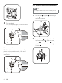
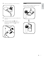
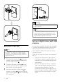
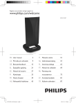
1
Register your product and get support at
www.philips.com/welcome
SDV8625T/27
EN User manual
1 Important
4
4
4
4
4
5
5
2 Your SDV8625T/27
5
6
Safety
For indoor use
For outdoor use
Notice for USA
Notice for Canada
Recycling
What’s in your box
English
Contents
3 Get started
7
Installation
7
Connect to the TV
10
Set up a digital tuner with this antenna 10
4 Frequently asked questions
11
5 Warranty and service
11
6 Glossary
12
EN
3
1 Important
Safety
•
Properly sealed against leaks at the
installation site.
•
Do not install your antenna on a wet or
windy day.
•
If the assembly starts to drop, get away
from it immediately. Remember: the
antenna, mast, cable, and metal guy wires
are all excellent conductors of electrical
current. Even the slightest touch of any
of these parts to a power line can cause
electrocution and death.
•
If any part of the antenna system should
come in contact with a power line, don’t
touch it or try to remove it yourself. Call
your local power company. They will
remove it safely.
•
If an accident occurs with the power
lines, call for qualified emergency help
immediately.
This manual contains important information
about the Philips indoor/outdoor television
antenna. Read it carefully before you start the
installation and setup.
For indoor use
•
The product shall not be exposed to
dripping or splashing and no objects filled
with liquid, such as vases, shall be placed
on the product.
•
To completely disconnect the power
input, the main plug of the product shall
be disconnected from the main AC
outlet.
•
Where the main plug is used as the
disconnect device, the disconnect device
shall remain readily operable.
•
No naked flame sources, such as lighted
candles, should be placed on the product.
For outdoor use
•
If this is the first time you install an
antenna, for your own safety as well as
others, seek professional assistance.
•
Perform as many functions as possible on
the ground.
•
Select your installation site carefully.
Remember: electric power lines and
phone lines look alike. For your safety,
assume that all overhead lines may cause
fatal injury.
•
Ensure that the installation site is
structurally capable to support all loads
(weight of the antenna, weight of ice,
weight of snow and wind force).
4
EN
Notice for USA
This equipment has been tested and found
to comply with the limits for a Class B digital
device, pursuant to part 15 of the FCC Rules.
These limits are designed to provide reasonable
protection against harmful interference in a
residential installation. This equipment generates,
uses and can radiate radio frequency energy
and, if not installed and used in accordance
with the instruction manual, may cause harmful
interference to radio communications.
However, there is no guarantee that
interference will not occur in a particular
installation. If this equipment does cause harmful
interference to radio or television reception,
which can be determined by turning the
equipment off and on, the user is encouraged
to try to correct the interference by one or
more of the following measures:
•
Relocate the receiving antenna.
•
Increase the separation between
equipment and receiver.
Connect the equipment into an outlet on
a circuit different from that to which the
receiver is connected.
•
Consult the dealer or an experienced
radio/TV technician for help.
All other devices shall bear the following
statement in a conspicuous location on the
device:
This device complies with part 15 of the FCC
Rules. Operation is subject to the following
two conditions: (1) This device may not cause
harmful interference, and (2) this device must
accept any interference received, including
interference that may cause undesired
operation.
The packaging of this product is intended to
be recycled. Contact your local authorities for
information about how to recycle the packaging.
When this logo is attached to a product, it
means a financial contribution has been paid to
the associated national recovery and recycling
system.
© 2011 Koninklijke Philips Electronics N.V. All
rights reserved. Reproduction in whole or in
part is prohibited without the written consent
of the copyright owner. Trademarks are the
property of Koninklijke Philips Electronics N.V.
or their respective owners.
Notice for Canada
Class B Clause
This digital apparatus does not exceed the Class
B limits for radio noise emissions from digital
apparatus as set out in the Radio Interference
Regulations of the Canadian Department of
Communications.
2 Your
SDV8625T/27
This Class B digital apparatus complies with
Canadian ICES-003.
Congratulations on your purchase and welcome
to Philips!
Recycling
To fully benefit from the support that Philips
offers, register your product at www.philips.
com/welcome.
Your product is designed and manufactured
with high quality materials and components,
which can be recycled and reused.
Never dispose of your product with other
household waste. Please inform yourself about
the local rules on the separate collection of
electrical and electronic products. The correct
disposal of your old product helps prevent
potentially negative consequences on the
environment and human health.
EN
5
English
•
What’s in your box
1
3
2
1x
1x
5
6
2x
9 10
2x
1x
1x
7
8
1x
4x
4x
12
11
1x
4
13
4x
1x
14
1x
a SDV8625T/27 antenna
h 25mm wood screws
b Power supply 100-240V AC / 6V DC
500mA
i 6m coax cable with connectors
j Weather boot
c Wall/Mast bracket
k Power injector
d Nut
l Plastic anchors
e U-Bolts
m Washer
f Mast clamps
n 40mm Hexagon screw
g Nuts with lock washers
6
EN
Installation
Installation information
This antenna uses a power inserter module to
power the antenna amplifier.
It is essential for proper operation of this
antenna system that the power inserter
be connected between the antenna and
any devices such as splitters, matching
transformers, networks, etc.
Determine the signal strength
Before Installation, determine the best
location for optimum reception. It is important
for the antenna to have an unobstructed path
to the transmitter. For best results, ensure the
antenna faces the location of the transmitter.
Note
•• Indoor, choose a location near a window
which gives the antenna a clear view of the
transmitter.
Note
•• Place the antenna away from metal surface to
avoid interference.
a
For indoor wall mount installation
Note
•• Complete all assembly work on the ground
b
before installing on a wall or an antenna mast.
1
c
Use the nut , washer , and hexagon
screw to attach the antenna to the
wall/mast bracket.
d
a
b
c
d
Antenna with built-in amplifier
Power inserter module
Splitters or matching
transformers (not included)
TV or video device
2
Use the screw holes of the wall/mast
bracket as a guide to mark position for
the wood screws.
EN
7
English
3 Get started
For outdoor mast mount installation
Note
•• Complete all assembly work on the ground.
Raise the completed antenna after assembly.
1
3
Use the nut , washer , and hexagon
screw to attach the antenna to the
wall/mast bracket.
For wood wall
Use the wood screws to fix the antenna
to the wood wall firmly.
3.2mm
(1/8”)
27±5mm
1.1”±0.2”
For concrete wall
Drill four holes on concrete wall, put four
plastic anchors into the holes. Use wood
screws to fix the antenna to the concrete
wall firmly.
7.9mm
(5/16”)
35±5mm
1.4”±0.2”
8
EN
2
Insert U-bolts into the holes of the
wall/mast bracket . Slide the mast
clamps onto the U-bolts . Attach
the four nuts with lock washers to the
U-bolts .
3
Attach the assembly to the mast firmly.
Rotate
4
5
English
You can make a 90 degree rotation to the
antenna or the mounting post.
Rotate the mast in its mount to adjust the
direction.
Attach the coaxial cable to the F
connector on the underside of the unit.
Position the weather boot over the
connection.
EN
9
Warning
•• The power injector and power supply are for
indoor use only.
Tip
•• This antenna includes a 19.7ft roll of 3C-2V
coaxial cable. If this is not adequate for your
needs, replace the cable with a RG-6 coaxial
cable instead of adding an extension.
Set up a digital tuner with this
antenna
Connect to the TV
Note
•• As previously noted, the amplifier (Power
injector + Power supply) must be placed inline between the antenna and any splitter or
additional devices.
1
2
3
10
Connect the coaxial cable from the
antenna to the connector labeled ANT
on the power injector .
Connect the power injector to the
antenna input on the TV, digital set-top
box, splitter or other devices.
Connect the power supply plug to
the power injector , and then plug the
power supply adaptor into a 100-240V
AC receptacle.
EN
You can install available channels with the digital
TV tuner. This automatic process is part of the
setup of the tuner. Ensure the antenna has
set up properly before the tuner can receive
viewable channels.
There are two ways to connect the antenna to
the TV:
•
Connect the antenna to a digital tuner.
If the signal strength is good enough, the
channels can be memorized in the tuner
automatically .
•
Connect the antenna directly to the TV.
Tune to the analogue channels and find
the best antenna location. Then reconnect the antenna to the digital tuner.
Ensure the signal strength is good enough
before you install the channels with the
tuner.
5 Warranty and
service
Can this antenna work with Analogue
transmissions?
Yes, this antenna can receive analogue
television broadcasts in the UHF and VHF
bandwidths.
Warranty information can be found at: www.
philips.com/welcome
Can this antenna receive digital or work with
ATSC broadcasts?
Yes, this antenna is designed to receive ATSC
and HDTV broadcasts in the UHF & VHF
bandwidths.
Can the antenna be powered by a DC power
supply in a boat, RV or camper?
Yes, there is a DC power socket located at the
back of the antenna. Plug your cable/adapter
into the antenna and then into your power
source.
Where should I place the antenna in order to
get the best reception possible?
Choose a location near a window which gives
the antenna a clear view of the transmitter.
Tip
•• For best reception, place the antenna away
from metal surface to avoid interference.
Can I set up this antenna with a digital tuner?
Yes, this antenna can be set up with a digital
tuner (see the section on “Set up a digital
tuner with this antenna”).
English
4 Frequently
asked questions
For technical support, send us an email
with the model number of the product
and a detailed description of your problem
to:[email protected]
Limited One-Year Warranty Philips warrants
that this product shall be free from defects
in material, workmanship and assembly,
under normal use, in accordance with the
specifications and warnings, for one year from
the date of your purchase of this product. This
warranty extends only to the original purchaser
of the product, and is not transferable. To
exercise your rights under this warranty, you
must provide proof of purchase in the form of
an original sales receipt that shows the product
name and the date of purchase. For customer
support or to obtain warranty service, please
call 1-919-573-7854. THERE ARE NO OTHER
EXPRESS OR IMPLIED WARRANTIES. The
liability of Philips is limited to repair or, at
its sole option, replacement of the product.
Incidental, special and consequential damages
are disclaimed where permitted by law. This
warranty gives you specific legal rights. You may
also have other rights that vary from state to
state. Warranty information can also be found
at: www.philips.com/welcome
EN
11
6 Glossary
F
A
FM (Frequency Modulation)
In radio broadcasting: a method of modulation
in which the frequency of the carrier voltage
is varied with the frequency of the modulation
voltage.
Amplifier
A device, either a single stage or a large scale
circuit with multiple stages for creating gain,
i.e. it makes small signals larger.
Antenna
A device, such as a rod or wire, which picks up
a received radio frequency signal or radiates a
transmitted RF signal.
ATSC (Advanced Television Systems
Committee)
The Advanced Television Systems Committee,
Inc., is an international, non-profit organization
developing voluntary standards for digital
television. The high definition television
standards defined by the ATSC produce wide
screen 16:9 images up to 1920x1080 pixels
in size -- more than six times the display
resolution of the earlier standard. However,
many different image sizes are also supported,
so that up to six standard-definition “virtual
channels” can be broadcast on a single 6 MHz
TV channel.
C
Coaxial
A single copper conductor, surrounded with
a layer of insulation, covered by a surrounding
copper shield and finally, an insulating jacket.
An unbalanced transmission line with constant
impedance. In audio, this type is commonly
used for low level, line signals terminated in
RCA connectors.
12
EN
H
HDTV (High-Definition Television)
It is a digital television broadcasting system
with higher resolution than traditional
television systems (standard-definition TV,
or SDTV). HDTV is digitally broadcast;
the earliest implementations used analog
broadcasting, but today digital television
(DTV) signals are used, requiring less
bandwidth due to digital video compression.
U
UHF (Ultra high frequency)
In radio or TV broadcasting: it is the frequency
range of electromagnetic waves which lies
between 300 MHz and 3 GHz (3000 MHz).
V
VHF (Very high frequency)
In radio or TV broadcasting: it is the frequency
range of electromagnetic waves which lies
between 30 MHz and 300 MHz.
© 2011 Koninklijke Philips Electronics N.V.
All rights reserved.
DFU_SDV8625T_27_V1.1