1
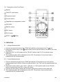
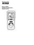
DVM345DI DIGITAL MULTIMETER DIGITALE MULTIMETER MULTIMETRE NUMERIQUE DIGITALES MULTIMETER User Manual Gebruikershandleiding Manuel d’utilisation Gebrauchsanleitung DVM345DI -- DIGITAL MULTIMETER 1. INTRODUCTION Thank you for buying the DVM345DI. This device enables the user to measure AC and DC voltages, AC and DC currents, resistance, capacitance and temperature. The device can be interfaced with a computer and the user can also test diodes, transistors and audible continuity. 2. SAFETY The meter has been designed according to IEC-1010 concerning the safety requirements for electronic measuring instruments with an overvoltage category (CAT II) and pollution 2. Respect the following safety instructions to ensure maximum personal safety and to keep the device itself in good working order : • Protect yourself against electroshocks. • Do not use this device for any other application than those described in this manual. • Full compliance with safety standards can only be guaranteed if the device is used with the supplied test leads. If necessary, they should be replaced with identical leads or leads with identical electric ratings. All test leads should be in good working order. 2.1. Use • Never exceed the specified limit values for the various measurement ranges. • Do not touch unused terminals when the meter is connected to a circuit. • Place the range selector switch in the highest position if the value to be measured is unknown beforehand. • Disconnect all test leads from the circuit to be tested prior to selecting a different function. • When performing measurements on TV’s or switching power circuits, the user should keep in mind that voltage surges may occur at test points. These surges may damage the meter. • Never perform resistance measurements on live circuits. • Exercise extreme caution when working with voltages in excess of 60VDC or 30Vrms AC. Keep your fingers behind the probe barriers while using the device. 2.2. Symbols Important information with reference to safety, consult the manual ! Dangerous voltage may be present Earth ground Double insulation (Protection class II) DVM345DI 1 GB 2.3. Maintenance • Always disconnect the test leads from all current sources before opening the meter. • Replace blown fuses with an identical one or a fuse with identical voltage and current ratings (15A/250V). • Do not use the device and have it checked by qualified personnel if anomalies are observed or in case of malfunction. • Use a damp cloth and a mild detergent to clean the device. Never apply abrasives or solvents to the meter. 3. DESCRIPTION This device is a professional auto-ranging measuring instrument. All measured values are displayed on a 3 ¾ digit LCD. The device is equipped with a 38-segment bar graph and can be used to measure DC & AC voltages (both auto-ranging), DC & AC current, temperature, resistance (auto-ranging) and capacitance. The user can also test diodes, transistors and audible continuity. 3.1. "ON/OFF"-push button Used to turn the device ON or OFF. The beeper sounds when this button is pushed. 3.2. DC/AC-RU -button 8VHGWRVHOHFW'&RU$&YROWDJHUDQJH'&RU$&FXUUHQWUDQJH RU sounds when this button is pushed. range. The beeper 3.3. "R-H" button Press this button to switch to manual operation when the device is in the auto-ranging mode. "R-H" will be displayed. Hold the button for more than one second to return to the auto-ranging mode. Push this button to change the voltage ranges as follows : 4V → 40V → 400V → 1000V. 3XVKWKLVEXWWRQWRFKDQJHWKHUHVLVWDQFHUDQJHVDVIROORZV0 →0 →N →N →N → 3.4. "B/L"-button Press this button to turn the back light ON or OFF. 3.5. Input Jacks This meter has 4 input jacks with overload protection. Connect the black test lead to the "COM"jack and the red test lead to the following input jacks : Function Red Lead Connection Input Limit VDC/VAC 9 9 9 mA 10A 1000VDC or 750Vrms AC 250VDC or 250Vrms AC 250VDC or 250Vrms AC 400mA DC or rms AC 10A DC or rms AC mA 10A DVM345DI 2 GB 3.6. Description of the Front Panel Display "ON/OFF" push button Transistor socket Function switch Capacitance or temperature socket Input jacks RS232C socket "B/L"-button "R-H" button DC/AC- or -button 4. OPERATION 4.1. Voltage Measurements 1. Connect the black test lead to the "COM"-MDFNDQGWKHUHGWHVWOHDGWRWKH9 -jack. 2. Place the function switch in the -position and connect the test leads to the source you wish to measure. 3. Select the VDC- or VAC-mode with the "DC/AC"-button (push "R-H" for manual range selection). 4. The measured value will be displayed on the LCD. The polarity of the red test lead is indicated with DC measurements. 4.2. Current Measurements 1. Connect the black test lead to the "COM"-jack and the red test lead to the "mA"-jack for measurements up to 400mA. Switch the red test lead to the "10A"-jack for measurements up to 10A. 2. Place the function switch in the "4mA"-, "400mA"- or "10A"-position and use the "DC/AC"button to select either the DCA- or the ACA-mode. 3. Connect the test leads in series with the load in which the current is to be measured. 4. The measured value will be displayed on the LCD. The polarity of the red test lead is indicated with DC measurements. DVM345DI 3 GB 4.3. Resistance Measurements 1. Connect the black test lead to the "COM"-jack and the red test lead to the "V/ -jack. The polarity of the red test lead is positive (+). 2. 3ODFHWKHIXQFWLRQVZLWFKLQWKH -range to be used and connect the test leads to the resistance you wish to measure. NOTE : v The device may need a few seconds to produce a stable reading when measuring UHVLVWDQFHVLQH[FHVVRI0 7KLVLVHQWLUHO\QRUPDO v The message "OL" and the full bar graph will be displayed if the input is not connected, e.g. with an open circuit. v Disconnect the circuit to be tested and make sure that all capacitors have been fully discharged before measuring the in-circuit resistance. 4.4. Capacitance Measurements 1. Place the function switch in the "nF"-position. 2. Make sure that the capacitor has been fully discharged prior to connecting the capacitor to the capacitance socket. WARNING : Disconnect all test leads from the circuit to be tested before inserting the capacitor in the capacitance socket. Make sure that no components are connected to this socket when performing voltage measurements with test leads. 4.5. Temperature Measurements 1. Place the function switch in the "TEMP"-position. 2. Connect the "K"-type thermocouple with the temperature socket on the front panel and contact the object in question with the thermocouple. WARNING : Remove the thermocouple before selecting a different function in order to avoid electroshocks. Do not connect the thermocouple to the "TEMP"-socket unless all test leads have been disconnected from the circuits you wish to test. 4.6. Audible Continuity Test 1. Connect the black test lead to the "COM"-jack and the red test lead to the 9 -jack. The polarity of the red test lead is positive (+). 2. Place the function switch in the " "-position and push the " "-button on the front panel. 3. Connect the test leads with two points of the circuit you wish to test. The built-in buzzer will sound if continuity exists (for resistances < 30 DVM345DI 4 GB 4.7. Diode Test 1. Connect the black test lead to the "COM"-MDFNDQGWKHUHGWHVWOHDGWRWKH9 -jack. The polarity of the red test lead is positive (+). 2. Place the function switch in the " "-position. 3. Connect the red test lead to the anode and the black test lead to the cathode of the diode to be tested. 4. The forward voltage drop of the diode will be displayed on the LCD. 4.8. Transistor Test 1. Place the function switch in the "hFE"-position. 2. Determine whether the transistor is NPN or PNP and locate the emitter, base and collector leads. Insert the leads into the proper holes of the hFE-socket on the front panel. 3. The display will show the approximate hFE-value at the moment of testing. Base current 10µA, Vce 3.0V. WARNING : Disconnect all test leads from the circuit to be tested before connecting the transistor with the hFE-socket. Make sure that no components are connected to the hFE-socket when performing voltage measurements with test leads. 4.9. Interfacing the Meter with a PC 1. Run the RS232C-cable from the computer's serial ports to the meter. 2. Press "ON/OFF" to activate the meter and turn on the computer. WARNING : 1. Only use a RS232C serial interface cable. Do not attempt to modify the length of this cable. 2. Please read the information on the supplied disk. 5. SPECIFICATIONS Max. accuracy is achieved during a one-year period after calibration. Ideal circumstances require a temperature of 18 to 28°C (64 to 82°F) and a max. relative humidity of 75%. 5.1. General Specifications Max. Voltage between Terminals and Earth Ground Power Supply Ranging Method Display Overrange Indication Polarity Indication : : : : : : Battery-Low Indication Operating Temperature : The " "-symbol is displayed : 5 to 35°C (41 to 95°F) DVM345DI 1000VDC or 750 Vrms AC (sine wave) 9V-battery (NEDA1604 or 6F22) Auto/Manual 3 ¾ digit LCD, 38-segment bar graph "OL" appears on display "-" is displayed automatically 5 GB Storage Temperature Dimensions Weight : -10 to 60°C (14 to 140°F) : 78 x 186 x 35mm : 300g (including battery) 5.2. DC Voltage Range Resolution 4V 1mV 40V 10mV 400V 0.1V 1000V 1V Input impedance : 10MΩ. Accuracy ±0.5% of rdg ± 3 digits ±0.8% of rdg ± 3 digits 5.3. AC Voltage Range Resolution Accuracy 4V 1mV ±1.2% of rdg ± 5 digits 40V 10mV 400V 0.1V 750V 1V ±1.5% of rdg ± 5 digits Input impedance : 10MΩ Response : average response, calibration in rms of a sine wave. Frequency range : 40Hz – 400Hz. 5.4. Resistance Range Resolution Accuracy 400 0.1 4k 1 ±1.2% of rdg ± 3 digits 40k 10 400k 0.1k 4M 1k 40M 10k ±3.0% of rdg ± 5 digits Max. open-circuit voltage : 3.0V. Overload protection : 250VDC or 250Vrms AC for all ranges. 5.5. DC Current Range Resolution Accuracy 4mA 1µA ±1.2% of rdg ± 3 digits 400mA 0.1mA ±1.2% of rdg ± 3 digits 10A 10mA ±2.0% of rdg ± 8 digits Overload protection : 15A/250V-fuse for the 10A-range. 5.6. AC Current Range Resolution Accuracy 4mA 1µA ±1.5% of rdg ± 8 digits 400mA 0.1mA ±1.5% of rdg ± 8 digits 10A 10mA ±3.0% of rdg ± 8 digits Overload protection : 15A/250V-fuse for the 10A-range. DVM345DI 6 GB Frequency range Response : 40 to 400Hz : average response, calibration in rms of a sine wave. 5.7. Capacitance Range 4nF 400nF Resolution 1pF 0.1nF Accuracy ±4.0% of rdg ± 5 digits ±4.0% of rdg ± 5 digits Resolution 1°C 1°C Accuracy ±3.0% of rdg ± 3 digits ±3.0% of rdg ± 5 digits 5.8. Temperature Range 0 to 400°C 401 to 750°C 5.9. Audible Continuity Function Description Built-in buzzer sounds if continuity exists (< 30Ω) 5.10. Diode Function Resolution 1mV Test Current 25µA Open-Circuit Voltage 3.0V Range 1 to 1000 Base Current 10µA Vce 3.0V 5.11. Transistor Function hFE 6. ACCESSORIES - User manual Set of test leads 9V-battery (NEDA1604 or 6F22) "K"-type thermocouple Holster RS232C-cable 1 disk of 1.44MB DVM345DI 7 GB