1
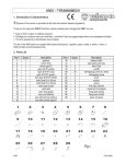
KNS8 – MECHANICAL SKELETON
1. Introduction & Characteristics
Thank you for buying the KNS8 ! Read this manual carefully before bringing the KNS8 into use.
• Build a gearbox and learn how automatic transmissions and motors work.
• Easy to build, no glue or soldering required.
• Dislodge the pre-cut pieces when you need them and not before. Sand the jagged edges before use (sandpaper
included)
• The kit is powered by 2 AA-batteries (not included).
The kits of the KNS-series are supplied with prepunched boards, a gearbox, gears, shafts, a switch, a motor, a
battery holder and all necessary parts.
Note that the figures with the assembly instructions can be found in the second folder “KNS8 – Figures”!!!
2. Parts List (see also KNS8 – Figures)
Part n°
1
2
3
4
5
6
7
8
9
10
11
12
13
14
15
16
17
Quant.
1
1
1
1
1
1
1
1
1
1
1
1
1
2
2
2
2
Description
gearbox
motor 3Vdc
battery holder
slide switch with wire
metal shaft (2 x 40mm)
metal shaft (3 x 52mm)
pinion gear 8T
face gear 36T/10T (white)
gear 40T/0T (white)
gear 40T/10T (red)
gear 40T/10T (green)
wire with terminal (yellow)
wire with terminal (green)
metal foot (U-shaped)
nylon connector (N-shaped)
nylon pad (5.6 x 4.8 x 1.95)
nylon post (H : 6mm)
Part n°
18
19
20
21
22
23
24
25
26
27
28
29
30
31
32
33
Quant.
6
18
18
4
2
2
2
8
15
3
10
5
4
1
2
6
Description
nylon nut M3
nut M2
screw (2 x 8mm)
self-tapping screw (2 x 4mm)
screw (3 x 14mm)
screw (3 x 18mm)
screw (3 x 22m)
washer (3.2 x 10.0 x 0.5mm)
washer (2.6 x 6.0 x 0.5mm)
PVC tube (15mm)
nylon pad (Ø 8mm)
fixing plate (L-shaped)
nylon post (H : 3mm)
spring (L : 50mm)
spring (L : 20mm)
self-tapping screw (2 x 6mm)
3. Prepunched Boards (see “KNS8 – Figures”)
4. Assembly (see also “KNS8 – Figures”)
Fig. 3 : The gears (n°9/10/11/8) should be placed to the left of the pinion gear. One N-shaped nylon connector
(n°15) should point downward and the other one upward. Insert the motor as depicted in the drawing. Note
that the protruding edge should point towards the metal case.
Fig. 4 : Identify boards 2 & 3. The screw opening in board 3 is located in the middle, while the one in board 2 lies
off to the left. Make sure board 1 is not upside-down.
KNS8
1
VELLEMAN
Fig. 5
Fig. 7
Fig. 8
Fig. 9
Fig. 10
Fig. 12
Fig. 13
Fig. 14
: Screw the gearbox to the upside of board 11. Consult the figure for the position of the opening.
: Screw the battery holder to board 11.
:* = left, ** = right.
: Don’t screw the arms down too tightly. A somewhat looser fit enables your mechanical skeleton to move
more smoothly.
: Don’t screw the legs down too tightly. A somewhat looser fit enables your mechanical skeleton to move
more smoothly.
: The U-shaped metal foot should be flush with the ground. Note : * = left, ** = right.
: Fix the spring (piece n° 32) to the right side of the head under the angle depicted in the figure.
: Attach boards 21 & 22 to board n° 1. Mount board 23 next.
5. Troubleshooting (see also “KNS8 – Figures”)
• Make sure the wiring is correct
• Adjust the screws on the legs and arms if the KNS8 doesn’t move even though the motor is running.
• Bend the U-shaped metal feet slightly (see figure 16) to make the KNS8 move more smoothly.
Note : The specifications and contents of this manual can be subject to change without prior notice.
KNS8 – MECHANISCH SKELET
1. Inleiding & Kenmerken
Dank u voor uw aankoop ! Lees deze handleiding aandachtig voor u de KNS8 in gebruik neemt.
• Bouw een tandwielkast en leer hoe een automatische overbrenging en een motor werken.
• Maak de voorgesneden vormen pas los wanneer u ze nodig hebt. Schuur de scherpe randjes af voor gebruik
(schuurpapier meegeleverd)
• De kit wordt aangedreven door 2 AA-batterijen (niet inbegrepen).
De kits van de KNS-reeks worden geleverd met voorgesneden vormen, tandwielkast, koppeling, stangen,
schakelaar, motor, batterijhouder en alle vereiste onderdelen.
U vindt de figuren met de montagetips in de tweede folder : “KNS8 – Figuren”!!!
2. Lijst van onderdelen
Nr.
1
2
3
4
5
6
7
8
9
10
KNS8
Hoev.
1
1
1
1
1
1
1
1
1
1
Beschrijving
tandwielkast
motor 3Vdc
batterijhouder
schuifschakelaar met draad
metalen as (2 x 40mm)
metalen as (3 x 52mm)
rondsel 8T
tandwiel 36T/10T (wit)
tandwiel 40T/0T (wit)
tandwiel 40T/10T (rood)
Nr.
18
19
20
21
22
23
24
25
26
27
2
Hoev.
6
18
18
4
2
2
2
8
15
3
Beschrijving
nylon moer M3
moer M2
schroef (2 x 8mm)
zelftappende schroef (2 x 4mm)
schroef (3 x 14mm)
schroef (3 x 18mm)
schroef (3 x 22m)
borgring (3.2 x 10.0 x 0.5mm)
borgring (2.6 x 6.0 x 0.5mm)
PVC buis (15mm)
VELLEMAN
11
12
13
14
15
16
17
1
1
1
2
2
2
2
tandwiel 40T/10T (groen)
draad met connector (geel)
draad met connector (groen)
metalen voet (“U”-vormig)
nylon connector (“N”-vormig)
nylon kraagring (5.6 x 4.8 x 1.95)
nylon ring (H : 6mm)
28
29
30
31
32
33
10
5
4
1
2
6
nylon pad (Ø 8mm)
bevestigingsplaat (“L”-vormig)
nylon kraagring (H : 3mm)
veer (L : 50mm)
veer (L : 20mm)
zelftappende schroef (2 x 6mm)
3. Onderdelen (zie “KNS8 – Figuren”)
4. Montage (zie ook “KNS8 – Figuren”)
Fig. 3 : Plaats de tandwielen (n°9/10/11/8) links van het rondsel. Richt de ene N-vormige nylon connector (n°15)
naar beneden en de andere naar boven. Breng de motor aan volgens de tekening. Merk op dat de
uitstekende rand naar de metalen behuizing moet worden gericht.
Fig. 4 : Zoek platen 2 & 3 uit. De schroefopening in plaat 3 is centraal geplaatst. De schroefopening in plaat 2
bevindt zich aan de linkerkant. Houd plaat 1 niet ondersteboven!.
Fig. 5 : Schroef de tandwielkast vast aan de voorkant van plaat 11. Bekijk de figuur om te weten waar de
schroefopening zich bevindt.
Fig. 7 : Vijs de batterijhouder vast aan plaat 11.
Fig. 8 :* = links, ** = rechts.
Fig. 9 : Schroef de armen niet te hard vast zodat ze soepel kunnen bewegen.
Fig. 10 : Schroef de benen niet te hard vast zodat ze soepel kunnen bewegen.
Fig. 12 : De “U”-vormige metalen voet moet evenwijdig zijn geplaatst met de grond. Opmerking : * = links, ** =
rechts.
Fig. 13 : Bevestig het veertje (onderdeel nr. 32) aan de juiste kant van het hoofd en onder dezelfde hoek (zie figuur).
Fig. 14 : Maak platen 21 & 22 vast aan plaat 1 en monteer vervolgens plaat 23.
5. Problemen en oplossingen (zie ook “KNS8 – Figuren”)
• Controleer of de bedrading juist is
• Maak de schroeven van de armen en benen wat losser indien de KNS8 niet beweegt hoewel de motor loopt.
• Plooi de U-vormige voeten heel lichtjes (zie figuur 16) om de KNS8 vlotter te doen bewegen.
Opmerking : De specificaties en de inhoud van deze handleiding kunnen worden gewijzigd zonder
voorafgaande kennisgeving.
KNS8
3
VELLEMAN
KNS8 – SQUELETTE MECANIQUE
1. Introduction et Caractéristiques
Nous vous remercions de votre achat ! Lisez la notice présente attentivement avant la mise en service du KNS8.
• Assemblez une boîte d’engrenages et familiarisez-vous avec l’opération de transmissions et de moteurs.
• Ne détachez les pièces précoupées qu’au moment où vous en avez besoin. Polissez les arêtes avant d’employer
la pièce en question (papier d’émeri inclus)
• Le kit est piloté par 2 piles AA (non incluses).
Les kits de la série KNS sont livrés avec : éléments précoupés en bois, pignonnerie, tiges, interrupteur, moteur,
porte-piles et toutes les pièces nécessaires.
Vous trouverez les figures avec les instructions de montage dans la deuxième partie, c.-à-d. : “KNS8 – Figures”!!!
2. Liste des pièces
Pièce
1
2
3
4
5
6
7
8
Quant.
1
1
1
1
1
1
1
1
Description
boîte d’engrenages
moteur 3Vcc
porte-piles
glissière avec fil
axe métallique (2 x 40mm)
axe métallique (3 x 52mm)
satellite 8T
pignon 36T/10T (blanc)
Pièce
18
19
20
21
22
23
24
25
Quant.
6
18
18
4
2
2
2
8
9
1
pignon 40T/0T (blanc)
26
15
10
11
12
13
14
15
16
17
1
1
1
1
2
2
2
2
pignon 40T/10T (rouge)
pignon 40T/10T (vert)
fil avec connecteur (jaune)
fil avec connecteur (vert)
pied métallique en “U”
connecteur en nylon en "N"
canon en nylon (5.6 x 4.8 x 1.95)
embout en nylon (H : 6mm)
27
28
29
30
31
32
33
3
10
5
4
1
2
6
Description
écrou en nylon M3
écrou M2
vis (2 x 8mm)
vis taraudeuse (2 x 4mm)
vis (3 x 14mm)
vis (3 x 18mm)
vis (3 x 22m)
rondelle de serrage (3.2 x 10.0 x
0.5mm)
rondelle de serrage (2.6 x 6.0 x
0.5mm)
tube PVC (15mm)
canon en nylon (Ø 8mm)
panneau de fixation en "L"
embout en nylon (H : 3mm)
ressort (L : 50mm)
ressort (L : 20mm)
vis taraudeuse (2 x 6mm)
3. Pièces précoupées (voir “KNS8 – Figures”)
4. Montage (voir “KNS8 – Figures”)
Fig. 3 : Positionnez les pignons (n°9/10/11/8) à gauche du satellite. Le premier connecteur ”N” en nylon (n°15) est
dirigé vers le sol et l’autre vers le ciel. Installez le moteur selon la figure. Remarquez que la protubérance
doit indiquer le boîtier métallique.
KNS8
4
VELLEMAN
Fig. 4 : Cherchez les panneaux 2 & 3. L’ouverture de montage de panneau n°3 se trouve au milieu, tandis que
celle de panneau n°2 se trouve à gauche. Veillez à ce que panneau n°1 ne soit pas sens dessus dessous.
Fig. 5 : Vissez la boîte d’engrenages sur le devant de panneau n°11. Regardez la figure pour localiser l’ouverture
de montage.
Fig. 7 : Vissez le porte-piles sur panneau n°11.
Fig. 8 :* = gauche, ** = droite.
Fig. 9 : Evitez de trop serrer les vis des bras comme ceci diminue la souplesse des mouvements.
Fig. 10 : Evitez de trop serrer les vis des jambes ceci diminue la souplesse des mouvements.
Fig. 12 : Le pied en “U” doit être parallèle au sol. Remarque : * = gauche, ** = droite.
Fig. 13 : Fixez le ressort (pièce n°32) à l’endroit et sous l’angle appropriés (voir figure).
Fig. 14 : Fixez les panneaux 21 & 22 au panneau n°1 et montez ensuite panneau n°23.
5. Problèmes et solutions (voir également “KNS8 – Figures”)
• Vérifiez si le câblage est correct
• Desserrez les vis des jambes et des bras si le KNS8 ne bouge pas malgré que le moteur soit allumé.
• Pliez les pieds en U légèrement afin d’assouplir les mouvements du KNS8 (voir figure 16).
Remarque : Les spécifications et le contenu de cette notice peuvent être modifiées sans notification
préalable.
KNS8 – MECHANISCHES SKELETT
1. Einführung und Eigenschaften
Wir bedanken uns für den Kauf des KNS8 ! Lesen Sie diese Bedienungsanleitung vor Inbetriebnahme sorgfältig
durch.
• Bauen Sie ein Getriebe und machen Sie sich mit dem Funktionieren einer automatischen Transmission und eines
Motors vertraut.
• Entfernen Sie die vorgeschnittenen Formen erst dann wenn Sie sie brauchen. Schmirgeln Sie die scharfen
Kanten vor Gebrauch (Schleifpapier mitgeliefert).
• Der Bausatz arbeitet mit 2 AA-Batterien (nicht mitgeliefert).
Die Bausätze der KNS-Serie werden mit vorgeschnittenen Formen, einem Getriebe, Zahnrädern, Achsen, einem
Schalter, einem Motor, einem Batteriehalter und allen erforderlichen Teilen geliefert.
Beachten Sie, dass die Figuren sich zusammen mit den Montageanweisungen im zweiten Teil befinden : “KNS8 –
Abbildungen”!!!
KNS8
5
VELLEMAN
2. Stückliste
Nr.
1
2
3
4
5
6
7
8
9
10
11
12
13
14
15
16
17
Anzahl
1
1
1
1
1
1
1
1
1
1
1
1
1
2
2
2
2
Beschreibung
Getriebe
Motor 3Vdc
Batteriehalter
Schiebeschalter mit Draht
Metallachse (2 x 40mm)
Metallachse (3 x 52mm)
Ritzel 8T
Zahnrad 36T/10T (weiß)
Zahnrad 40T/0T (weiß)
Zahnrad 40T/10T (rot)
Zahnrad 40T/10T (grün)
Draht mit Anschluss (gelb)
Draht mit Anschluss (grün)
Metallfuß (“U”-förmig)
Nylonanschluss (“N”-förmig)
Nylonbuchse (5.6 x 4.8 x 1.95)
Nylonring (H : 6mm)
Nr.
18
19
20
21
22
23
24
25
26
27
28
29
30
31
32
33
Anzahl
6
18
18
4
2
2
2
8
15
3
10
5
4
1
2
6
Beschreibung
Nylonmutter M3
Mutter M2
Schraube (2 x 8mm)
Schneidschraube (2 x 4mm)
Schraube (3 x 14mm)
Schraube f (3 x 18mm)
Schraube (3 x 22m)
Unterlegscheibe (3.2 x 10.0 x 0.5mm)
Unterlegscheibe (2.6 x 6.0 x 0.5mm)
PVC-Rohr (15mm)
Nylonbuchse (Ø 8mm)
Befestigungsplatte (“L”-förmig)
Nylonring (H : 3mm)
Feder (L : 50mm)
Feder (L : 20mm)
Schneidschraube (2 x 6mm)
3. Teile (siehe “KNS8 – Abbildungen”)
4. Zusammenbau (siehe auch “KNS8 – Abbildungen”)
Fig. 3 : Stellen Sie die Zahnräder (n°9/10/11/8) links vom Ritzel. Richten Sie den einen N-förmigen Nylonanschluss
(n°15) nach unten und den anderen nach oben. Montieren Sie den Motor gemäß Abbildung. Beachten Sie,
dass der herausragende Rand auf das Metallgehäuse gerichtet sein muss.
Fig. 4 : Suchen Sie Platte 2 & 3 aus. Die Schraubenöffnung in Platte 3 befindet sich in der Mitte. Die
Schraubenöffnung in Platte 2 befindet sich an der linken Seite. Halten Sie Platte 1 nicht falsch herum!
Fig. 5 : Schrauben Sie das Getriebe an der Vorderseite von Platte 11 fest. Ziehen Sie die Abbildung zu Rate um zu
wissen wo sich die Schraubenöffnung befindet.
Fig. 7 : Schrauben Sie den Batteriehalter an Platte 11 fest.
Fig. 8 :* = links, ** = rechts.
Fig. 9 : Schrauben Sie die Arme nicht zu fest an so dass sie geschmeidig bewegen können.
Fig. 10 : Schrauben Sie die Beine nicht zu fest an so dass sie geschmeidig bewegen können.
Fig. 12 : Der “U”-förmige Metallfuß soll parallel zum Boden verlaufen. Bemerkung : * = links, ** = rechts.
Fig. 13 : Befestigen Sie die Feder (Teil Nr. 32) an der richtigen Seite des Haupts und unter demselben Winkel
(siehe Abbildung).
Fig. 14 : Befestigen Sie Platte 21 & 22 an Platte 1 und montieren Sie dann Platte 23.
5. Fehlersuche (siehe auch “KNS8 – Abbildungen”)
• Kontrollieren Sie ob die Verdrahtung richtig ist
• Lockern Sie die Schrauben der Beine und Arme etwas wenn das KNS8 nicht bewegt obwohl der Motor läuft.
• Verbiegen Sie die U-förmigen Füße ein bisschen (siehe Abbildung 16) damit das KNS8 geschmeidiger laufen
kann..
Bemerkung : Änderungen in Technik und Ausstattung vorbehalten.
KNS8
6
VELLEMAN
KNS8 – ESQUELETO MECÁNICO
1. Introducción y Características
¡Gracias por haber comprado el KNS8! Lea cuidadosamente las instrucciones del manual antes de montarlo.
•
•
Monte una caja de engranajes y familiarícese con el funcionamiento de transmisiones y motores.
Sólo separe las piezas previamente cortadas si las necesita. Lije los bordes dentados antes de usar la pieza
(papel de lija incluido)
• El kit funciona con 2 pilas AA (no incluidas).
Los kits de la serie KNS se entregan con : piezas de madera previamente cortadas, una caja de engranajes,
piñones, ejes, un conmutador, un motor, portapilas y todas las piezas necesarias.
¡Encuentre las figuras con las instrucciones de montaje en la segunda parte, es decir : “KNS8 – Figuras”!
2. Lista de piezas
Pieza
1
2
3
4
5
6
7
8
9
10
11
12
13
14
15
16
17
Cantidad
1
1
1
1
1
1
1
1
1
1
1
1
1
2
2
2
2
Descripción
Pieza
caja de engranajes
18
motor 3Vcc
19
portapilas
20
conmutador deslizante con hilo
21
eje metálico (2 x 40mm)
22
eje metálico (3 x 52mm)
23
satélite 8T
24
piñón 36T/10T (blanco)
25
piñón 40T/0T (blanco)
26
piñón 40T/10T (rojo)
27
piñón 40T/10T (verde)
28
hilo con conector (amarillo)
29
hilo con conector (verde)
30
base metálica en forma de “U”
31
conector de nylon en forma de "N"
32
cañón de nylon (5.6 x 4.8 x 1.95)
33
anillo de nylon (H : 6mm)
Cantidad
6
18
18
4
2
2
2
8
15
3
10
5
4
1
2
6
Descripción
tuerca de nylon M3
tuerca M2
tornillo (2 x 8mm)
tornillo autoroscante (2 x 4mm)
tornillo (3 x 14mm)
tornillo (3 x 18mm)
tornillo (3 x 22m)
arandela de ajuste (3.2 x 10.0 x 0.5mm)
arandela de ajuste (2.6 x 6.0 x 0.5mm)
tubo de PVC (15mm)
cañón de nylon (Ø 8mm)
panel de fijación en forma de “L”
anillo de nylon (H : 3mm)
resorte (L : 50mm)
resorte (L : 20mm)
tornillo autoroscante (2 x 6mm)
3. Piezas previamente cortadas (véase “KNS8 – Figuras”)
4. Montaje (véase también “KNS8 – Figuras”)
Fig. 3 : Coloque los piñones (n°9/10/11/8) a la izquierda del satélite. Apunte el primer conector ”N” de nylon (n°15)
hacia el suelo y el otro hacia el cielo. Instale el motor según la figura. Preste atención a que el saliente
apunte hacia la caja metálica.
Fig. 4 : Busque los paneles 2 & 3. La abertura de montaje del panel n°3 se encuentra en el medio. La abertura de
montaje del panel °2 se encuentra a la izquierda. Asegúrese de que el panel n°1 no se vuelva al revés.
KNS8
7
VELLEMAN
Fig. 5 : Atornille la caja de engranajes a la parte frontal del panel n°11. Consulte la figura para localizar la apertura
de montaje.
Fig. 7 : Atornille el portapilas al panel n°11
Fig. 8 : * = izquierda, ** = derecha.
Fig. 9 : No apriete los tornillos de los brazos demasiado porque esto disminuye la flexibilidad de los movimientos.
Fig. 10 : No apriete los tornillos de las patas demasiado porque este disminuye la flexibilidad de los movimientos.
Fig. 12 : La base en forma de “U” debe estar paralela al sol. Observación : * = izquierda, ** = derecha.
Fig. 13 : Fije el resorte (pieza n°32) al buen lado de la cabeza y bajo el ángulo apropiado (véase figura).
Fig. 14 : Fije los paneles 21 & 22 al panel n°1 y luego monte el panel n°23.
5. Solución a problemas (véase también “KNS8 – Figuras”)
• Asegúrese de que el cableado sea correcto
• Desatornille los tornillos de las patas y los brazos si el esqueleto no se mueve a pesar de que el motor está activado.
• Pliegue la base en forma de “U” ligeramente a fin de permitir al KNS8 moverse más suavemente (véase figura 16).
Observación : Se pueden modificar las especificaciones y el contenido de este manual sin previo aviso.
KNS8
8
VELLEMAN