1
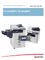
B/W-MULTIFUNCTIONAL SYSTEM FOR PAPERSIZE UP TO A3
FS-6025MFP/ FS-6030MFP
M d l name: TPM-6030MFP
Module
TPM 6030MFP
KYOCERA ACADEMY
Author:
U. Kunter
Creation:
03/11
Version:
1.0
Note:
All the contents of this document have been carefully researched. However, we cannot assume
liability for the information provided being accurate, complete and up to date.
Note for students
This training manual contains information, topics for discussion, exercises
concerning your course, and is organized into individual “lessons”. The aim of
organizing it in this way is to gain practical knowledge by following specific,
carefully structured (learning) steps as presented in our Learning Units (LU ).
In order to make the training material simpler and clearer, we have marked the
most important learning points with symbols.
This symbol indicates Learning Objectives.
Learning objectives help you keep your focus on the subject matter and enable
you to check your success at the end of the training.
This symbol indicates Exercises.
These exercises give you the opportunity to apply your knowledge hands-on.
This symbol
y
indicates a KyoQuizZ.
y Q
Quizzes enable students to test their knowledge by answering review
questions.
This symbol indicates a Summary.
The contents of the preceding chapter are presented in an overview.
We hope this manual is a valuable tool for you to find your own personal way
of learning.
We wish you success and hope you enjoy reading, studying and “using” this
documentation!
Your KYOCERA ACADE MY
LE 01 Overview
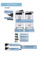
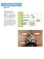
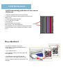
At a look
DF-470
500 Sheet Finisher
AK-470 Bridge unit
FS-6030MFP
FS-6025MFP
FS-6020/
FS
6020/ B (without Document Processor)
PF-470
500 sheet x 1 cassette
paper feeder + cabinet
PF-471
500 sheet x 2 Cassette
paper feeder
FAX System (U)
IB-50
IB
50
Gigabit Ethernet
USB Keyboard
Card Reader Holder
UG-33
Thin Print Activation kit
These Options will be activated
by the registration on the
Kyocera Mita Homepage
Card Authentication
Kit(B)
LE 01 Overview
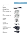
Options in detail
DP
Original size: A5 –A3
Paper weight:
Simplex: 45 – 160 g/m²
Duplex: 50 – 120 g/m²
max. 50 sheet (50 – 80 g/m²)
g/m )
PF-470
1 x 500 sheet magazine (80 g/m²)
60-163 g/m², A3, A4, A5, Ledger, Legal,
Folio, Oficio II, Letter
DF-471
2 x 500 sheet magazine (80g/m²)
60-163 g/m², A3, A4, A5, Ledger, Legal,
Folio, Oficio II, Letter
CB-470
CB
470 wooden
CB-472 metal
Cabinet base
CB-471 wooden
CB 473 metal
CB-473
t l
Socket for height increase
Only in combination with
PF-470/ PF-471
DF-470
500 sheet Finisher
With stapler for different staple positions
52-256 g/m², A3, A4, A5, customized (98
x 148 bis 297 x 432 mm),
Staple capacity max. 50 Blatt A4
(25 Blatt A3)
AK-470
Bridge Unit
necessary for DF-470
LE 01 Overview
Options in detail
Fax System (U)
ITU-T Super G3
Modem: max. 33,6 Kbit/s
Data transferrate max. 3 Sekunden (with JBIG)
Scan resolution: normal, fine, superfine, ultrafine
Operating sytem:
Networkfax: Windows 2000/XP/Vista/7/Server 2003/Server
2008
Original size: up to A3
Compressions approach:
JBIG, MMR, MR, MH
Fax properties: Fax, Networkfax, Duplex-receipt/-sending,
encrypted receipt/-sending, fax polling.
USB Card Reader
In combination with Card Authentication Kit
Also usable memory:
MDDR2-256/512/1024
Other options:
PCL Barcode Flash Modul 3.0 (Typ B/C)
KYOmulticode 1.0 (B/C)
Interfaces:
1 x Gb Lan, 1 x USB Printport, 2 x USB Host,
2 x eKUIO Port (1 = IB-50; 2 = Fax System-U)
1 x CF-Card (behind the lower eKUIO cover)
1
2
LE 01 Overviewt
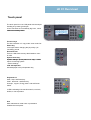
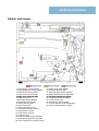
Touch panel
The touch panel is a new LCD panel with the simple
handling in Kyocera typical style.
A lot of functions are controlled by big icons, which
makes the handling easier
easier.
Function keys
For direct selection of:• copy mode• scan mode• fax
Status key
current job status• changing the job priority• job
cancelling• journal
Document box•
Fax box• USB-Stick memory administration• scanto-USB
System menu key•
System settings• reports (also menu map)• counter
report• accounting system
• service settings
LED Job Separator
Indicates paper in the job separator tray
Keyboard with
Start-, Stop- and Reset key.
Clear-, Quick No.- and Enter key.
Interrupt-, Logout-, Energy saver- and soft Power
switch.
3 LED’s indicating if the machine send’s, receive’s,
buffers, or has a problem.
Hint
With maintenance
i t
mode
d U201 it’
it’s possible
ibl tto
initialize the touch panel.
LE 02 Installation
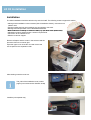
Installation
The initial installation should be carried out by technical staff. The following reasons support this advice:
• Although initial installation is documented ("Quick Installation Guide"), instructions are
seldom read.
• Transport safety devices are sometimes not recognized or removed.
• Damage from transportation can be identified beforehand.
• Brief introduction according to customer needs (e
(e.g.
g tips about toner replacement).
replacement)
• Adjustment of basic settings as per customer requirements.
• Connection to the network or PC.
• Effective customer support.
Remove all tape‘s and the carton in the exit area and the
protective foil on the scanner glas.
Open the upper cover of the DP
DP-470
470 and remove the
secure pad from the separation roller.
After shaking insert the toner box.
box
The yield of the installation toner is 3000
pages (in accordance with ISO/IEC 19798)
Install the job separator tray.
LE 02 Installation
I t ll ti (continuation)
Installation
The scanner locking is needed for the transport of the
machine.
If you didn’t unlock, the display shows call service (C3100). In
this case, switch off the machine unlock the lever and switch
on the machine.
By every transport you have to use this securing device
device.
In maintenance mode U002 the scanner move’s to the
transport position and you can lock the scanner.
The lever is also protected. For transport securing push the
small hook and then insert the lever.
After switching on the machine the developers fill up mode start’s
automatically for round about 5 minutes.
In this time you can make the most important machine settings
via the install wizard.
After setting the language you can set date and time, also the
network settings and the settings for the optional fax system.
After installing the DF-470 it‘s not possible to insert
Memory
y card‘s.
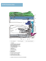
LE 03 Construction
1. Cassette
2. Cassette paper feed section
3 MP tray paper feed section
3.
4. Conveying section
5. Transfer/Separation section
6. Charger roller unit
7. Drum unit
8. Developer unit
9. Toner container
10. Fuser unit
11. Eject section
12. Duplex/conveyning section
13. Image scanner unit (ISU)
14. Laser scanner unit (LSU)
15. Document processor (DP) * 3
*3 : Model with Document Processor as standard
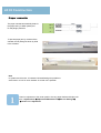
LE 03 Construction
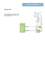
Paper
p feeder
By inserting the cassette the liftmotor (LM) starts.
It stops by swichting the LIFTFULL sensor.
The automatic paper size detection is controlled by
sensor PWSW (width) and PLSW1 – 3 (length).
Paper cassette level
The paper level in the cassette is detected by 2
sensor‘s on the rear of the machine.
(PAPEMP1 and 2)
Note
For easier replacement of the paper feed unit, the
LIFTFULL sensor is installed in the bottom plate of
the frame.
LE 03 Construction
Paper cassette
The paper cassette automatically detect’s
the paper size by PWSW (width) and
PLSW (lenght) switches.
To prevent paper jam by overload of the
cassette, the lift plate goes down by slide
in the cassette.
Note
In Systemmenu/Counter Æ Cassette-/Universalsettings it‘s possible to
select metric or inch for each cassette. So mixed use is possible.
U034 for adjustment of the center position of every paper feeder and duplex unit
also in Systemmenu Æ Adjustment/Maintenance Æ Service Settings Æ
Æ Center Line Adjustment
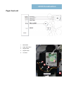
LE 03 Construction
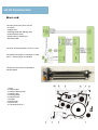
Paper
p feed unit
1.
Main Motor
2.
Paper feed clutch
3.
Regist clutch
4.
Duplex clutch
5
5.
Lift motor
5
LE 03 Construction
Paper
p feed unit
The registration roller has a big diameter to prevent paper
curl.
Feed from the cassette’s
The Paper feed drive is started approximately 25ms prior to the secondary feed for registration of the
leading edge of the paper.
Paper loop
NAME
Cassette feed clutch
Regist sensor
Regist clutch
Cassette
feed
Regist & feed
roller feed
LE 03 Construction
Duplex unit
The Job Separator is used to turn around the
paper for duplex printing
printing. Therefore it’s
it s better
when the tray is empty.
LE 03 Construction
D
Drum
unit
it
The main parts of the drum unit are:
• a-Si drum
• Charge roller
• Cleaning
g blade and cleaning
g roller
• LED-bracket to erase
• Sweep roller for waste toner
• DK Relay PWB
The drum surface p
potential is 270V ((+/-20V))
The waste toner bottle is controlled by a LED
(WTL) - Sensor (WTS) combination.
The life time of the drum is specified to
300.000 pages.
1. Drum
2. Charger roller
3. Charger cleaning roller
4. Charger case
5. Cleaning
g blade
6. Cleaning roller
7. Scraper
8. Sweep roller
9. Drum frame
10. Cleaning lamp (CL)
LE 03 Construction
Developing unit
Mono component system
300.000 pages
DC Voltage Vdc 160 V
AC Voltage Vpp 1.80 kV
No Toner sensor available. As soon as the Main motor moves, toner is
transported from the toner catridge into the
developer unit
1. Developing roller
2. Developing screw A
3. Developing screw B
4. Developing blade
5. Magnet blade
6. Developer case
7. Upper developer cover
8. Toner container
LE 03 Construction
Transfer and Separation
The transfer of the toner from the
drum to the paper happens by the
transfer unit.
The separation is done by separation
needles and a bias voltage, as also
by the drum separator which pick up
the paper mechanically from the
drum.
Contact springs for transfer- and
separation voltage..
voltage
LE 03 Construction
Fuser unit
The Fuser unit is only available as one
unit.
The most important specifications are:
1 contact Thermostat on the edge of the
heat roller.
2 Thermistor’s for controlling overheat .
2 Fuser heater
Drive start timing: 135°C
Ready : 150°C
Print:165
Print:165°
The disassembling of the fuser unit is
complicated.
A reset in Maintenance Mode isn’t necessary after C6XXX error code.
Reset is possible by power off/on the system.
LE 03 Construction
Eject unit
The Eject unit has 2 trays.
The main tray is the inner tray.
The secondary tray is the Job
Separator.
Th
These
ttrays are controlled
t ll d b
by EPS
sensor (Eject_Full_Upper) and PFS
sensor (Eject_Full_Lower), also by
JEPS (Job eject papersensor).
The capacity of the Job Separator is
normally 50 sheets 80g/m², but it is
possible to store more then 100 sheets
sheets.
Because the system uses the upper
eject path for re-feeding the paper for
Duplex printing this might give a
problem.
LE 03 Construction
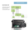
Laser Scanner Unit
Despite the speed of more than 39600
rpm the LSU is quiet, because the
polygon mirror is only 30mm.
The motor of the polygon mirror stops
immediately at the end of printing.
LE 03 Construction
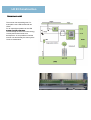
Scanner unit
The scanner has something new. For
example the new LED bracket with 28
LED‘s.
For an equal light spread over the LED
bracket is a light guide plate.
The advantage of LED is the lower energy
consumption and the lower heat
development. So it‘s possible to seal the
scanner unit and thereby the scan system
is free of maintenance.
LE 03 Construction
Scanner unit
The Image Scanner Unit is fixed with 4
screws. After replacing the unit the number on
the lens must align with the scale.
After replacing the LED bracket or ISU it‘s necessary
to make a scanner calibration with test chart
7505000005.
LE 03 Construction
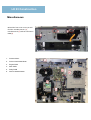
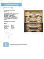
Miscellaneous
Behind the front inner cover you will find the Humidity Sensor (1), Interlockswitch (2) and DK connection
PWB (3)
1.
Scanner Motor
2.
Drive unit with Main Motor
3.
Engine PWB
4.
Main PWB
5.
Relay PWB
6.
Switch cassette heater
LE 03 Construction
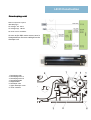
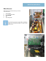
Miscellaneous
Below the Inner Tray and the fan duct you will find
more components.
1.
2.
3
3.
4.
5.
LVU sub PWB
AC cut PWB (Relay PWB)
LVU main PWB
LSU
High voltage PWB
Since February 2011 the LVU main PWB is modified so
that the AC cut PWB (Relay PWB) is not longer needed.
needed
(SB-2K3-004)
LE 03 Construction
PWB s
PWB’s
1. Main PWB (MPWB)
2. Engine PWB (EPWB)
3. High Voltage PWB (HVPWB)
4. Power source PWB (PSPWB)
5. Power source PWB – sub (PSBWB-S)
6. Operation panel PWB main (OPPWB-M)
7. Operation panel PWB left (OPPWB-L)
8. Operation panel PWB right (OPPWB-R)
9. LCD-PWB (LCDPWB)
10. LCD relay PWB (LCDRPWB)
11. CCD PWB (CCDPWB)
12. APC PWB (APCPWB)
13. BD PWB (BDPWB)
14. DRUM PWB (DRPWB)
15. Drum relay PWB (DRRPWB)
16. Developing PWB (DEVPWB)
17 Developing relay PWB (DEVRPWB)
17.
18. Relay PWB (RYPWB)
19. RFID PWB (RFPWB)
LE 03 Construction
Switch and sensor
1. Home position sensor (HPS)
2. Original detection switch (ODSW)
3. Original size sensor (OSS)
4. Front cover switch (FCSW)
5. Right cover switch (RCSW)
6. Feed sensor (FS)
7. MP paper sensor (MPPS)
8. Registration sensor (RS)
9. Duplex sensor (DUS)
10. Eject sensor (ES)
11. Paper full sensor (PFS)
12. Job paper full sensor (JPFS)
13. Paper sensor 1 (PS1)
14 P
14.
Paper sensor 2 (PS2)
15. Lift sensor (LS)
16. Paper size width switch (PWSW)
17. Paper size length switch (PLSW)
18. Toner container lock sensor (TCLS)
19. Main power switch (MSW)
20. Interlock switch (ILSW)
21. Cassette heater switch (CHSW)
22. Bridge detection switch (BRDSW)
23. Job eject papersensor (JEPS)
24. Temperature sensor (TEMS)
25. Toner sensor (TS)
26. Waste toner sensor (WTS)
27. Fuser thermistor (FTH) temperature.
28. Toner container switch (TCSW)
LE 04 Maintenance
Maintenance Kits
For maintenance there is no tool kit
necessary.
After assembling the units you have to reset
the maintenance call. Therefore select
Service Menu Æ Adjustment/
Maintenance Æ Service Adjustment.
The scanner is free of maintenance, so you
only have to clean the contact glas and the
slit glass.
Maintenance interval: 300.000 pages
MK-475
Drum Unit
DK-475
Developer Unit
DV-475
Fuser Unit
FK-475(E)
Transer Unit
TR-475
Primary feed unit
MPF roller
MPF separation pad
Regist cleaner
MK-470
For the document processor
Feed system
Separation roller
Retard guide
In the product video you will find a perfect guide for the
maintenance kit replacement.
LE 04 Maintenance
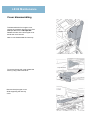
Cover disassembling
Most of the cover parts are fixed without
screws. It’s important to look at the hook
points and to know the proper sequence
for disassembling.
We start with the Rear cover.
Firstly remove the DP-connector.
Then remove 6 screws (see picture at
the right) and pull the rear cover upwards
and release 3 hooks.
And now to the Left lower cover.
Firstly remove the upper cassette and
open the front cover.
Remove 2 screws.
Release 3 hooks (A).
Pull the left cover upwards and release 9
hooks (B).
Remove the cover.
LE 04 Maintenance
Cover disassembling
To disassemble the front upper cover,
remove the cassette, open the front cover
and
d open allll covers on the
th right
i ht side.
id
Release 2 hooks of the front upper cover
and tilt the cover forward.
Now we can disassemble the inner tray.
To remove the tray left cover release the
hook by using a flat screwdriver.
Remove the eject upper cover
while supporting the rear tray
cover.
LE 04 Maintenance
Cover disassembling
Remove the inner rear tray cover by pulling it out on the left
side first.
Remove one screw and the connector.
And then remove the power source fan duct.
LE 04 Maintenance
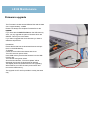
Firmware upgrade
The Firmware includes several different files and the data
size is approximately 105MB.
Please use always the complete Firmware file for the
upgrade
upgrade.
If you store also the SKIP File Data on the USB memory
stick, you only upgrade the parts of firmware which are
different. This may be much faster.
If you want to upgrade the whole firmware you have to
delete the skip file first.
Preparation:
Extract the file that has the download firmware and put
them on the USB Memory.
To Update:
Check the current firmware release with U019.
Turn OFF the main power switch.
Insert USB memory that has the firmware into the USB
memory slot.
Turn ON the main p
power switch.
About 50 seconds later, “Firmware Update” will be
displayed (this shows the download has started).
The display shows the software that is now upgrading.
When finished, turn OFF the main power switch and
remove the USB memory.
The upgrade via CF card is possible in exactly the same
way.
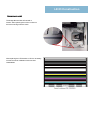
LE 04 Maintenance
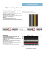
U 425 automatically calibration of the scanner
U-425,
After repairing or replacement of the CCD unit, scanner,
New calibration chart 7505000005
scanner-LED bracket or control PWB.
LAB value with Barcode on the test chart.
• calibration chart (P/N: 7505000005).
The calibration start with input of the LAB values. These
LAB values are notified on the chart.
chart
After entering the values it’s absolutely necessary to do the
calibration with the supplied chart.
Attention:
• The calibration chart is light-sensitive
• Never use the calibration chart with the document feeder
Adjust Original
For the geometrical adjustment, the position of the
calibration chart must be accurate.
Therefore you have to correct the current measurements of
the calibration chart:
• Main: Enter the value of the distance from the leading
edge to the black belt („DIST1).
• Sub Lead: Enter the value of the distance from the left
edge to the black belt (DIST2).
• Sub Tail: Enter the value of the distance (DIST3).
LE 04 Maintenance
U-425,, automatically
y calibration of the scanner
(Follow up)
1. Place the calibration chart on the contact glass.
2. Close the document processor carefully so that the chart
doesn’t move.
3. Activate the maintenance mode.
4. U-411 and select „01 Table“ .
5. Quit with OK.
The scanner starts its processes.
Leading edge
After 1 minute „OK“ should displayed.
If the calibration is not successful the display shows „NG“.
Control the position of the calibration chart and try it once
more.
G
Gray
adjustment
dj t
t
The half-tone calibration is only in the
System Menu Æ Adjustment/Maintenance Æ
Æ Gray adjustment
1. Print calibration chart 1
2. Put calibration chart on the contact glass and
start measuring.
3. Put calibration chart 2 (it came with the
machine) on the contact glass and push start.
After the calibration switch the machine OFF and
ON again.
LE 04 Maintenance
System settings
Activity
Entry in the service settings (Adjustment/Maintenance).
Recommendation
• If the copier or print quality is bad.
• If you need a detail report of the technical settings (for technician).
• For settings of the fax connectivity.
• For special settings (by moving location or replacing units).
Tip
• Detailed information in the operation guide (^ÇàìëíãÉåíLj~áåíÉå~åÅÉ).
• Some settings are only available for the administrator.
• Default User and Password is the print speed followed up with 2 zero
2500
2500 FS-6025MFP
3000
3000 FS-6030MFP
2500 / 3000
2500 / 3000
Density Adjustment
Copy
Set‘s the brightness of the copy in 7 steps.
Possible value: -3 (light), -2, -1, 0 (normal), 1, 2, 3 (dark)
Send/Box
Adjust scan density when sending or storing the data in Document Box in 7 steps.
Possible value: -3 (light), -2, -1, 0 (normal), 1, 2, 3 (dark)
Background density
Copy (Auto)
Darkens or lightens overall background density adjustment during copying. Adjustment in 7 steps
Possible value: -3 (light), -2, -1, 0 (normal), 1, 2, 3 (dark)
Send/Box (Autom.)
Darkens or lightens overall background density when sending images or storing them in the
Document Box. Adjustment in 7 steps
Possible value: -3 (light), -2, -1, 0 (normal), 1, 2, 3 (dark)
Toner Save Level (EcoPrint)
Copy
py / Print
Darkens or lightens overall EcoPrint appearance during copying or printing. Adjustment in 5 levels.
Value: 1 to 5
Print Density
Adjust print density. Adjustment in 5 levels.
Value: 1 to 5
LE 04 Maintenance
System menu
Auto Color Correction
This setting allows you to adjust the detection level used by the machine to determine whether
the original is color or black and white during Auto Color Mode. Setting a lower value will result
in more originals being identified as color, while a larger value will tend to increase the number
of originals being identified as black and white.
Value: 5 (B & W), 4, 3, 2, 1 (Color)
Correcting Black Line
Correct fine black lines (black streaks), which may appear on the copies, when the document
processor is used.
Value:
Off: No correction
On (Low): Correction performed. The reproduction of the image becomes lower when using OFF.
On (High):Correction performed. Select this item if the black streak remains after using On (Low).
The reproduction of the image becomes lower when using On (Low).
Display
p y Brightness
g
Set the brightness of the touch panel.
Value: 1 (Darker), 2, 3, 4 (Lighter)
Gray Adjustment
(see page 8)
Drum Refresh 1
Use this mode when images are blurred or smeared. This takes about 90 seconds. Press [Start] to
perform Drum Refresh.
Drum Refresh 2
U thi
Use
this mode
d when
h white
hit spots
t appear on iimages. T
Takes
k about
b t 90 seconds.
d
To use [Drum Refresh 2], load Ledger or A3 size paper into the multi purpose tray. Press [Start]
to perform Drum Refresh.
When you run [Drum Refresh 2], the machine makes a vibrating sound for about 90 seconds
until drum refreshing is completed. The toner soiling on the ejected paper is normal and does
not indicate a fault.
Auto Drum Refresh Auto Drum Refresh may be executed when the machine is turned on or has recovered
from the low power mode or sleep mode. Auto Drum Refresh is executed automatically to keep
tthe
e best image
age qua
quality
ty by monitoring
o to g its
ts pe
peripheral
p e a te
temperature
pe atu e a
and
d humidity.
u d ty
Short:
maximum 180 seconds
Normal:
maximum 360 seconds
Long:
maximum 450 seconds
When an error state such as condensation is detected, [Normal] and [Long] may take a maximum of 630
seconds
DP Adjustment.
Adjust scan action of the document processor. Place the adjustment original in the document processor.
Service Adjustment:
• Switched off units can be activated
• Reset of maintenance counter
• Adjustment of Center Position of cassettes
MPF and Duplex
• Start of the developer mode.
Maintenance
Enable Repaired Unit
LE 04 Maintenance
Maintenance mode
Activity
Enter the maintenance mode.
Recommendation
• For setting the U-Parameter
• To print special reports (Eventlog)
• To print test charts for adjustments
• To adjust and calibrate the machine
Requirement
• Knowledge of how to use the maintenance mode.
• Knowledge about the functions of the U-Parameter.
Tip
The maintenance mode is not for user!
Starting the maintenance mode:
Variant 1:
Variant 2:
In copy mode Æ 1087 1087
Button Status/Print cancel Æ 1087 1087
Take variant 2 if variant 1 doesn’t work.
For example if the accounting is active.
I special
In
i l cases lik
like C-code
C
d you have
h
tto open and
d close
l
th
the ffrontt cover after
ft
entering 10871087.
Navigation in maintenance mode:
Entries:
Confirm:
Return:
numeric keys or < > key
START- or OK-key
Return- or Stop- key
Quit the maintenance mode:
With the numeric keys by 001 and confirm with START key
LE 04 Maintenance
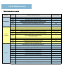
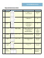
Maintenance mode
Section
Item No.
Content of maintenance item
Default setting*
General
U000
Outputting an own-status report
-
U001
Quit the maintenance mode
-
U002
S i the
Setting
h ffactory d
default
f l d
data
-
U004
Setting the machine number
-
U019
Displaying the ROM version
-
U021
Memory initializing
-
U030
Checking the operation of the motors
-
U031
Checking switches and sensors for paper conveying
-
U032
Checking the operation of the clutches
U033
Checking the operation of the solenoids
Initialization
Drive
Paper feed
Conveying
system
U034
U035
U037
U051
U053
Optical
Adjusting the print start timing, Leading edge registration,
Center line
Setting
g the p
printing
g area for folio p
paper
p
Checking the operation of the fan motors
LSU out top -18/ -15/ -21
LSU out left 6/ 8/ 3/ 3/ -4
330/ 210
All/ Eject/ Low Power
Adjusting the deflection in the paper
Setting the adjustment of the motor speed ( main motor, main
motor MPT, main motor duplex, Polygon motor, Eject motor)
0/ 0/ 0/ 0
-2/ -2/ -7/ 0/ 0
U063
Adjusting the shading position
0
U065
Adjusting the scanner magnification
0/-14
U066
Adjusting the scanner leading edge registration
22/0
U067
Adjusting the scanner center line
24/ 0
U068
Adjusting the scanning position for originals from the DP
0/ 0
U070
Adjusting the DP magnification
0/0
U071
Adjusting the DP scanning timing
0/0/0/0
U072
Adjusting the DP center line
0/0/0
U089
Outputting a MIP-PG pattern
-
U099
Adjusting original size detection
0/0.0/0
40/30/20/19
0/0.0/0
LE 04 Maintenance
Maintenance mode
Section
Item No.
Content of maintenance item
Default setting*
High voltage
U100
Setting the main high voltage
-
U101
Setting the voltage for the primary transfer
0/0/0/0190 650/900/1100/
450/650/750
U108
Setting separation shift bias
4
U111
Checking the drum drive time
-
U118
Displaying the drum history
-
U127
Checking/clearing the transfer count
-
U140
Displaying
p y g developer
p bias
170/2700/60
U147
Setting for toner applying operation
0 (OFF)
U150
Checking sensors for toner
-
U157
Checking the developer drive time
-
U161
Setting the fuser control temperature
135/150/165
U199
Displaying fuser heater temperature
-
U201
Initializing the touch panel
-
U203
Checking DP operation
-
U207
Checking the operation panel keys
-
U222
Setting the IC card type
Other/ SSFC
U243
Checking the operation of the DP motors
-
U244
Checking the DP switches
-
U250
Checking/clearing the maintenance cycle
150000
U251
Checking/clearing the maintenance counter
-
U252
Country settings
Europa/Metric
U253
Zählimpulse für Kopienzähler bei A3 Format
Double count
U260
Selecting the timing for copy counting
After ejection
U285
Setting service status page
ON
Developer
Fuser
Operation panel
and support
equipment
Mode setting
LE 04 Maintenance
Maintenance mode
Section
Mode setting
Item No.
Content of maintenance item
Default setting*
U326
Setting the black line cleaning indication
ON
U332
Setting the size conversion factor
1.0
U341
Specific paper feed location setting for printing function
-
U343
Switching between duplex/simplex copy mode
OFF
U345
Setting the value for maintenance due indication
0
U402
Adjusting margins of image printing
3.0/2.5/3.0/5.0
U403
U404
U407
Image
processing
U411
Adjusting margins for scanning an original on the contact glass
Adjusting
j
g margins
g
for scanning
g an original
g
from the DP
Adjusting the leading edge registration for memory image printing
Adjusting the scanner automatically
Table/DP/All/Target
2.0/2.0/2.0/2.0
3.0/2.5/3.0/4.0
0.0
-
U425
Setting the target
U432
Setting the center offset for the exposure
U470
Setting the JPEG compression ratio
U901
Checking copy counts by paper feed locations
-
U903
Checking/clearing the paper jam counts
-
U904
Checking/clearing the call for service counts
-
U905
Checking counts by optional devices
-
U910
Cl i th
Clearing
the print
i t coverage d
data
t
-
U917
Setting backup data reading/writing
-
0/0/0
Others
U927
Clearing the all copy counts and machine life counts (one time only)
-
U935
Relay board maintenance
Mode 0
U942
Setting of deflection for feeding from DP
0/0
U985
Displaying the developer history
-
LE 04 Maintenance
Image adjustment procedure
Step
Adjustment
Image
1
Print width
(Main scan)
B=250mm+/-1,0mm
2
Print length
3
A=350mm+/-1,4mm
Centering
the image
position
20mm +/-1,0mm
f
from
the
th page edge
d
Setting maintenance mode
Note/ remark
Adjustment of the poligon motor
speed.
U53 Adjust motor speed
POLY GONMOTOR
Test printout
inU53. Press
system menu
key.
Adjustment of the main motor speed.
U53 Adjust motor speed
MAINMOTOR
Test printout in
U34, system menu
key.
Electronic adjustment of all
paper sources
U34 Set paper timing data
LSU out LEFT
MPT/CAS 1/CAS 2
CAS 3/DUP
Test printout in
U34, system menu
key.
Start time of the registration clutch is
possible
ibl ffor allll paper sources.
U34 Set paper timing data
LSU out TOP
MFP(L)/CAS (L)/DUP(L)
MFP(S)/CAS (S)/DUP(S)
Test printout in
U34, system
U34
t
menu
key.
(L) more than
218mm
(S) less than
218mm
4
Print start
5
Leading
edge margin
3.0mm +/- 1.0mm
Deletion leading edge margin
U402 Adjust print margin LEAD
Test printout in
U402, system
menu key
6
Trailing edge
margin
5.0mm +/- 1.0mm
Deletion of trailing edge margin
U402 Adjust print margin
TRAIL
Test printout in
U402, system
menu key
7
Adjusting left
and right
margin
2.5mm +/- 1.0mm
Deletion of lateral margins. U402
Adjust print margin
A/C
Test printout in
U402, system
menu key
8
Parallelism
between
lamp- and
mirror frame
Adjustment of parallelism between
p and mirror frame
lamp-
Copy A3 test page
on the original
g
glass. Normally no
adjustment is
required here.
LE 04 Maintenance
Image processing
Step
Adjustment
Image
Setting maintenance mode
9
Adjustment of
parallelism
of the
Document
processor
p
Adjustment of the DP hinge
10
Copy size
scanner in
main
scanning
direction
U65 Adjust scanner motor speed
Y SCAN ZOOM
U70Adjust DP motor speed
Y SCAN ZOOM
Copy A3 test page
on the original glass and
via DP.
11
Copy size
scanner in
auxillary
scanning
direction
U65 Adjust scanner motor speed
X SCAN ZOOM
U70Adjust DP motor speed
X SCAN ZOOM(
Copy A3 test page
on the original glass and
via DP.
12
Centering
the image
position
for
scanning
U67Adjust table center
FRONT
ROTATE
U72 Adjust DP original center
FRONT
BACK
FRONT = 1st page
original glass
ROTATE = 2nd page
original glass
FRONT = 1st page DP
BAC K= 2nd page DP
13
Leading edge
registration
Original scan start timing
U066 Front rotate
U71 Front head
Back head
To make an adjustment
for trailing edge
registration,
select ROTATE.
DP: To make an
adjustment for duplex
copying, select BACK
HEAD.
14
Adjusting all
the margins
(scanner)
Adjust the original scan data
U403 B/ D/ A/ C margin
U404 B/ D/ A/ C margin
Note/ remark
Adusting leading edge,
trailing edge and leftand right edge from the
original glas and from
the DP.
LE 04 Maintenance
Paper jam detection
Paper jam
The code of the paper jam has 4 digits.
So the description of the paper jam position is more
exactly.
Example: Jam 0501
05 – paper feed Æ 0 – no paper feed Æ 1 – cassette
1
Paper doesn’t arrive the registration sensor.
LE 04 Maintenance
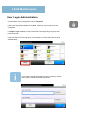
User Login Administration
A new feature of the configuration menu is My Panel.
If the User Login Administration is enabled, maximum 100 accounts can be
configured.
If Simple Login enabled, 20 user’s have their own simple login to get to their
personal screen.
If the user has an accounting name, it’s possible to connect them with the local
authentication.
If you need to get past the Simple Login you have to use the
menu button to enter the below login menu.
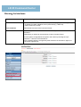
LE 05 Command Center
C t t
Contents:
• Access
• Design
• Helpful hints
• Safety concept
• Passwords
• Blocking the Operation Panel
• Blocking interfaces
• IP filter
• Local authentication
• Network authentication
At the end of the chapter you will be able to...
• integrate the device in the network.
• have an informed dialog with the administrator.
• protect the device from unauthorized network access
(flexible securityconcept).
• set up different network scan modes.
• establish administrative security functions
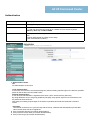
LE 05 Command Center
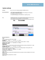
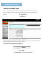
Access to the Command Center
Access to the Command Center is available via a web browser (e.g. internet Explorer, Mozilla Firefox etc.).
Enter the IP address or the host name of the printer or multifunction device in the browser's address bar.
Example:
http://192.168.100.25
htt
//192 168 100 25
or
http://KM4C3174
If the Command Center is called up, access is limited for security reasons.
Apart from setting the Command Center's language, no other settings can be made. The contents of the various
registers are limited exclusively to the display of status information.
If full access is wanted, a password has to be entered.
A click on the “Login” button calls up the registration window.
admin00
The login takes place by entering the standard password
admin00
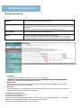
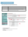
LE 05 Command Center
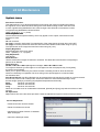
Design of the Command Center
The Command Center is divided into the following areas:
1. Main Menu
Access to the main functions of the Command Center.
If no login for the Command Center takes place, the “Start” menu appears.
2. Submenu
The contents depend on which item was chosen in the main menu.
If there is a ► after the menu item, more submenus are located there. By moving the mouse over it,
these become visible.
Each submenu is colored differently for better differentiation.
A different color is used for each submenu for better differentiation.
3. Information/setup area
The contents can be scrolled over with the right scroll bar if the setup areas are particularly extensive.
Important Note:
• If the Command Center has not been accessed for a long time, a new password has to be entered.
• It is advisable to change the access password after the first use (see page 88).
• If the password has been forgotten, there is NO way to access the Command Center. When this happens,
the
device has to be reset to the factoryy settings
g by
y taking
g the relevant measures. In this case, all individual
settings
are lost.
(Also see Command Center, "Helpful hints")
LE 05 Comman Center
LE 05 Command Center
Style of presentation in this manual
Each function of the Command Center is described in the following pages.
The presentation of nested menu structures and the corresponding screenshots have been modified
here due to space restrictions.
Example:
Danach eine Schraube des Duct Fan am linken
Rahmen lösen und die Einheit entfernen.
The presentation of the Command Center is structured as follows:
1 Submenu
The submenu is subordinate to the main menu. However, the presentation of the main menu can be dispensed
with, because the first text entry of the submenu always mirrors the main menu item.
Furthermore, all submenus are differentiated by their ground color so that each submenu can be identified easily.
Within the submenu, the menu item—the contents of which are to be presented—is indicated by a red frame.
2 Site
Sit map
The site map not only depicts the selected information or setup area, but also has a kind of position indicator
that shows the page where the user is (black entry).
If there are additional parallel pages to the selected page, then these are represented by red terms that
can be clicked on.
3 Link
If further settings are required for the selected page (function), then these are represented by blue underlined
terms.
4 More settings
The additional settings that have been clicked on in (3) are marked with an arrow. Several cascading displays
are also possible.
The rough image indicates that the illustration is incomplete and only the relevant area is shown in the
view. In practical terms this could mean that the area can only be accessed by scrolling.
LE Command
05 Command
Center
LE 05
Center
Helpful hints
Entries
All entries in the Command Center have to be confirmed using the “Send” button,
only then are the data sent to the device.
Some entries take a little time so be sure to keep an eye on the progress bar
bar.
Password
• The access password (admin00) should be changed as soon as possible so that
there is optimal protection
• In principle, it is possible NOT to define ANY password. Access to the Command
Center would then be unprotected (not recommended).
Password
forgotten/
unknown
The password can only be changed in the relevant Command Center menu. If the password is not known, the Command Center can neither be accessed nor can a new
password be defined.
The following strategy is helpful if the access password is not known:
• While installing
g the device,, a separate
p
administrator account is set up
p ((see p
page
g 96).
)
Important: The account must have administrator rights!
• This administrator account can be used to access system settings via operation panel.
• Local authentication can be activated via the system settings.
• After that the administrator account can be used to acccess the Command Center.
• Though the password has not been changed
changed, all settings in the Command Center are
available.
• After making the required settings, local authentication (in the Command Center)
can be switched off again.
A password change, when the old password is not known, can only be carried out by
resetting the device:
• Reset via the Command Center
"Reset to factory settings" results in the loss of certain data. Make sure that
these data are saved before the reset is carried out.
LE 05 Command Center
LE 05 Command Center
Safety Concept
Requirements
Measure
The device's system settings
have to be protected.
The system settings are protected by a standard account (DeviceAdmin)
(FS-6025: 2500 / 2500 and FS-6030: 3000 / 3000
This standard account should be changed as required to ensure long-term
security.
It is also practical to set up an additional account to ensure access if the
"official“ password is lost or unknown (should be arranged with the
customer).
In addition to system settings,
any unauthorized device
configuration
should generally be
prevented
prevented.
See page Authentication
System settings must be
protected from access via the
Command Center.
Access to the Command Center is protected by a standard password
(admin00). This standard password should be changed as required to
ensure long-term security.
It is also practical to set up an additional account (see User Login) to
ensure access if the "official" password is lost or unknown.
Only selected communication
protocols must be used.
See page Network safety
Only certain interfaces must
be used.
See page Blocking the Interfaces
Only certain PCs must be allowed
to access the device.
See page IP-Filter
Access to the device / Command
Center must only be
granted to certain persons.
Local Authentication
Specific use of the device is
granted to certain persons.
Local authentication linked to a cost center.
LE 05 Command Center
LE 05 Command Center
Device safety
Measure
The start page is the starting point for various settings to increase the network's
operational dependability.
Recommendations
Part of a security concept.
Pre-conditions
Administrative access to the Command Center.
Notes
On this start page, the relevant areas are briefly explained. By clicking on the
underlined terms the desired setup area can be reached.
Some settings require, where necessary, a network administrator's presence.
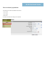
LE 05 Command Center
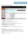
Change password
Action
Password change for accessing the Command Center.
Recommendations
• Access to the Command Center should generally be protected.
• The password should be changed at regular intervals.
• Part of a security concept.
Pre-conditions
Administrative access to the Command Center.
Notes
If the password has been forgotten, the only option is to reset to the factory
settings. All network and authentication settings are thereby lost.
LE 05 Command Center
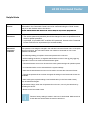
Blocking the operation panel
Action
Blocking the system menu of the device.
Recommendations
• If arbitrary system settings and system changes are to be prevented.
• If specifically qualified personnel is responsible for maintaining the device.
• Part of a security concept.
Pre-conditions
Administrative access to the Command Center.
Notes
• In the locked status, access to system settings is possible from the operation
panel with the help of the administrator account.
Partial blocking:
In case of partial blocking, access to the device's system menu is only possible with the
Device Admin account (2500 / 2500 or 3000 / 3000).
Locking:
Like partial blocking.
In addition, the STO P button does not have any function anymore.
Running processes can no longer be interrupted / cancelled.
In addition, deleting jobs in the queue is no longer possible.
LE 05 Command Center
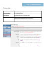
Blocking the Interfaces
Action
Targeted blocking of the device's interfaces.
Recommendations
• If unauthorized use of the device is to be prevented (e.g. to print holiday photos).
• If arbitrary firmware updates are to be prevented (e.g. USB host).
• Part of a security concept.
Pre-conditions
Administrative access to the Command Center.
Notes
• After setup, the device has to be switched off briefly so that the status can be
activated.
Alternatively, a restart can be carried out via the Command Center.
If a fax system is integrated in the system, this is done by blocking the "Opt.
interface 1" causes it to be switched off.
As the interface status
stat s is changed only
onl after the device
de ice is switched
s itched on again,
again the
causal link might be lost.
LE 05 Command Center
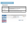
Network safety
Measure
Targeted activation of transfer protocols.
Recommendations
• Only those protocols should be activated that are required for communicating
with the device.
• Part
P t off a security
it concept.
t
Pre-conditions
Administrative access to the Command Center.
Notes
After the settings are made, the network interfaces have to be re-initialized
LE 05 Command Center
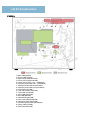
IP-Filter
IP
Filter (v4 and v6)
Measure
Setup of exclusive communication addresses
Recommendations
• Only very specific computers may connect to the device.
• Only a very specific address range may communicate with the device within the
network.
t
k
• When communicating, the device may only use specific protocols.
Pre-conditions
Administrative access to the Command Center.
Notes
• This page is linked to the menu "Basic/device security".
• A total of ten filters is available, that can be set independently of each other.
• After the settings are made, the network interfaces have to be re-initialized.
1
IP address
IP address of the computer with which the device is to communicate.
Depending on the definition of the subnet mask, the segment address that is entered determine the
kind of communication that is allowed with the device.
2 Subnet mask
Depending on the entry of the IP address, the subnet mask defines the area (segment) within which
communication with the device is possible.
3 Protocols
The above settings are only applicable for the protocols that have been marked. Protocols that have not
been marked are excluded from the communication!
C f
Configuration
example ((IPv4):
4)
IP address: 192.168.100.xxx (x=any)
Subnet mask: 255.255.255.0
All computers within the address area of the IP: 192.168.100.1 to IP: 192.168.100.255 may communicate
with the device (provided that at least one protocol has been marked).
All other computers are excluded from communicating.
LE 05 Command Center
Authentication models
No authentication
Admin / Admin
admin00
• Administrative access to the
Command Center with ONE
password *).
• Generally open access*).
• No personal access (only password).
• Access limitations possible via
cost center mode.
• Unprotected access possible.
•For security reasons, administrative access to the Command Center in the factory default settings is protected.
•For security reasons, access to vital system settings via the operation panel is also protected:
System menu:
• System
• User/ Job Accounting
Factory default settings allow access to these areas via the following (standard) accounts:
(<Name> / <Password>)
2600 / 2600
-orAdmin / Admin
LE 05 Command Center
Authentication models
Local authentication
max. 200 accounts
• General access barrier to the Command Center
and device.
• Personalized access (ID and password) for
Command Center and device.
• Access restrictions via user status (administrator/ user)
possible.
• Cost Centers can be linked to the registered
account.
Up to 100 user accounts can be set up via the Command Center and via the operation panel.
2 different user statuses (administrator or user) determine the account holder's access rights.
While the administrator has full access to the Command Center and the device's system settings, access for user
status is severely restricted.
The restrictions are noticeably greater than with systems that are not subject to authentication.
Important:
If the device is operated as a printer, the authentication (login-username and login password) has to be entered in
the device settings of the printer driver, otherwise printing is denied.
LE 05 Command Center
Authentication models
Network authentication
Server
ADS
User accounts
in ADS
max. 50 groups
• General access barrier to the Command Center
and device.
• Personalized access (ID and password) for
Command Center and device.
• Access restrictions via user status
(administrator / user) possible.
• By using group authorization, certain rights
can be assigned to the account for the use of
the device.
ADS (Active Directory Services) has to be available.
The user accounts are centrally provided on the server in the AD S (Active Directory Service).
The authorization group is assigned to the user account via the group ID .
The configuration of the group profile results in the access profile of the account.
LE 05 Command Center
User login (user authentication)
Action
Creating personalized accounts (local).
Recommendations
• Only certain persons may administer the cost centers.
• Only certain persons may apply administrative settings to the device.
• Only certain persons are allowed to have administrative access to the Command
Center.
Center
• Only certain persons may use the device.
• Certain persons are subject to limitations (copy, scan, print etc.)
Pre-conditions
Administrative access to the Command Center or administrative access to system
settings of the device.
Notes
• The standard account (Admin/Admin) is set up and cannot be deleted. After
installing
the device,
device the password of this account should be changed for security reasons
reasons.
• The user accounts for login can also be used for the device's system settings
(only in the case of administrator status).
• A max. of 100 local accounts is possible.
• For further information, see paragraph “Authentication”
1
2
3
4
5
Full name of account holder.
Login name that is to be entered in the computer or the device's operation panel.
Password, enter twice for security control.
E-mail address of the account holder is used in certain cases for notification and identification purposes.
A cost center can be assigned to the account holder so that for local authentication (see page 94) the
criteria of this cost center (counting, limitations, allocations etc.) are automatically linked to this user.
6 Status of the account holder:
User:
No administration and system configuration is possible at the device and Command Center.
Administrator:
Full administrative access to the device and Command Center is possible.
LE 05 Command Center
Authentication
Action
Specifying the authentication
Recommendations
When generally a person-specific authentication is wanted for the device.
Pre-conditions
• Administrative access to the Command Center
• Local user accounts (see page 94) or network accounts via AD S (Active
Di t
Directory
S
Services)
i
) mustt be
b available.
il bl
Notes
As very detailed knowledge of networks is required for this, it is recommended that
the
network administrator is present for the setup.
(See “Authentication models”)
1 Authentication mode:
Off:
No authentication via accounts.
Local authentication:
If local user accounts are to be used (see page 94), then this setting requires login on the device's operation
panel as well as within the Command Center.
Network authentication:
If user account administration is organized via a server (AD S, Active Directory Services).
By using definitions of up to 20 group guidelines (see page 100), specific rights for use of the device can
be granted to these accounts.
After setup, this setting requires login on the device's operation panel and also inside the Command
Center.
Center
Important:
The internal clock has to run synchronously with the server, otherwise the authentication process fails.
Hence a time server has to be registered.
2 Entry of network domains (for network authentication).
3 Entry of the AD S host name (for network authentication).
4 Entry of server type (for network authentication).
LE 05 Command Center
Authentication administrator status
Authentication,
Full access to the Command Center and to the device's system menu.
LE 05 Command Center
Authentication user status
Authentication,
Limited access to the Command Center and to the device's system menu.
LE 05 Command Center
Group authorization (for network authentification)
Action
Mapping a user profile for network authentication.
Recommendations
When different personalized access rights to the device are desired.
Pre-conditions
• Administrative access to the Command Center.
• Network access via AD S (Active Directory Services) has to be available.
Notes
As very detailed knowledge of networks is required for this, it is recommended that
the network administrator is present for the setup.
1
2
3
4
1 Group authorization switch on/off.
2 Group ID (numerical entry).
An account is assigned to this ID in the ADS (Active Directory Service).
3 Group name.
Serves for identification of the group by name.
4 Profile settings.
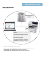
LE 05 Command Center
Scan via network
network, preparations
The following scan modes are available via the network:
• Scan to email
• Scan to SMB
• Scan to FTP
For these scan modes, basic settings can be specified.
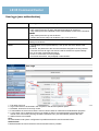
LE 05 Command Center
S
Scanning,
i
Scan-to-Email
S
t E il
Action
Scan to e-mail accounts.
Recommendations
fÑ=íÜÉêÉ=áë=~=êÉèìáêÉãÉåí=Ñçê=ëÉåÇáåÖ=ëÅ~ååÉÇ=çÄàÉÅíë=îá~=ÉJã~áäK
Pre-conditions
√=^Çãáåáëíê~íáîÉ=~ÅÅÉëë=íç=íÜÉ=`çãã~åÇ=`ÉåíÉêK
√=bJã~áä=ëÉêîÉê=Epjqm=ëÉêîÉêF=áë=~ÅÅÉëëáÄäÉ=îá~=íÜÉ=åÉíïçêâK
√=i~êÖÉ=~íí~ÅÜãÉåíë=EÖê~éÜáÅëF=ã~ó=ÄÉ=ÇÉéçëáíÉÇ=áå=íÜÉ=ÉJã~áä=ëÉêîÉêK
i
íí Ü
í E
Üá F
Ä Ç
áí Ç á íÜ
áä
Notes
qÜçìÖÜ=~ÇÇêÉëë=ÉåíêáÉë=Å~å=ÄÉ=ã~ÇÉ=îá~=íÜÉ=çéÉê~íáçå=é~åÉäI=áí=áë=êÉÅçããÉåÇÉÇ=
íÜ~í
í~êÖÉí=~ÇÇêÉëëÉë=~êÉ=ëíçêÉÇ=Ñçê=íÜáë=ÇÉîáÅÉK
qÜáë=Å~å=ÄÉ=ÇçåÉ=îá~=íÜÉ=~ÇÇêÉëë=Äççâë=EëÉÉ=é~ÖÉ=NMSF=çê=Äó=ìëáåÖ=íÜÉ=çåÉ=íçìÅÜ=
âÉóëK
1
2
3
4
5
6
1.
2.
3.
4.
5.
6.
E-mail Basic Settings (Re and Body Text)
SMTP protocol status. For Scan-to-Email, the protocol must be activated!
Mail server connection parameter (IP address or host name)
Mail-Server Authentication (optional)
E-mail account for mail server authentication (only if authentication is required)
Test connection to mail server (should be confirmed by the system with "OK")
LE 05 Command Center
S
Scanning,
i
Scan-to-Email
S
t E il (continued)
(
ti
d)
1
2
3
4
1. If the preset size limit is exceeded, the scan aborts with an error message and the file is not transferred.
2. Entering the sender's address is mandatory (!), otherwise Scan-to-Email cannot be carried out. For practical
purposes, the sender's address should be an active address so that, for example, there is a reply to the scan email.
3. The signature can be a text or a so-called object string (variables, the provide certain information).
4. Domains, that are entered in the list (e.g. "kyoceramita.de") serve as a control for free address entry for Scanto-Email.
For example, some domains may be explicitly prohibited ("reject") or may be used exclusively ("accept").
Summary
• Activate SMPT protocol (!)
• The mail server must be accessible via the network. For gateway connections timeouts have to be
taken into account (extended, if necessary).
• Keep potential server authentication in mind.
• Carry out test connection.
• Enter sender's address (!)
• Set mail limit, if necessary (consult administrator).
• Make
a e meaningful
ea g u e
entries
t es for
o "Re:",
e , "Body
ody Text"
e t a
and
d "Signature".
S g atu e
• In case of manual input of mail addresses (at the device operation panel), specify domain limitations,
where necessary.
LE 05 Command Center
S
Scanning,
i
Scan-to-FTP
S
t FTP
Action
Scan to FTP recources
Recommendations
If there is a requirement for sending scanned objects via FTP transfer
Pre-conditions
• Administrative access to the Command Center.
• FTP resource (FTP server) can be accessed via the network.
Notes
Though address entries can be made via the operation panel, it is
recommended for this device that the FTP target addresses are stored.
This can be done via the address books or by using the one touch keys.
Summary
• The FTP protocol must be switched on.
on
• The port addresses can be edited as needed.
• FTP encryption (FTP over SSL) is supported optionally, if the FTP resource allows it.
LE 05 Command Center
S
Scanning,
i
Scan-to-SMB
S
t SMB
Action
Scan to Windows Services (e.g. in folder)
Recommendations
If there is a requirement for sending scanned objects To Windows Services
Pre-conditions
• Administrative access to the Command Center.
• Services can be accessed via the network.
Notes
Though SMB address entries can be made via the operation panel, it is
recommended that target addresses for this device are stored.
This can be done via the address books or by using the one touch keys.
Summary
• The SMB protocol must be switched on
on.
• The port adresses can be edited as needed.
• Check by means of a PC that the relevant rights have been assigned to the services that will receive the scans.
Transfer the required information (account, password etc.) to the address book.
• If the computer receiving the scan is part of a domain, then the user entry for the scanner has to be the
corresponding domain name. The login user name is (for example):
<domain user name>@domain.local.
• The firewall settings may have to be modified, if this is required ("file and printer sharing").
LE 05 Command Center
S
Scanning,
i
Send
S d and
d forward
f
d
Action
Forward a sent file to a specified destination
Recommendations
If there is a requirement to control sent documents.
Pre-conditions
• Administrative access to the Command Center.
• Customer setup is depending on receiver for E-mail, FTP and SMB.
Notes
LE 05 Command Center
Add
Address
book,
b k local
l
l
Action
Setting up a local address book for selection of scan and fax destinations.
Recommendations
If scanning and faxing are always to be used for the same destinations.
Pre-conditions
Administrative access to the Command Center.
Notes
• Address entries are stored in the device in question.
• Via U-917 these entries can be stored on a USB device and transferred to
another FS-6025/6030MFP or FS-C8020/8025MFP
• Via the KM NetViewer (5.x), these entries can also be stored on a PC and
transferred to other devices.
1.
2.
3.
4.
5.
Link for adding
g address book entries.
Position and name entry of the record.
E-mail based address data (for Scan-to-Email).
SMB based address data (for Scan-to-SMB).
FTP based address data (for Scan-to-FTP).
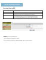
LE 05 Command Center
S di service
Sending
i lists
li t
By means of the following entry in the browser's address bar:
http://<IPAdress>/svcmntrpt
an HT ML page is called up that can be used to send specific service reports via e-mail.
1
2
3
4
5
6
7
1 Mail address to which the desired reports
p
can be sent ( as attachment).
)
2 Automated terms (strings) that appear in the subject line.
3 Option for the relevant list(s).
4 File format of the list (HT ML or TXT).
5 Activation of the body text.
6 Time interval for the regular transmission of lists (optional).
7 Send button for one-time
one time and immediate transmission of the lists
lists.
Important Note:
For the above function the STMP settings (mail server settings) have to be complete.
LE 05 Command Center
Add
Address
book,
b k local
l
l
Action
Reset / restart
Recommendations
• With network settings via the Command Center
• Where there are changes to the status of interfaces via the Command Center
• When a reset to the factory settings is desired
Pre-conditions
Administrative access to the Command Center.
Notes
When selecting, different functionalities have to be taken into account
1
2
3
1
Restart
Is identical to switching the device off and on.
2
Initializing the network connection
All changes to the network settings in the Command
Center require these measures.
While the reset takes place, the copier can be used
without restrictions.
3
Reset to factory settings
All settings relating to networks are reset to factory settings or deleted.
The passwords are also reset to the standard ones.
Display language is reset to English.
Note:
Address entries and user accounts (for local authentication) are preserved.
Blank Page
If yoU hAve ANy qUestIoNs...
coNtAct Us!
Do you require information about the training or one of our detailed information brochures
about individual training programs?
Contact us at:
[email protected]
Or visit our website:
http://www.kyocera-academy.de
Kyocera Academy
Otto-Hahn-Str. 12
D-40 670 Meerbusch
uprint ucopy uscan ufax