1
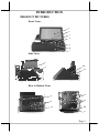
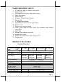
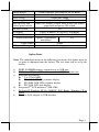
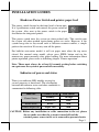
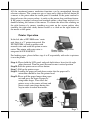
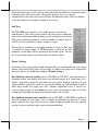
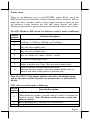
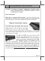
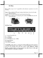
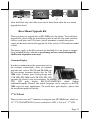
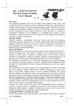
XP-2000 Series
Fan Free Touch Terminal
User’s Manual
Rev.: A0
FCC Notes:
This equipment generates, uses, and can radiate radio frequency energy and, if not installed and
used in accordance with the instructions manual, may cause interference to radio communications.
It has been tested and found to comply with limits for a Class A digital device pursuant to subpart
J of Part 15 of FCC Rules, which are designed to provide reasonable protection against
interference when operated in a commercial environment. Operation of this equipment in a
residential area is likely to cause interference in which case the user at his own expense will be
required to take whatever measures to correct the interference.
Warranty Limits:
Warranty terminates automatically when any person other than the authorized technicians opens
the machine. The user should consult his/her dealer for the problem happened. Warranty voids if
the user does not follow the instructions in application of this merchandise. The manufacturer is by
no means responsible for any damage or hazard caused by improper application.
About This Manual:
Posiflex has made every effort for the accuracy of the content in this manual. However, Posiflex
Technology, Inc. will assume no liability for any technical inaccuracies or editorial or other errors
or omissions contained herein, nor for direct, indirect, incidental, consequential or otherwise
damages, including without limitation loss of data or profits, resulting from the furnishing,
performance, or use of this material.
This information is provided “as is” and Posiflex Technology, Inc. expressly disclaims any
warranties, expressed, implied or statutory, including without limitation implied warranties of
merchantability or fitness for particular purpose, good title and against infringement.
The information in this manual contains only essential hardware concerns for general user and is
subject to change without notice. Posiflex Technology, Inc. reserves the right to alter product
designs, layouts or drivers without notification. The system integrator shall provide applicative
notices and arrangement for special options utilizing this product. The user may find the most up
to date information of the hardware from: http://www.posiflex.com or http://www.posiflex.com.tw
or http://www.posiflexusa.com
All data should be backed-up prior to the installation of any drive unit or storage peripheral.
Posiflex will not be responsible for any loss of data resulting from the use, disuse or misuse of this
or any other Posiflex product.
All rights are strictly reserved. No part of this documentation may be reproduced, stored in a
retrieval system, or transmitted in any form or by any means, electronic, mechanical, photocopying,
or otherwise, without prior express written consent from Posiflex Technology, Inc. the publisher of
this documentation.
© Copyright Posiflex Technology, Inc. 2009
All brand and product names and trademarks are the property of their respective holders.
P/N: 15460900020
ALERT TO OUR HONORABLE CUSTOMERS:
Please always read thoroughly all the instructions and documents delivered
with the product before you do anything about it. Don’t take any premature
action before you have a full understanding of the consequences.
DAILY MAINTENANCE GUIDE
For regular cleaning of the XP systems, please use only soft haired brush or
dry soft cloth. You may use moist soft cloth to remove stains when necessary.
Apply only suitable amount of mild neutral cleaner for obstinate stains. Please
note that never use Acryl dissolving solvent or Polycarbonate dissolving
solvent. You may apply ammonia-based glass cleaner only on the screen
surface.
ABOUT THIS PRODUCT
Posiflex XP-2000 series presents a whole new generation POS terminal, which
is a combination of touch screen, printer, MSR, and the most reliable FanFree
structure. This integrated solution of XP-2000 series not only less cable
connection, but also carrying a brilliant performance to user in order to face
the busiest situation.
XP-2000 Series applies Intel Celeron M technology; fast speed Ethernet as
well as plenty of connects ports of USB, Serial, VGA and CR ports. It also
integrated with thermal printer, touch screen and MSR, as well as designed
with gorgeous appearance and small footprint for counter space saving. The
small and fully integrated system is suitable for many kinds of segments, such
as general retailer, hospitality and restaurant. In addition, XP-2000 series
terminal assist small and medium business to serve customer effectively,
speedy and precise.
All-in-one integrated system including touch screen, thermal printer and
MSR which is the best choice of ECR Replacement.
Integrated thermal printer with paper jams easy to fix design.
One touch power ON/OFF design provides convenience control for
terminal and printer.
The most reliable Fanfree structure for harsh environment.
Support Win XP Pro, POSReady, WEPOS, Windows CE and Linux
environment
Vertical type LCD panel with easy tilt angle adjustment
Supports SSD (Solid-State Drive) Data Storage Device or HDD
Page 1
INTRODUCTION
PRODUCT PICTURES
Front Views
1
2
3
4
5
6
7
Side Views
8
10
9
11
Rear & Bottom Views
9
14
12
15
13
16
17
Page 2
PARTS IDENTIFICATION
1.
2.
3.
4.
5.
6.
7.
8.
9.
10.
11.
12.
13.
14.
15.
16.
17.
LCD display with or without touch panel
Printed paper exit
LED indicator for power and printer status
Paper feed button
Power switch
Magnetic Stripe Reader(Option)
Base Stand
LCD adjustable Holder
Lock/Release button for tilt angle adjust
Printer cover
Printer cover release button
Three screw holes in back cover for customer pole display
integration
Cable Exit
Bottom plate compression lock
Bottom plate tenon
Rubber foot with bottom plate fixing screw
Bottom plate
PRODUCT FEATURES
Standard Features:
Models XP-2007
Item
CPU
VGA port
LCD DISPLAY(TFT Digital 7"
LCD Panel )
(800x600
resolution)
DRAM Memory
Serial port
CR PORT
Standard USB PORT
AUDIO PORT
ETHERNET port
TOUCH function
N/A
TOUCH SENSOR
N/A
XP-2008H XP-2010H XP-2012H
Intel Celeron M 600Mhz
D-SUB 15Pin
Digital 8"
Digital 10. 4" Digital 12.1"
(800x600
( 800x600
( 1024x768
resolution) resolution) resolution)
DDR-II(SO-DIMM X 1)
1, DB9 X 1 on the I/O Plate
X1
4 port on the I/O plate
buzzer only
10/100 MB
USB Interface
5 Wire Touch Pad
Page 3
Storage device
DOM (Optional SSD HDD or SATA HDD)
Power switch
On the front bezel
Power saving
Suspension mode
Power supply
power adaptor, 60W
Indicator LED and
Power ON/ standby, Printer Error /Paper Out (RED),
Control panel switch
paper feed and power ON switch.
Fan-Free system
Yes
OS support
Linux, Window CE. WEPOS. POSReady
Printer build in
2" thermal printer (60mm/sec, MAX)
Printer auto cutter Option (Upgradeable
Yes
auto cutter)
Paper Width
58mm
LCD panel tilt angle
14~55 (degree)
Table: Summary of features
Option Items:
Note: The underlined items in the following list means that option must be
set prior to shipment from the factory. The rest items can be set by the
dealers.
a)
b)
c)
d)
e)
f)
DDR2 SODIMM memory expansion up to 2GB max.
HDD kit or SSD kit (SSD can’t coexist with HDD in main unit).
Integrated upgrade kit:
2 or 3 track MSR.
PD-330, 2x20 LCD customer display.
PD-2606, 2x20 VFD customer display.
PD-7630, LCD pole display.
Integrated 2nd LCD monitor 8”(LM-2208)
Preload OS Windows XP Pro WEPOS, POS Ready, Windows CE or
Linux
Wireless LAN adaptor in USB interface
Page 4
INSTALLATION GUIDES
Hardware Power Switch and printer paper feed
The power switch located in the front bezel of main unit.
It is a pushbutton switch and controls the power on/off of
the system. Also, next to the power switch is the paper
feed button for integrated printer.
This power switch turns the system on when pushed only. This switch turns
the system off when pushed again during power on status. However, if the
system hangs due to any reason such as software resource conflict, a simple
push on the switch in 10 sec may turn off the power.
For build-in auto-cutter model, it will cut paper once when the top cover
closed. For manual cutter model, please press FEED button and rip the
unnecessary paper manually after paper loading. For more information about
printer operation, please refer to following chapter “Printer operation”.
Note: There must always be at least 10 seconds waiting before switching
on again once the system is powered off successfully.
Indicators of power and status
There is an indicator LED module serving for
several purposes at front bezel. The relationship
between the indicator status and other conditions is
summarized in following table:
Indicator
Terminal Status
LED colour
Standby
Orange
Power On
Blue
Printer Error
Error
Red
Printer Paper Out
Paper Out
Red
Power Status
CAUTION: Before any installation or cable connection to the set, please
always make sure that the system is turned off and the
external power source to the set is removed to prevent electric
Page 5
hazard! Never touch any metal pin in the connectors or
circuits to avoid high voltage hazard or electrostatic discharge
damage unless the operator is well grounded. Failure to do the
above will void the product warranty!
Display Issues
Main LCD Display
For best viewing result, please set your display resolution at 800 x 600 for 7”,
8” and 10” LCD, as well as for XP-2012H is 1024 x 768. The system Video
Memory is shared from system memory. XP-2000 series support DVMT
Function and the video memory size is default in 128 MB and can be set to be
64 MB.
VGA Port
The VGA port in the XP-2000 system supports either a rear mount 2nd display
or a separately connected LCD monitor or touch monitor. To support the DC
power to the 2nd display monitor, it required a qualified technician to set an
internal jumper in XP main unit. To supply the necessary power through the
VGA connector, please refer to the Posiflex technical information. Do not
connect other monitor to this port before the power in this port is disabled.
Posiflex USB Touch Manager
A program named “Posiflex USB Touch Manager” and a right-click sticky
button tool in the program group “Posiflex USB Touch Tools” is installed in
the preloaded Windows system with a USB interface touch panel controller.
This program can also be obtained by download from the POSIFLEX web site.
Mouse Emulation
The touch panel in XP-2000 system uses internal USB
interface as standard and occupies no external port.
When the touch driver is properly installed, this touch
panel works exactly like a standard mouse for each interface. Nevertheless, if
the system is running under safe mode, the touch panel calibration may
become unsatisfactory due to disabled drivers. It is recommended to use a
standard USB mouse or keyboard in this mode.
Page 6
All the mentioned mouse emulation functions can be manipulated through
relevant software. The system can give a beep and a click on the left button of
a mouse at the point when the touch panel is touched. If the point touched is
dragged across the screen surface, it works as the mouse drag and drop feature.
If the point is touched, released and touched within a short time interval, it is
double-clicking left button of the mouse. To obtain the effect like clicking on
the right button of a mouse, touching any point on the screen surface after
touching the right-click sticky button results as a click on the right button of
the mouse at that point.
Printer Operation
In the left side of XP-2000 series’ main
unit, there is a 2” printer integrated. For
XP-2007/2008, it built-in printer with
manual cutter and could be option an autocutter. The printer with auto cutter is
integrated in XP-2010/2012.
Printer cover Paper Exit
release button
For loading paper, please follow step A to F sequentially with refer to pictures
to use the printer.
Step A: Please hold the LCD panel and push lock/release lever for tilt angle
adjust forward. Turn the panel forward to most vertical position
Step B: Push the printer cover release button.
Step C: Pull up the printer cover.
Step D: Loading the paper roll and please notice that the paper roll’s
orientation should be face the printer head.
Step E: Please pull the paper longer then paper
A
exit and press the front of paper by
A
using index finger. Then close the
printer cover at the centre of front and
please watch your finger during this
step in order to reduce hurt occur.
D
B
C
E
C
Page 7
After finished steps A to E, please notice that the dissimilarity of manual cutter
and auto cutter. For auto cutter, the printer will cut the excess paper
automatically after the paper cover closed. For Manual cutter, user can choose
to rip the unnecessary paper by hand or not to rip.
Self Test
For XP-2000 series printer’s test mode, please turn off the
terminal first. After the system power off, please press and hold
down the feed button while turning on the system power switch.
The printer will then perform a self-test mode. A sample slip of
self-test result is printed as in the sample at right.
The header is printed in text mode and the rest part of this slip
is printed in page mode. If FEED button is pressed at this
moment, a font table will be printed in text mode again. To exit
the test printing, please turn the printer off and on again.
Paper Cutting
Generally, after paper printed and automatically cut or manually rip every time,
printer will retract the paper roll in order to reduce the paper loss (adjustable
function, please see following chapter “Printer setup”).
For build-in auto-cut models such as XP-2010 or XP-2012, once the auto-cut
function enable, the printer will leave the advance paper in 4.8 mm long. It is
highly suggested to print the logo and necessary paper feeding to make 4.8 mm
paper advance right after each cut to prevent curling up and jamming of paper
front edge inside the paper exit slot. Another important issue is please set
every receipt length at least 6cm for every auto-cut model in order to let the
receipt pass through the paper exit channel and easily to take.
For build-in manual cutter models such as XP-2007 or XP-2008, in order to
prevent curling up and paper jam, it highly recommend to reserve 4.8 mm
paper advance for logo and necessary paper feeding length. For the printed
receipts, please rip them right after each print finished.
Page 8
Printer setup
There are two difference way to setup XP-2000’s printer. Firstly, one is the
DIP Switch inside of terminal for setup the function such as baud rate, Full-cut
mode and others. Another switch is setup trough software to adjust not only
the hardware switch function but also add printer density and others.
Following explanation is going to descript each function of these two switches.
The SW1 Hardware DIP switch 1 or Software switch 1 works as following:
Switch
Function description
position
Baud rate definition. There are four speed can be choose which are
1
19200 bps, 115200 bps, 9600 bps and 38400 bps.
2
Control paper auto-cut when cover close and switch on the printer
3
(For auto-cutter models only).
Full-cut mode or Partial-cut mode choice
4
(For auto-cutter models only).
5
Busy on “buffer full” and/or “off line” control
6
Cut with or without paper feed.
7
Enable or disable auto Cutter. (For auto-cutter models only).
8
Enable or disable back feed 6mm before print
(For manual-cutter models, auto-cutter models disable auto-cut
function and when enable partial cut function only).
Note: For SW1-7, if the printer build-in auto cutter, the default setting
will be auto-cutter enable. If printer use manual cutter, it will default at
disable.
SW2 software switch works as following:
Switch
Function description
position
Set Hardware Switch 1 Valid or Invalid.
(When hardware switches 1 invalid, software switch 1 can instead of
1
hardware switch 1. Note: Hardware switch can not co-work with
software switch)
Raster Bitmap Print by line print or by buffer batch.
5
Even parity or None parity
6
Page 9
7
8
XON/XOFF handshaking or DSR/DTR handshaking
CR code (0Dh) effective or invalid
CAUTION: On doing any function’s modification of switches, please
contact authorized dealer or technicians. Failure to do this
could damage the terminal.
Paper Jam Problems
When Paper is jammed inside the printer – Push down the hood release
button then the top hood can be released. Remove the jammed paper and
reinstall the paper roll. Close the hood properly and firmly for operation.
Magnetic Stripe Reader (Option)
For magnetic stripe card reading, please insert the
card to the bottom and magnetic stripe facing the
marked aside of slot. In spite of the card’s
movement can be two-way of the slot, the reading
process should be passing through whole slot horizontally. A non-standard
card recorded without complete degaussing prior to recovery may accept only
one direction in card reading.
The MSR in XP-2000 series reads the ISO or JIS-II
magnetic stripe card without driver. Yet, there is a
“Posiflex USB MSR Manager” program provided to
control some parameter configuration for ISO MSR.
The controllable features in this program covered:
each track enable/disable, Alt+Num approach for ASCII codes and
Leading/Stop code enable/disable. The function for enabling each track comes
in effect only when the track is physically available. Please find in the Product
Information CD delivered with system “\Drivers\SD_Series\USBMSR_xxx”
and “Set Up” this manager program or download the installation program from
our official website http://www.posiflex.com or http://www.posiflex.com.tw.
Page 10
I/O Plate
Please follow steps A to C sequentially with reference to pictures to use the
I/O Plate.
Step A: Please hold the LCD panel and push lock/release lever for tilt angle
adjust backward.
Step B: Turn the panel backward to most horizontal position
Step C: Please hold the base and pull up the terminal carefully than you will
see the I/O plate.
A
B
I/O
C
I/O Plate View:
A
B
C
D
E
F
G
A: 1x Serial Port (RS-232).
B: 4x USB Ports.
C: 1x LAN Port.
D: 1x VGA Port (D-sub, 15 PIN).
E: Service Window.
F: 1x CR Ports.
G: DC Power connecter.
In XP-2000 system, there is a serial port in form of DB 9 pin male connectors
available in the I/O plate. It can supply a +5 V DC through pin 9 of serial port
and +12V DC through VGA port after jumper setting. However, except
Posiflex peripheral device, do not connect any other device to this port
before the power in this port is disabled.
Page 11
CAUTION: Please turn off the system power first! Then hold the base and
move the terminal carefully.
Connecting Cables
To have the terminal ready for operation, please connect all required cables to
the appropriate connectors. Please make sure that each connector is connected
to the correct port with the correct orientation. Damages due to incorrect
connection or orientation are not covered by product warranty!
Some connectors like the LAN or CR connector have to be gently inserted
until a click is heard. It is recommended that connectors such as the COM port
and VGA connector be screwed into place once seated. Please make sure that
each connector has to be connected to the right device in the right way.
CAUTION: On doing any insertion or extraction of any connector, please
always hold the connector head itself instead of pulling on the
cable wire. Failure to do this could damage the cable and jack
that is considered as an artificial destruction and is not
covered by the warranty.
Preparing the Main Unit
On the back of the I/O Plate, there is a service window among the 1 matching
screw. Remove the service window lock screw to find several jumpers. The
jumpers in this window are designated for USB Touch, VGA & COM port
power and hardware reset functions. Please consult your dealer for technical
support on setup of these jumpers. Please notice that only those qualified
technicians may adjust in the service window with information from Posiflex
and the contents in the service window may change without notice as time
develops. Before install the rear mount upgrade kits such as customer display,
there is one step needs to do. Please release the cable exit cover as following
steps:
A: Please find the back of cable cover which just near the I/O plate.
B: Please use the Fingertip to release compression lock.
C: after the cable cover released, please cut the circle part which show in the
picture C.
Page 12
A
B
C
After finish this step, the cable cover can be fixed back when the rear mount
upgrade kits fixed.
Rear Mount Upgrade Kit
There are plenty of upgrade kits of XP-2000 series for choice. To install these
upgrade kits, please refer the installation guide of each kit. For some interface
such as serial ports and VGA ports, please remember to enable the power
supply of the main unit for the upgrade kit if the serial or VGA interface model
is used.
The power supply in the I/O port must be disabled if it is no longer to support
these intended devices otherwise any damage or loss caused consequently
shall be out of product warranty!
Customer Display
In order to communicate the transaction total to
the customer conveniently, there are optional
upgrades kits such as PD-330 and PD-2606 are
the rear mount customer display kits for XP2000 series. Counter space saving design with
2*20 VFD (PD-2606) and 2*20 LCD (PD-330)
provides the clearest view for customers. In addition, real base mount graphic
STN LCD pole display PD-7614/7624/PD7634 which support
traditional/simplify Chinese and Arabic language can be integrate to the XP2000 series for more applications. To install these pole displays, please refer
the installation guide of each kit.
2nd LCD Panel
There are two sizes of 2nd monitor can integrate into XP-2000 series which are
12” 2nd LCD LM/TM-2212(screen resolution is 1024 x 768) or 8” 2nd LCD
Page 13
LM-2208 (screen resolution is 800 x 600). TM-2212 is a 12” LCD touch
monitor which can mount a magnetic stripe reader for customer use to.
The VGA port in the XP-2000 system supports either a
base mount 2nd display or a separately connected LCD
monitor or touch monitor. To support the DC power to
the 2nd display, it required a qualified technician to set
the power supply in XP main unit through the VGA
connector according to Posiflex technical information.
Do not connect other monitor to this port before the
power in this port is disabled.
Note: When 2nd display is connected, the screen display of system boot up
stage and application in some OS will be smaller than usual in both 1st and
2nd displays.
Connecting Cash Drawer (Option)
The RJ11 connector in I/O area of a XP-2000 system can be used for
controlling most of the common cash drawers available on the market.
However, it is most recommended to use Posiflex CR-2000 or CR-2200 or
CR-3100 or CR-3200 or CR-4000 or CR-4100 or CR-4210 or CR-6310 for
best compliance to operate the opening mechanism and to monitor the drawer
open status.
Use the cable supplied with the cash drawer for connection to the CR port in
XP system. This cable has a 6-pole plug at one end and an 8-pole plug at the
other. The 8-pole plug should be inserted into the connector marked: “signal
cable from POS Printer” at the rear of the cash drawer. The 6-pole plug should
be inserted in the connector marked “CR” found in the main connection area in
the system.
System Recovery
For XP systems preloaded with Windows WEPOS / POS Ready / Windows
CE / Linux on DOM, HDD or Solid State Drive, Posiflex provides recovery
DVD delivered with the terminal for the preloaded operating system. The
System Integrator shall take care of software restoration after OS
recovered. A Posiflex supplied USB interface DVD drive will be required for
Page 14
such action. Other brand DVD-ROM drive may require its own driver different
from what supported in the recovery DVD.
Please use the recovery DVD in rescue operation only. Using it otherwise
may wipe out whatever stored in the storage device! All upgrade devices
drivers needed for manual installation in usual way are available in the
subfolder “\drivers” in OS recovered HDD and the latest versions of these
required drivers will be available on our web: http://www.posiflex.com. Then
follow instructions from your system integrator for software recovery.
Operating System Installation
This product is highly professionalized equipment. The installation of an OS
into a machine without any preloaded OS could be a major difficulty for
average user or obstacle by possibly unintentional negligence even for PC
veterans to accomplish such a task. Therefore, OS installation into a system
without preloaded OS is highly discouraged. Posiflex Technology, Inc. shall
not be responsible for any technical support to questions on this aspect.
APPLICATION ENVIRONMENT
It is very important that you check the following operational guidelines:
Ventilation
This terminal must NOT be operated in an environment with restricted
ventilation. There must be at least 25 mm air clearance around any top or side
ventilation holes with a free flow of air around the unit at ALL times for the
installation.
Operating Environment
The equipment must not be operated or stored in extremes of both temperature
and humidity/moisture. (Operating range 0°C to 40°C and up to 80%
humidity – none condensing, max. wet bulb 26°C)
Page 15
Power Supply
The operating voltage range of the power adaptor should cover the local power
supply for proper operation. The power cable, the power outlet and any power
fusing arrangements must conform to local safety regulations.
Please never do any connection / disconnection when system is still powered
on. Please always keep the external power adaptor in a free air circulation.
Automatic Power on Control
The system may also turn on according to some preset conditions such as
Modem Ring Up and Alarm Clock Wake Up or LAN Wake Up.
When the XP system is turned off after a successful boot up, the preset
automatic power on functions will keep monitoring for the preset conditions
and turn on the system when the preset conditions are met.
Please note that if the XP system is improperly turned off before a complete
boot up procedure, the above preset power on control functions will be
disabled until next turning off after a complete boot up.
Storage Device
The standard system storage device is a DOM (Disk on Module) in the main
unit. This device can be replaced with an option SSD HDD or 2.5” SATA
HDD.
TECHNICAL MANEUVERS
Some technical maneuver in XP-2000 series such as serial COM port +5V
power supply settings is supported in system jumper setting. However, such
support is limited to the application of specific Posiflex peripherals and must
be disabled when the Posiflex peripherals are disconnected. Failure to follow
the discipline would result in electric or fire hazard and such
consequences are not covered by product warranty!
The rest applicable technical maneuvers include system CMOS data reset,
system reset, DRAM upgrades and installation of optional SATA HDD. All
these technical maneuver operations require purchase of applicable Technical
Page 16
Manual from Posiflex or consultation from Posiflex authorized dealers and
should be handled only by a qualified technician.
警告使用者
T31454
這是甲類的資訊產品,在居住的環
境中使用時,可能會造成射頻干
擾,在這種情況下,使用者會被要
求採取某些適當的對策。
Page 17