1
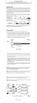
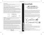
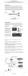
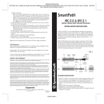
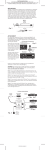
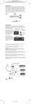
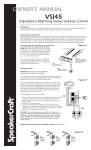
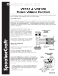
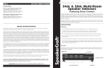
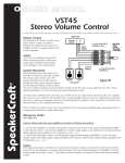
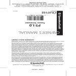
PRINTER’S INSTRUCTIONS:
INSTR,INSTL,IRE-5.0 • LINEAR P/N: 223116X20 • INK: BLACK •
MATERIAL: 20LB. GLOSS WHITE PAPER • SIZE: 4.250” X 17.500” FOLD TO 4.250” X 3.500”
• FOLDING: 5 PARALLEL FAN-FOLDS, FINISH WITH LOGO SHOWING • SCALE: 1-1
DESCRIPTION
The IRE-5.0 IR Blaster is a unique wand-shaped device containing
two very high output IR emitters. The Blaster wand is designed in
such a fashion as to allow the correct overhang (installer adjusted)
for control of a stack of A/V components. It can be mounted above
or below the components, or both, to ensure good coverage. It may
also be located up to 35 feet opposite the controlled equipment for
“across the room” operation, where conditions permit.
The dual emitters operate at different portions of the IR spectrum to
ensure robust operation of the widest range of IR controlled products.
Clear adhesive is used to mount the device, plus a small screw is also
provided to ensure no “drop-off”. The ILC-1.0 IR Collector can be used
to assist the IRE-5.0 Blaster in the control of stacked components,
where necessary. Refer to the ILC-1.0 Instructions.
Fig. 1
3" (76mm)
5/16" (8mm)
Mounting Adhesive
Mounting Screw (included)
Mounting Slot
1/2" (13mm)
White Striped Side is Positive (+)
+
Dual Blaster Diodes
GND
2-Conductor
3.5mm Plug
8' Lead
(2.4m)
ATTACHMENT
1. Arrange the components in the stack so that their front panels are
even, to prevent one shadowing the other. Also, make sure that
the front edges of any shelves are set back far enough to prevent
IR blocking.
2. Before mounting the IRE-5.0 Blaster permanently, hold (or tape
temporarily) in a position where the center of the curved surface
has a 1 to 2 inch overhang above the components (see Fig. 3).
Test and move the Blaster as necessary, until you have operation
of all components.
3. Clean the mounting spot on the cabinet surface of any waxes,
polishes, greasy substances, etc., before permanently mounting
the Blaster.
4. The IRE-5.0 has adhesive tape on its bottom surface. Peel the
protective layer off, exposing the adhesive (see Fig. 2).
Fig. 2
Mounting Screw
(use if needed; see text)
Adhesive
Peel Back Protective
Layer for Mounting
5. Place the IRE-5.0 on the spot determined in step 2 (see Fig. 3).
Press and hold for several seconds to ensure maximum contact of
the adhesive. If the material of the cabinet permits, use the small
screw provided, driving it about midway through the slot in the
wand. (The slot allows room for future adjustment, if needed).
The screw ensures permanency in the event the adhesive does
not adhere well on some surfaces or you do not wish to use the
adhesive at all.
223116X20 • IMAGE 1
PRINTER’S INSTRUCTIONS:
INSTR,INSTL,IRE-5.0 • LINEAR P/N: 223116X20 • INK: BLACK •
MATERIAL: 20LB. GLOSS WHITE PAPER • SIZE: 4.250” X 17.500” FOLD TO 4.250” X 3.500”
• FOLDING: 5 PARALLEL FAN-FOLDS, FINISH WITH LOGO SHOWING • SCALE: 1-1
ELT03500
LIT03500 (rev1)
223116X20
64254 70666
6
SpeakerCraft
0
INSTALLATION INSTRUCTIONS
IR Blaster
IRE-5.0
®
SmartPath™
Fig. 3
Stacked Components in Cabinet
Remote Control
IRE-5.0
IR Blaster
IR Receiver
Shelves
+12V
IR IN
GND
ILC-1.0
IR Light Collector
(use if needed)
STATUS IN
5~24V DC
EMITTERS
IR
RCVR
ST OUT
(use any of the
SpeakerCraft
IR Receivers)
AT-1. 0
AMPLIFIED
TERMINATOR
Cabinet
Door
SpeakerCraft
®
BL ON
BL ON
NET ON
PS-1.0
Power
Supply
To 120V AC
(unswitched)
EMITTERS /
BLASTERS
12V DC
REGULATED
EM ON
EM ON
NET OFF
2nd IRE-5.0 IR Blaster
AT-1.0
(use if needed)
Amplified Terminator
CONNECTIONS
1. Plug the IRE-5.0 Blaster(s) into the EMITTERS/BLASTERS port(s) on
the SpeakerCraft AT-1.0 Amplified Terminator (see Fig. 3).
2. Set the DIP switch(s) on the Terminator to the BL ON (Blaster ON)
position.
CAUTION: The BL ON position sets the AT-1.0 to very high Blaster
Power. Be sure to return the DIP switch(s) to EM ON (Emitter ON)
position when driving normal emitters. Failure to do so will
smoke the emitters!
3. Power the AT-1.0. Assuming other system connections have been
properly made, the components will now respond to Blaster control.
Note 1: Usually only one IRE-5.0 Blaster is necessary to control an
average stack of components. For larger stacks, or if you have a
problem, use a 2nd IRE-5.0 Blaster mounted at the bottom shooting
upward (see Fig. 3). Use the ILC-1.0 IR Light Collectors also,
if necessary.
Note 2: If you are using the IRE-5.0 Blaster in an “across the room”
location, be sure no intervening objects obstruct the IR signal.
Remember, you need a direct “line of sight” path between the Blaster
and the controlled components at all times! Also, do not use the
ILC-1.0 IR Light Collectors for “across the room” operation.
LIMITED 5-YEAR WARRANTY
SpeakerCraft Inc. warrants to the original retail purchaser only that this
SpeakerCraft product will be free from defects in materials and workmanship, for a period of 5-years, provided it was purchased from a SpeakerCraft
Authorized Dealer.
Defective products must be shipped, together with proof of purchase,
prepaid insured to the SpeakerCraft Authorized Dealer from whom they
were purchased, or to the SpeakerCraft factory at the address listed on this
installation instruction manual. Freight collect shipments will be refused. It
is preferable to ship this product in the original shipping container to lessen
the chance of transit damage. In any case, the risk or loss or damage in
transit is to be borne by the purchaser. If upon examination at the Factory
or SpeakerCraft Authorized Dealer it is determined that the unit was defective in materials or workmanship at any time during this warranty period,
SpeakerCraft or the SpeakerCraft Authorized Dealer will, at its option, repair
or replace this product at no additional charge, except as set forth below.
If this model is no longer available and can not be repaired effectively,
SpeakerCraft, at its sole option may replace the unit with a current model
of equal or greater value. In some cases where a new model is substituted,
a modification to the mounting surface may be required. If mounting
surface modification is required, SpeakerCraft assumes no responsibility or
liability for such modification. All replaced parts and product become the
property of SpeakerCraft Inc. Products replaced or repaired under this
warranty will be returned to the original retail purchaser, within a reasonable time, freight prepaid.
This warranty does not include service or parts to repair damage caused
by accident, disaster, misuse, abuse, negligence, inadequate packing or
shipping procedures, commercial use, voltage inputs in excess of the rated
maximum of the unit, or service, repair or modification of the product which
has not been authorized or approved by SpeakerCraft. This warranty also
excludes normal cosmetic deterioration caused by environmental conditions.
This warranty will be void if the Serial number on the product has been
removed, tampered with or defaced.
This warranty is in lieu of all other expressed warranties. If the product is
defective in materials or workmanship as warranted above, the purchaser’s
sole remedy shall be repair or replacement as provided above. In no event
will SpeakerCraft be liable for any incidental or consequential damages
arising out of the use or inability to use the product, even if SpeakerCraft
Inc. or a SpeakerCraft Inc. Authorized Dealer has been advised of the possibility of such damages, or for any claim by any other party. Some states
do not allow the exclusion or limitation of consequential damages, so the
above limitation and exclusion may not apply. All implied warranties on the
product are limited to the duration of this expressed warranty. Some states
do not allow limitation on the length of an implied Warranty. If the original
retail purchaser resides in such a state, this limitation does not apply.
SpeakerCraft
Phone 1-800-448-0976
®
940 Columbia Avenue, Riverside, CA 92507
•
www.speakercraft.com
2
223116X20 • IMAGE 2
•
Fax 951-787-8747