1
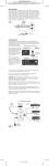
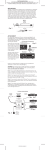
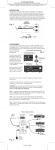
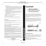
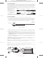
PRINTER’S INSTRUCTIONS:
INSTR,INSTL,IRE-0.5 • LINEAR P/N: 224574X2 • INK: BLACK •
MATERIAL: 20LB. GLOSS WHITE PAPER • SIZE: 4.250” X 14.000” FOLD TO 4.250” X 3.500”
• FOLDING: 4 PARALLEL FAN-FOLDS, FINISH WITH LOGO SHOWING • SCALE: 1-1
DESCRIPTION
The IRE-0.5 is a tiny IR emitter that can be placed on the inside of a component,
near the component’s IR sensor. This approach avoids the untidy appearance
of externally placed front panel emitters and also makes the emitters tamper
and "cleaning person" proof. The IRE-0.5 emitters have very high IR output
which allow them to "blast" around internal chassis surfaces and through
semi opaque materials (such as printed circuit boards) to reach the component’s internal IR sensor.
The IRE-0.5 is equipped with a 3.5mm In-Line jack and includes a model PTP-8
eight foot extension cable (Fig. 1). This allows a quick disconnect so that a
component can be
IRE-0.5
Micro Mini Emitter
moved or removed
White Striped Side
2-Conductor Black
2-Conductor 3.5mm
is Positive (+)
Stranded Mini Wire
Mono In-line Jack
easily without
Emitter
"unthreading" cables,
etc. Three pieces of
24"
(0.6m)
spare adhesives for the
Fig. 1
emitter are also included. PTP-8
8' Extension Cable
+
IRE-0.5
Included Parts
2-Conductor
3.5mm Mini Plug
2-Conductor Black
Stranded Wire, 24 AWG
White Striped Side
is Positive (+)
2-Conductor
3.5mm Mini Plug
8'
(2.4m)
CAUTION: Removing the cover and placing external items within a component may void the manufacturer’s warranty.
ATTACHMENT
1. Remove the component’s cover and locate it’s IR Sensor module.
2. Find a flat surface within the chassis as close as possible to the IR Sensor.
The flat surface should allow, when mounted, the IRE-0.5 dome side (Fig. 2)
to point toward the front of the component’s IR sensor. Now thoroughly
clean the mounting surface of any fingerprints or other greasy substances.
3. The IRE-0.5 has a dark foam adhesive layer on its back surface. Carefully
peel the protective layer off, exposing the adhesive (Fig. 2).
Fig. 2
High Output
(Dome) Side
Micro Mini
Emitter
Mounting Adhesive
Peel Off Protective Layer
Low Output Side
IRE-0.5 Detail
4. Orient the IRE-0.5 as noted above and press it onto the mounting surface.
Press & hold for several seconds to ensure maximum contact of the adhesive.
5. Dress the IRE-0.5 lead so that it does not put strain on the adhesive, other
wise it may "pop off" later.
6. Dress the remainder of the lead around chassis parts and bring the disconnect jack out through a slot or space so that it hangs outside of the rear panel.
CAUTION: Be sure the lead is routed so that it will not come in contact
with any hot surfaces or moving parts! Be sure it is not pinched when
you replace the cover.
7. Plug the PTP-8 extension cable into the disconnect jack and plug the other
end into an EMITTER jack on the AT-1.0 or other SpeakerCraft product. See
Fig. 3 for a typical system.
CAUTION: Do not plug into an emitter jack that is set to Blaster Power (BL
ON) or to the HIGH OUT of other manufacturer’s connecting blocks.
To do so will smoke the emitters!!
Note 1: If you have difficulty finding the component’s IR sensor, try using a
flashlight to first locate it from the front panel. Sometimes the owner’s manual
is helpful. You may need to contact the manufacturer direct.
Note 2: If you need to remove the IRE-0.5 emitter previously stuck to a component’s surface, use a fresh adhesive (included) before reattaching.
Note 3: Use the higher power setting (NOT Blaster Power) on the connecting
block or terminator, if so provided.
PTP-8
Extension
Cable
Remote Control
In-Line
Disconnect
Jack
Controlled Components
IRE-0.5 Micro Mini Emitter
IRC-3.0
Component's
IR Sensor
+12V
GND
STATUS IN
5~24 VDC
EMITTERS
IR
RCVR
ST OUT
IR IN
Shelf Top
IR Receiver
AT-1.0
AMPLIFIED
TERMINATOR
SpeakerCraft
®
Power
Supply
To 120 V AC
(unswitched)
BL ON
BL ON
NET ON
EMITTERS /
BLASTERS
12 VDC
REGULATED
PS-1.0
EM ON
EM ON
NET OFF
AT-1.0
Amplified Terminator
A Typical IRE-0.5 Application
224574X2 • IMAGE 1
Fig. 3
PRINTER’S INSTRUCTIONS:
INSTR,INSTL,IRE-0.5 • LINEAR P/N: 224574X2 • INK: BLACK •
MATERIAL: 20LB. GLOSS WHITE PAPER • SIZE: 4.250” X 14.000” FOLD TO 4.250” X 3.500”
• FOLDING: 4 PARALLEL FAN-FOLDS, FINISH WITH LOGO SHOWING • SCALE: 1-1
ELT03051
LIT03051
224574X2
INSTALLATION INSTRUCTIONS
Micro Mini IR Emitter
IRE-0.5
SmartPath
™
Fig. 4
PTP-8
3.5mm Plug-to-Plug Cable
Fits 3.5mm Mono Mini Phone Jacks - Each End
GND
+
3.5mm Mono
Mini Plug
2-Conductor Black
Stranded Wire, 24 AWG
White Striped Side
is Positive (+)
3.5mm Mono
Mini Plug
GND
+
8'
(2.4m)
The PTP-8 can be used as an extension between components or devices having
a 3.5mm mono mini phone jack at each end.
A typical application is connecting the in-line jack of the IRE-0.5 Micro Mini
Emitter to the emitter output jacks of controllers, IR terminators, connecting
blocks, etc.
LIMITED 5-YEAR WARRANTY
SpeakerCraft Inc. warrants to the original retail purchaser only that
this SpeakerCraft product will be free from defects in materials and
workmanship, for a period of 5-years, provided it was purchased from
a SpeakerCraft Authorized Dealer.
Defective products must be shipped, together with proof of purchase,
prepaid insured to the SpeakerCraft Authorized Dealer from whom they
were purchased, or to the SpeakerCraft factory at the address listed on
this installation instruction manual. Freight collect shipments will be
refused. It is preferable to ship this product in the original shipping
container to lessen the chance of transit damage. In any case, the risk
or loss or damage in transit is to be borne by the purchaser. If upon
examination at the Factory or SpeakerCraft Authorized Dealer it is
determined that the unit was defective in materials or workmanship at
any time during this warranty period, SpeakerCraft or the SpeakerCraft
Authorized Dealer will, at its option, repair or replace this product at no
additional charge, except as set forth below. If this model is no longer
available and can not be repaired effectively, SpeakerCraft, at its sole
option may replace the unit with a current model of equal or greater
value. In some cases where a new model is substituted, a modification
to the mounting surface may be required. If mounting surface
modification is required, SpeakerCraft assumes no responsibility or
liability for such modification. All replaced parts and product become
the property of SpeakerCraft Inc. Products replaced or repaired under
this warranty will be returned to the original retail purchaser, within a
reasonable time, freight prepaid.
This warranty does not include service or parts to repair damage caused
by accident, disaster, misuse, abuse, negligence, inadequate packing
or shipping procedures, commercial use, voltage inputs in excess of
the rated maximum of the unit, or service, repair or modification of the
product which has not been authorized or approved by SpeakerCraft.
This warranty also excludes normal cosmetic deterioration caused by
environmental conditions. This warranty will be void if the Serial number
on the product has been removed, tampered with or defaced.
This warranty is in lieu of all other expressed warranties. If the product
is defective in materials or workmanship as warranted above, the
purchaser’s sole remedy shall be repair or replacement as provided
above. In no event will SpeakerCraft be liable for any incidental or
consequential damages arising out of the use or inability to use the
product, even if SpeakerCraft Inc. or a SpeakerCraft Inc. Authorized
Dealer has been advised of the possibility of such damages, or for any
claim by any other party. Some states do not allow the exclusion or
limitation of consequential damages, so the above limitation and
exclusion may not apply. All implied warranties on the product are
limited to the duration of this expressed warranty. Some states do not
allow limitation on the length of an implied Warranty. If the original
retail purchaser resides in such a state, this limitation does not apply.
940 Columbia Avenue, Riverside, CA 92507 • 1-800-448-0976 • Fax 951-787-8747
www.speakercraft.com
2
224574X2 • IMAGE 2