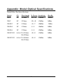
1
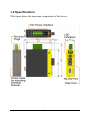
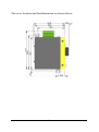
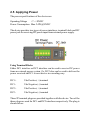
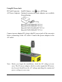
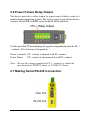
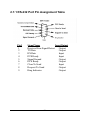
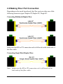
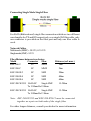
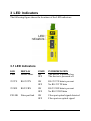
Industrial
Serial RS-232 to Fiber Converter
KSC-200 Series
Installation Guide
DOC.111209-KSC-200
-1-
(C) 2006 KTI Networks Inc. All rights reserved. No part of this documentation may be reproduced in any form or by any means or used to make
any directive work (such as translation or transformation) without permission from KTI Networks Inc.
KTI Networks Inc. reserves the right to revise this documentation and to
make changes in content from time to time without obligation on the part
of KTI Networks Inc. to provide notification of such revision or change.
For more information, contact:
United States
International
KTI Networks Inc.
P.O. BOX 631008
Houston, Texas 77263-1008
Phone:
Fax:
E-mail:
URL:
713-2663891
713-2663893
[email protected]
http://www.ktinet.com/
Fax:
E-mail:
URL:
886-2-26983873
[email protected]
http://www.ktinet.com.tw/
-2-
The information contained in this document is subject to change without
prior notice. Copyright (C) All Rights Reserved.
TRADEMARKS
Ethernet is a registered trademark of Xerox Corp.
FCC NOTICE
This device complies with Class B Part 15 the FCC Rules. Operation is
subject to the following two conditions: (1) This device may not cause
harmful interference, and (2) this device must accept any interference
received including the interference that may cause.
CE NOTICE
Marking by the symbol
indicates compliance of this equipment to
the EMC directive of the European Community. Such marking is indicative that this equipment meets or exceeds the following technical standards:
EMC Class B
EN55022:1998/A1:2000/A2:2003 Class B
EN61000-3-2:2000
EN61000-3-3:1995/A1:2001
EN 55024:1998/A1:2001/A2:2003
IEC 61000-4-2:2001
IEC 61000-4-3:2002/A1:2002
IEC 61000-4-4:1995/A1:2000/A2:2001
IEC 61000-4-5:2001
IEC 61000-4-6:2003
IEC 61000-4-8:2001
IEC 61000-4-11:2001
-3-
Table of Contents
1. Introduction ......................................................... 5
1.1 Features ........................................................................................ 6
1.2 Specifications ................................................................................ 7
2. Installation ......................................................... 11
2.1 Unpacking ..................................................................................... 11
2.2 Safety Cautions .......................................................................... 12
2.3 DIN-Rail Mounting ....................................................................... 13
2.4 Panel Mounting ............................................................................ 15
2.5 Applying Power ........................................................................... 17
2.6 Power Failure Relay Output ........................................................ 20
2.7 Making Serial RS-232 Connection .............................................. 20
2.7.1 RS-232 Port Pin Assignment Table ......................................... 21
2.7.2 Cable for Connection to PC COM Port ..................................... 22
2.8 Making Fiber Port Connection ..................................................... 23
2.9 Application ................................................................................... 25
3 LED Indicators ................................................... 26
3.1 LED Indicators ............................................................................. 26
Appendix: Model Optical Specifications ............ 27
-4-
1. Introduction
The converter is designed to provide the most versatile connection possible between two RS-232 serial equipment using fiber optic cable. It
allows any two pieces of serial equipment to communicate full-duplex
over typical duplex fibers,or over optional single fiber up to 20km. The
converter supports transparent conversion for not only RS-232 data lines,
but also all RS-232 control signals. It also supports all RS-232 baud rates
with no need for user configuration. The Din-rail mountable design makes
it ideal for industrial cabinets and enclosures.
For industrial environment, the converters are designed with the following enhanced features exceeding that of commercial media converters:
• High and wide operating Temperature
• Wide operating voltage range for DC power input
• Power input interface: Industrial screw terminal block and DC
power jack for external commercial power adapter as option
• DIN rail mounting support for industrial enclosure
• Screw panel mounting support for industrial enclosure
• Industrial-rated Emission and Immunity performance
-5-
1.1 Features
z Transparent conversion for all RS-232 signals
z Supports RS-232 baud rate higher than 115.2K bps
z Auto adaptation and conversion to any RS-232 baud received
z Operation with no required configuration
z Extending all RS-232 signals over long optical cables
z Supports versatile optical cables:
-ST/SC multimode duplex fibers
-SC single mode duplex fibers
-SC single mode single fiber
z Provides surge protection (transient voltage)on RS-232 signals
z Provides high ESD protection on RS-232 signals
z Provides optical isolation between RS-232 and main circuitry
z Low power consumption
z Two power interface type: screw terminal block and DC jack
z Wide operating voltage input range
z Support DIN rail mounting
z Support panel mounting
z High and wide operating temperature range
z Industrial-rated Emission and Immunity performance
-6-
1.2 Specifications
This figure shows the important components of the device:
-7-
Serial Interface (RS-232 Port)
Connector
DB9 female
Pin Assignments
DCE type
Isolation
RS-232 I/O and internal system
Baud Rate Support
Auto-detect, Up to 120K
Connector Shield
Connect to chassis ground
Connection Distance
15 meters
High ESD Tolerance
+/-15KV on Tx, Rx lines
Overvoltage Protection Cutoff if over +/-25V
Isolation
Optical isolation from internal system
Fiber Optic Interface (Fiber Port)
Connector
Duplex ST, Duplex SC, or Bi-Di SC
Data Speed
100Mbps
Duplex Mode
Full duplex
Cable Types
MMF - 50/125, 62.5/125
SMF - 9/125
Link Distance
MMF up to 2 km
SMF -model dependent
Eye Safety compliance IEC825 Class 1
Refer to Appendix for detailed optical specifications.
LED Indicators
LED
DISPLAY
PWR
Power status
TX
RX
FX LNK
RS-232 Tx
RS-232 Rx
Optical status
STATE
ON
OFF
BLINK
BLINK
ON
OFF
-8-
INTERPRETATION
Power on
Power off
RS-232 Tx Activity status
RS-232 Rx Activity status
Fiber port optical signal detected
Fiber port no optical signal
DC Power Interface
Interface
Operating Input Voltages
Power consumption
Screw-type terminal block
1. Two pairs for power wire cascading
2. One pair for power failure relay output
DC Jack (-6.3mm/+D2.0mm)
+7V ~ +30V(+5%)
2.1W @+7.5VDC input
2.14W @+12.6VDC input
2.4W @+30VDC input
Basic Information
Conversion
Transparent for all RS-232 signals
Mechanical
Dimension (base)
Housing
Mounting Support
Weight
W 28mm x D 82mm x H 95mm
Enclosed metal with no fan
DIN-rail mounting, Panel mounting
248g
Environmental
Operating Temperature
Storage Temperature
Relative Humidity
Typical -30oC ~ 70oC (model dependent)
-30oC ~ 85oC
5% ~ 90%
-9-
Certificate
FCC
CE/EMC
CE/LVD Safety
Part 15 Class B
EMI EN50081-1 Class B
EMS EN55024
EN 60950
EN55022
EN61000-3-2
EN61000-3-3
EN 55024
IEC 61000-4-2
IEC 61000-4-3
IEC 61000-4-4
IEC 61000-4-5
IEC 61000-4-6
IEC 61000-4-8
IEC 61000-4-11
ESD Test
RS Test
EFT/BURST Test
Surge Test
CS Test
Magnetic Field
Volatge Int. Dips
-10-
2. Installation
2.1 Unpacking
Check that the following components have been included:
• Information CD
• The device unit
• DIN-rail mounting bracket
If any item is found missing or damaged, please contact your local reseller
for replacement.
The following are available optional accessories:
• Panel Mounting Bracket
The bracket is used for mounting the device on a panel surface.
• Commercial-rated AC power adapters:
- Rated AC120V/60Hz DC7.5V 1A
- Rated AC230V/50Hz DC7.5V 1A
- Rated AC100V/50-60Hz DC7.5V 1A
- Rated AC240V/50Hz DC7.5V 1A
The adapters are used for supplying DC power to the converter
via DC power jack interface.
-11-
2.2 Safety Cautions
To reduce the risk of bodily injury, electrical shock, fire, and damage to
the equipment, observe the following precautions.
• Do not service any product except as explained in your system
documentation.
• Opening or removing covers may expose you to electrical shock.
Only a trained service technician should service components inside
these compartments.
• If any of the following conditions occur, unplug the product from the
electrical outlet and replace the part or contact your trained service
provider:
- The power cable, extension cable, or plug is damaged.
- An object has fallen into the product.
- The product has been exposed to water.
- The product has been dropped or damaged.
- The product does not operate correctly when you follow the
operating instructions.
• Do not push any objects into the openings of your system. Doing
so can cause fire or electric shock by shorting out interior components.
• Operate the product only from the type of external power source
indicated on the electrical ratings label. If you are not sure of the
type of power source required, consult your service provider or local
power company.
-12-
2.3 DIN-Rail Mounting
In the product package, a DIN-rail bracket is installed on the device for
mounting the converter in a industrial DIN-rail enclosure.
The steps to mount the device onto a DIN rail are:
1. Install the mounting bracket onto the device unit as shown below:
2. Attach bracket to the lower edge of the DIN rail and push the unit
upward a little bit until the bracket can clamp on the upper edge of
the DIN rail.
3. Clamp the unit to the DIN rail and make sure it is mounted securely.
4. Make sure that there are proper heat dissipation from and adequate
ventilation around the device.
-13-
The final mechanical dimensions after installing DIN rail mounting bracket
are:
-14-
2.4 Panel Mounting
The device is provided with an optional panel mounting bracket. The
bracket support mounting the device on a plane surface securely. The
mounting steps are:
1. Install the mounting bracket on the device unit.
2. Screw the bracket on the device unit.
3. Screw the device unit on a panel.
4. Make sure that there are proper heat dissipation from and adequate
ventilation around the device. Do not place heavy objects on the
device.
-15-
The screw locations and final dimension are shown below:
-16-
2.5 Applying Power
The power specifications of the device are:
Operating Voltage
+7 ~ +30VDC
Power Consumption Max. 2.4W @30VDC
The device provides two types of power interfaces, terminal block and DC
power jack for receiving DC power input from external power supply.
Using Terminal Blocks
Either DC1 interface or DC2 interface can be used to receive DC power
from an external power system. Or, DC2 also can be used to deliver the
power received on DC1 to next device in cascading way.
DC1 +
Vdc Positive (+) terminal
DC1 -
Vdc Negative (-) terminal
DC2 +
Vdc Positive (+) terminal
DC2 -
Vdc Negative (-) terminal
Three 2P terminal plugs are provided together with the device. Two of the
three plugs are used for DC1 and DC2 interfaces respectively. The plug is
shown below:
-17-
Power wires: 24 ~ 12AWG (IEC 0.5~2.5mm2)
Install the power source wires with the plug properly. Screw the wire with
plug securely. Then, plug in DC1 contacts.
If cascading the power to next device is needed, install the power wires
and plug for another switch. Then, use DC2 contacts.
Note: Only up to four device units can be cascaded to receive power
from one main power input source.
-18-
Using DC Power Jack
DC Jack Connector: Jack D 6.3mm
D 2.0mm
AC Power Adapters: Optional commercial rated adapters are available
for purchasing.
Rated AC120V/60Hz DC7.5V 1A
Rated AC230V/50Hz DC7.5V 1A
Rated AC100V/50-60Hz DC7.5V 1A
Rated AC240V/50Hz DC7.5V 1A
Connect power adapter DC plug to the DC power jack of the converter
before connecting to the AC outlet. Connect the power adapter to the
AC outlet.
Note: Before you begin the installation, check the AC voltage of your
area. The AC power adapter which is used to supply the DC power
for the unit should have the AC voltage matching the commercial
power voltage in your area.
-19-
2.6 Power Failure Relay Output
The device provides a relay output to report power failure event to a
remote alarm monitoring system. The replay output is provided with two
contacts labeled PF+ and PF- in the terminal block interface.
Use the provided 2P terminal plug for signal wiring and plug into the PF+/
- contacts. The function is designed as :
Power is normal PF+ contact is shorted with PF- contact.
Power failure
PF+ contact is disconnected with PF- contact.
Note: Be sure the voltage applied on PF+/- contacts is within the
specification of 30VDC/1A max. or 120VAC/0.5A max.
2.7 Making Serial RS-232 Connection
-20-
2.7.1 RS-232 Port Pin Assignment Table
Pin#
1
2
3
4
5
6
7
8
9
Signal Name
Input/Output
Received Line Signal Detect
Output
TX Data
Output
RX Data
Input
DTE Ready
Input
Signal Ground
Output
DCE Ready
Output
Clear To Send
Input
Request To Send
Output
Ring Indicator
Output
-21-
2.7.2 Cable for Connection to PC COM Port
Connecting to 9-pin DTE device (Computer or PC COM)
Connecting to 25-pin DTE device (Computer or PC COM)
-22-
2.8 Making Fiber Port Connection
Depending on the model purchased, the fiber port provides one of the
following connector types: Duplex ST, Duplex SC, Single SC.
Connecting Multimode Duplex Fiber
Make sure the RX-to-TX connection rule is followed on the both ends of
the fiber cable.
Connecting Single Mode Duplex Fiber
Note: Make sure the RX-to-TX connection rule is followed on the
both ends of the fiber cable.
-23-
Connecting Single Mode Single Fiber
For Bi-Di (Bidirectional) single fiber connection which use two different
wavelengths for TX and RX respectively over single SM fiber cable, only
one connector is provided on the fiber port and only one fiber cable is
used.
Network Cables
Multimode (MMF) - 50/125, 62.5/125
Single mode (SMF) - 9/125
Fiber Distance between two devices
Model
Connector Fiber
KSC-200-T
ST
MMF
Distance (ref. max.)
2km
KSC-200-C
SC
MMF
2km
KSC-200-SL2
SC
SMF
20km
KSC-200-SL4
SC
SMF
40km
KSC-200-SL6
SC
SMF
60km
KSC-200-W3515 Bi-Di SC
Single SMF
Tx 1310nm Rx 1550nm
15~20km
KSC-200-W5315 Bi-Di SC
Single SMF
Tx 1550nm Rx 1310nm
15~20km
Note: KSC-200-W3515 and KSC-200-W5315 must be connected
together as a pair on both ends of the single fiber.
For other longer distances, consult your dealer for more information.
-24-
2.9 Application
The converter can be used to extend the distance between two serial
devices via fiber cables. The distance can be 2km, 20km, and even up to
100km.
The following example illustrates a PC performs serial communocation
with another RS-232 device far apart:
The converter converts all signals of the COM port of the PC to optical
signals and sends to the other converter far apart over fiber cable.
-25-
3 LED Indicators
The following figure shows the locations of the LED indicators:
3.1 LED Indicators
LED
PWR
DISPLAY
Power status
STATE
ON
OFF
INTERPRETATION
The device is powered on.
The device is powered off.
232 TX
RS-232 TX
ON
OFF
RS-232 TX data is present
No RS-232 TX data
232 RX
RS-232 RX
ON
OFF
RS-232 RX data is present
No RS-232 RX data
FX LNK
Fiber port link
ON
OFF
Fiber port optical signal detected
Fiber port no optical signal
-26-
Appendix: Model Optical Specifications
Model Fiber Port Specifications
Model
FX
Wavelength
Tx Power Sensitivity
Max.Rx
200-T
ST
1310nm
-20~-14
-32dBm
-8dBm
200-C
SC
1310nm
-20~-14
-31dBm
0dBm
200-SL2
SC
1310nm
-15~-7
-30dBm
-7dBm
200-SL4
SC
1310nm
-5~ 0
-34dBm
0dBm
200-SL6
SC
1310nm
-5~ 0
-35dBm
0dBm
200-W3515
BiDi SC Tx 1310nm
-14~-8
-31dBm
0dBm
-14~-8
-31dBm
0dBm
Rx 1550nm
200-W5315
BiDi SC Tx 1550nm
Rx 1310nm
-27-