1
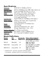
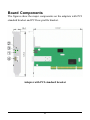
Installation Guide
1000Base-X Gigabit Ethernet
PCI Adapter with SFP Support
KG-500F series
DOC.070607-KG-500F-K
1
The information contained in this document is subject to change
without prior notice. Copyright (C) All Rights Reserved.
TRADEMARKS
All brand names are trademarks or registered trademarks of their
respective holders.
Warning
This equipment has been tested and found to comply with the limits
for Class B digital device, pursuant to Part 15 of the FCC Rules.
These limits are designed to provide reasonable protection against
harmful interference when the equipment is operated in a residential
installation. This equipment generates, uses, and can radiate radio
frequency energy and if not installed and used in accordance with the
instruction manual may cause harmful interference to radio communications. However, there is no guarantee that interference will not
occur in a particular installation. If this equipment does cause harmful interference to radio or television reception, which can be determined by turning the equipment off and on, the user is encouraged to
try to correct the interference by one or more of the following
measures:
• Reorient or relocate the receiving antenna.
• Increase the separation between the equipment and receiver.
• Connect the equipment into an outlet on a circuit different
from that to which the receiver is connected.
Consult the dealer or an experienced radio TV technician for help.
Notice: The changes or modifications not expressly approved by
the party responsible for compliance could void the user authority
to operate the equipment.
2
CISPR 22 Class B
This device complies with EMC directive of the European Community and meets or exceeds the following technical standard: EN 55022
- Limits and Methods of Measurement of Radio Interference Characteristics of Information Technology Equipment. This device complies with CISPR 22 Class B.
CE NOTICE
Marking by the symbol
indicates compliance of this equipment to the EMC directive of the European Community. Such marking
is indicative that this equipment meets or exceeds the following
technical standards:
EN55022/CISPR 22 ClassB
EN55024 - EN61000-3-2, EN61000-3-3, EN61000-4 series
3
Introduction
The 1000BASE-X Gigabit Ethernet PCI Adapter is a 32-bit LAN
adapter for use in personal computers with PCI computer bus slots.
This adapter features a mini-GBIC fiber connector (SFP) for a 1000
Mbps IEEE 802.3z Ethernet network connection over optical fiber
cable. The series provides different fiber transceiver types supporting short, middle, and long reach applications.
Adapter Features
Supports 32-bit 33/66MHz PCI of Rev.2.1/2.2/2.3 specifica-
tion
IEEE 802.3z 1000Base-SX/LX compliant
Provides Tx 8K / Rx 64KB RAM buffer
Supports full duplex operation up to 2000Mbps data rate over
fiber
Supports full duplex flow control
Plug-and-Play installation
Provides LED indicators for easy diagnostic
Provides SFP to support variety of fiber transceivers
Complete driver support for most operating systems
Supports 802.1Q VLAN tagging
Supports drivers for Windows XP/2K/2K3/VistaX32/
VistaX64/Linux/NetWare systems and plug-and-play installation for Widnows 2K3.
4
Specifications
Standards
Network Port
Host Interface
LEDs
Network Cables
IEEE 802.3z 1000Base-SX/LX
SFP for 1000Mbps mini-GBIC fiber transceiver
32-bit 33/66Mhz PCI Rev.2.1/2.2/2.3
SFP status, Link status, Optical status
50/125 multimode fiber up to 500m
62.5/125 multimode fiber up to 220m
9/125 single mode fiber
Transfer Rate
Gigabit Ethernet: 2000Mbps (Full-duplex)
Driver Support Windows XP, 2000, 2003, VistaX32/64,
Linux, Netware server
Power
Consumption PCI 3.3V/400mA max.
Dimension
130 x 65 mm
Environment
Operation Temperature: 0oC ~50oC
Storage Temperature: -20oC ~85oC
Relative Humidity 5%~95%non-condensing
Laser Eye Safe
IEC 60825-1 Class 1/CDRH Class I
Approval
FCC Class B,CE CISPR22 Class B
Model Definitions
Model
500-SX
500-LX
500/LP-SX
500/LP-LX
PCI
Standard
Connector Fiber Cable Support
LC
62.5/125 MMF up to 200m
50/125 MMF up to 500m
Standard
LC
MMF up to 550m
SMF up to 10km
Low-profile LC
62.5/125 MMF up to 200m
50/125 MMF up to 500m
Low-profile LC
MMF up to 550m
SMF up to 10km
* Standard PCI: mounted with PCI standard bracket
Low-profile: mounted with PCI low-profile bracket
5
Board Components
The figures show the major components on the adapters with PCI
standard bracket and PCI low-profile bracket.
Adapter with PCI standard bracket
6
Adapter with PCI low-profile bracket
No. Components
Description
1
LINK LED
This LED lights when the
fiber connection is established.
2
SFP LED
This LED lights when a mini-GBIC
transceiver module is installed in
the SFP slot.
3
OL LED
This LED lights when optical signal
is presented in the transceiver.
4
SFP Slot
This slot supports mounting a
mini-GBIC fiber transceiver.
7
Installing the Adapter
Before installing the adapter, you need the following:
• A computer system that is compliant with the PCI specifications version 2.1 or later.
• An available PCI bus master slot in the computer
• The adapter driver diskettes (or CD supplied with the adapter)
• Fiber cables
Inserting the Adapter into the PCI Slot
To install the adapter in your computer, follow these steps:
1. Turn off the power to the computer.
2. Remove the computer's cover.
3. Unscrew and remove the slot cover from the PCI bus slot.
4. Insert the adapter into the slot and secure the screw.
5. Replace the computer cover and reconnect all previously
connected cables.
8
Installing Mini-GBIC Transceiver
A typical mini-GBIC SFP transceiver is shown as follows:
To install a fiber transceiver into the SFP slot, the steps are:
1. Insert the fiber transceiver into the mini-GBIC SFP port.
Normally, a bail is provided for every SFP transceiver. Hold the
bail and make insertion.
2. Until the fiber transceiver is seated securely in the slot, place
the bail in lock position.
The mini-GBIC SFP slot supports hot-plug installation even when
the computer is powered and operating.
9
Connecting to the Network
The rear bracket of the PCI adapter contains two fiber connectors.
The TX connector is used for transmission and the RX is used for
reception. When connecting to a device using fiber cable, make sure
the TX connector of the adapter is connected to the RX connector
of the device and RX connector is connected to the TX connector of
the device.
In order to have a reliable communication between two ends, the
speed and duplex configuration of the adapter's fiber port and the
device at the remote end must be same. Configure the driver of the
adapter as follows: Auto, 1000Mbps, Full-duplex.
10
Network Driver Installation
After making the connection to the network, you must install the
adapter network driver in order to connect the network adapter to
your network operating system.
The adapter driver media contain the latest versions of the network
drivers available when the adapter is shipped from the factory. A
file, \README.TXT, located in the diskette's root directory contains a list of the supported driver software and the directory structures for the supported operating environments. Please refer to this
file first before installing any network driver for the adapter.
Installation for Windows Systems
For adapter installation on Windows 2003 (Win2K3), the system
will detect and configure the drivers for the adapter automatically
with no need for extra driver setup. The adapter is detected as :
Win2k3
Realtek RTL8169/8110 Family Gigabit Ethernet NIC
Using the Associated Drivers in the driver diskette
After driver setup, the adapter is identified as :
Realtek RTL8169/8110 Family Gigabit Ethernet NIC
Link Speed/Duplex Mode options : Auto-negotiation
Installation for other Systems
Refer to \README.TXT first in the driver CD for the driver installation on other operating systems. The file contains driver information for most of the popular operating systems.
11
LED Indicators
The adapter has three LEDs. The interpretations of the LEDs are:
LINK LED indicates an active 1000Mbps connection is established.
On : Good link between the adapter and a remote device
Off : No connection between adapter and a remote device
Blink: Link on and traffic activities
SFP LED indicates installation status of mini-GBIC transceiver
On :
Off :
A mini-GBIC SFP transceiver is installed in the SFP slot.
No transceiver is installed.
OL LED indicates optical signal status
On :
Off :
Optical signal is detected.
No optical signal is detected.
If you experience any problems, first make sure that the appropriate driver is loaded, the proper cable is connected to the connector,
and the connected device complies with 1000BASE-X standard.
Then recheck the LED.
12