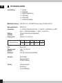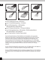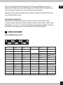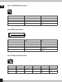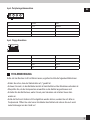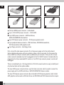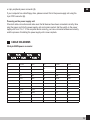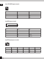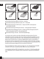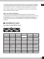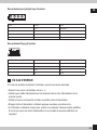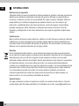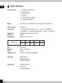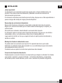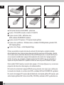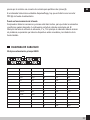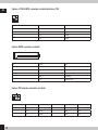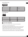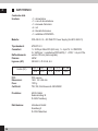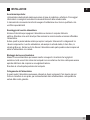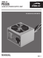
1
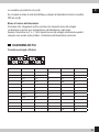
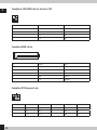
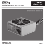
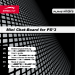
PECOS
420W ATX POWER SUPPLY UNIT
CP4-420-V.2.0 (SL-6910-SSV-01)
Manual
Vers. 1.1
INFORMATIONEN
DE
Haftungsausschluss
Die Jöllenbeck GmbH übernimmt keine Haftung für Schäden am Produkt oder Verletzungen von
Personen aufgrund von unachtsamer, unsachgemäßer, falscher oder dem Herstellerzweck
nicht entsprechender Verwendung des Produkts. Unter keinen Umständen haftet die Jöllenbeck
GmbH für tatsächlich entstandene, mittelbare, unmittelbare oder Folgeschäden, Datenverlust, Produktionsausfälle, Einkommensausfall oder entgangenen Gewinn, Sachschäden und
Ersatzansprüche Dritter. Sie sollten vor dem Formatieren und Partitionieren der Festplatte eine
vollständige Sicherheitskopie Ihres Systems erstellen.
Störungen
Unter Einwirkung von starken statischen, elektrischen oder hochfrequenten Feldern (Funkanlagen, Mobiltelefonen, Mikrowellen-Entladungen) kann es zu Funktionsbeeinträchtigungen des
Gerätes (der Geräte) kommen. Versuchen Sie in diesem Fall, die Distanz zu den störenden
Geräten zu vergrößern.
Entsorgung
Die Kennzeichnung auf dem Produkt bzw. in der dazugehörigen Literatur gibt an, dass es
nach seiner Lebensdauer nicht zusammen mit dem normalen Haushaltsmüll entsorgt werden
darf. Entsorgen Sie dieses Gerät bitte getrennt von anderen Abfällen, um der Umwelt bzw.
der menschlichen Gesundheit nicht durch unkontrollierte Müllbeseitigung zu schaden. Recyceln
Sie das Gerät, um die nachhaltige Wiederverwertung von stofflichen Ressourcen zu fördern.
Private Nutzer sollten den Händler, bei dem das Produkt gekauft wurde, oder die zuständigen
Behörden kontaktieren, um in Erfahrung zu bringen, wie sie das Gerät auf umweltfreundliche
Weise recyceln können. Gewerbliche Nutzer sollten sich an Ihren Lieferanten wenden und die
Bedingungen des Verkaufsvertrags konsultieren. Dieses Produkt darf nicht zusammen mit
anderem Gewerbemüll entsorgt werden.
Technischer Support
Bei Fragen oder Problemen steht Ihnen unser technischer Support zur Verfügung.
Schauen Sie auf die Webseite http://www.speedlink.com oder schreiben Sie eine E-Mail an:
[email protected]
2
WICHTIGE SICHERHEITSHINWEISE
DE
Stromversorgung
Überprüfen Sie vor dem Anschließen die Versorgungsspannung. Die Stromquelle, mit der das
Netzteil betrieben wird, muss den auf dem Etikett angegebenen Werten entsprechen. Benutzen
Sie das Netzteil nie für Geräte, deren Spannung größer ist als die für das Netzteil vorgesehene,
Sie laufen Gefahr, Netzteil und Gerät zu beschädigen.
Für den Betrieb dieses Geräts sollte sich die Steckdose in der Nähe befinden und leicht
zugänglich sein.
Dieses Gerät ist erst vollständig vom Strom getrennt, wenn der Netzstecker gezogen ist.
Reinigung
Schalten Sie das Netzteil vor dem Reinigen bitte aus und trennen Sie es vom Stromnetz. Reinigen Sie das Gerät bitte nur von außen und verwenden Sie dazu ein weiches, trockenes Tuch.
Fehlerbeseitigung/Reparatur
Um der Gefahr eines Stromschlages vorzubeugen, öffnen Sie das Netzteilgehäuse nicht. Dieses
Produkt enthält keine austauschbaren Teile. Versuchen Sie nicht, das Gerät selbst zu warten
oder zu reparieren. Überlassen Sie jegliche Reparatur dem zuständigen Fachpersonal. Nehmen
Sie keine Veränderungen am Gerät vor. Dadurch verlieren Sie jegliche Garantieansprüche.
Feuchtigkeit/Wärmequellen
Verwenden Sie das Gerät nicht in der Nähe von Wasser (z. B. Waschbecken, Badewannen etc.),
und halten Sie es von Feuchtigkeit, tropfenden oder spritzenden Flüssigkeiten sowie Regen
fern. Setzen Sie das Gerät keinen hohen Temperaturen, hoher Luftfeuchtigkeit oder direktem
Sonnenlicht aus.
3
TECHNISCHE DATEN
DE
Lieferumfang: • 1 × Netzteil
• 1 × Netzkabel
• 1 × Bedienungsanleitung
• 4 × Schrauben
• 4 × Kabelbinder
• 1 × PATA/SATA-Adapter
Modellbeschreibung: CP4-420-V.2.0 – 420 Watt PC Power Supply (SL-6910-SSV-01)
Bauform/Standard: ATX/ATX 2.3
Anschlüsse:
1 × 20/24-pin Main ATX (420 mm), 1 × 4-pin P4, 3 × IDE/PATA, 2 × SATA
(plus 1 × PATA/SATA-Adapter), 1 × FDD, 1 × 6-pin PCIe
Kühlung: 120-mm-Lüfter (temperaturgesteuert)
Leistung:
420 W
Eingang (DC):
200-240 V, 47-53 Hz, 6 A
Ausgangsleistung
4
+3,3 V
24 A
+5 V
21 A
+12 V
31 A
-12V
0,3 A
PFC:
Abmessungen:
Gewicht:
Zertifikate:
Passiv-PFC
148 × 140 × 86 mm
1270 g
TÜV, CE, RoHS nach 2002/95/EC
Hersteller:
ACOS GmbH
Kulemannstieg 34
D-22457 Hamburg
Vertrieb: Jöllenbeck GmbH
Kreuzberg 2
D-27404 Weertzen
5 V SB
2,5 A
INSTALLATION
DE
Wichtiger Hinweis:
Die Stromversorgung des Mainboards kann abhängig von Hersteller und Produkt variieren.
Bitte greifen Sie für detaillierte Angaben und Anweisungen auf die Bedienungsanweisung Ihres
Mainboards zurück.
Sollten Sie keine Fachkenntnisse für den Einbau besitzen, so lassen Sie ihn bitte von einer
Fachkraft oder einer entsprechenden Fachwerkstatt vornehmen!
Ausbau des alten Netzteils
Schalten Sie Ihr Netzteil am Netzschalter aus und trennen Sie den Rechner vom Stromnetz.
Warten Sie ungefähr zwanzig Minuten, damit sich der Reststrom entladen und das Netzteil
abkühlen kann. Dann öffnen Sie den Computer, indem Sie die linke Seitenwand abschrauben.
Als nächstes trennen Sie alle Verbindungen vom alten Netzteil zu den verschiedenen
Komponenten wie z.B. dem Motherboard, der Festplatte, der Grafikarte etc. Danach lösen Sie die
Schrauben, mit denen das Netzteil an der Rückseite des Rechners befestigt ist, und nehmen
es vorsichtig heraus.
Einbau des neuen Netzteils
Nun können Sie das neue Netzteil in die Halterung schieben. Achten Sie dabei darauf, dass das
eine Lüftungsgitter zur Rechnerinnenseite nicht versperrt ist und die heiße Luft aus dem Computerinnenraum angesaugt und nach außen weggeleitet werden kann.
Dann ziehen Sie die Schrauben an der Rückseite des Rechners wieder fest.
Anschluss des Netzteils
Nun können Sie damit beginnen, das Netzteil an die Komponenten anzuschließen. Bitte
versuchen Sie nie mit Gewalt einen Stecker mit einem Anschluss zu verbinden.
Netzteil und Hardware-Komponenten tragen dadurch Schäden davon, die nicht unter unsere
Garantieleistung fallen.
5
DE
1
2
3
4
5
6
20+4-pol. MAIN-Stromanschluss – Motherboard
4-pol. +12V-AUX/P4-Stromanschluss – 12V-AUX/P4
3 5-pol. S-ATA-Stromanschluss – SATA-Festplatten,
SATA-CD-ROM-/DVD-Laufwerke/Brenner
4 6-pol. PCI Express-Stromanschluss – PCI Express Grafikkarten
5 4-pol. Peripheriegeräteanschluss – IDE-Festplatten, CD-ROM-Laufwerke/Brenner, DVD-Laufwerke/Brenner, AGP-Grafikkarten
6 4-pol. Floppy-Anschluss – Disketten-/Floppy-Laufwerk
1
2
Zuerst wird Hauptstromstecker (1) des Netzteils an der Hauptplatine, dem sogenannten
Motherboard angeschlossen. Einige Motherboards benötigen dazu einen 20-pol.-Anschluss,
andere einen 24-pol.-Anschluss. Für diesen Fall verfügt das Pecos 420 Watt über einen
20-pol.-Anschluss mit 4-Pol-Zusatzstecker. Diese 4-pol.-Erweiterung von 20- auf 24-poligen
Kombistecker darf nicht in die weit entlegene 12V-AUX/P4-Buchse gesteckt werden. Sie gehört
entweder in die 24-polige Extended ATX Buchse oder bleibt im Falle von ATX 20-polig
ungenutzt.
Für den 12V-AUX-Anschluss gibt es einen eigenen 4-pol.-+12V-Stecker (2), der z.B. dadurch zu
erkennen ist, dass er nur über zwei schwarze und zwei gelbe Kabel verfügt.
Der 5-pol. SATA-Stromanschluss (3) ist ein sehr flacher, schwarzer Stecker, der der Verbindung
des Netzteils mit einer SATA-Festplatte oder SATA-CD-ROM-/DVD-Laufwerken oder -Brennern
dient.
6
Der 6-pol. PCI Express-Stromanschluss (4) ist für PCI Express Grafikkarten vorgesehen,
bestimmte AGP-Grafikkarten sowie IDE-Festplatten und CD-ROM-und DVD-Laufwerke sowie
-Brenner benötigen hingegen einen 4-pol. Peripherie-Stromanschluss (5).
DE
Verfügt Ihr Rechner über ein Disketten-/Floppy-Laufwerk, verbinden Sie dieses bitte über den
4-pol.-FDD (6) mit dem Netzteil.
Inbetriebnahme des Netzteils
Überprüfen Sie alle Kabelverbindungen und stellen Sie sicher, dass alle Geräte richtig
verbunden wurden. Stecken Sie dann das Netzkabel in Netzteil und Steckdose. Legen Sie den
Netzschalter von „0“ auf „I“ um. Lässt sich der Rechner nun problemlos hochfahren, haben Sie
alle Geräte korrekt angeschlossen und die Installation des Netzteils ist beendet.
KABELDIAGRAMME
20+4 pol. MAIN-Stromanschluss
13
24
1
12
Pol
Funktion
Farbe
1
+3,3 V
Orange
2
+3,3 V
Orange
3
COM
Schwarz
4
+5 V
5
Pol
Funktion
Farbe
+3,3 V
Orange
+3,3 Vs
Braun
14
-12 V
Blau
Rot
15
COM
Schwarz
COM
Schwarz
16
PS-ON
Grün
6
+5 V
Rot
17
COM
Schwarz
7
COM
Grau
18
COM
Schwarz
8
PWR OK
Blau
19
COM
Schwarz
9
+5 VSB
Gelb
20
---
---
10
+12 V
Gelb
21
+5 V
Rot
11
+12 V
Orange
22
+5 V
Rot
12
+3 V
23
+5 V
Rot
24
COM
Schwarz
13
7
4-pol. +12V-AUX/P4-Stromanschluss
DE
3
1
Pol
Funktion
Farbe
1
COM
Schwarz
2
COM
Schwarz
3
+12 V
Gelb
4
+12 V
Gelb
Pol
Funktion
Farbe
1
+3,3 V
Orange
2
COM
Schwarz/Schwarz
3
+5 V
Rot/Rot
4
COM
Schwarz/Schwarz
5
+12 V
Gelb/Gelb
5-pol. SATA-Stromanschluss
6-pol. PCI Express-Stromanschluss
4
1
8
Pol
Funktion
Farbe
Pol
Funktion
Farbe
1
+12 V
Gelb
1
COM
Schwarz
2
+12 V
Gelb
2
COM
Schwarz
3
+12 V
Gelb
3
COM
Schwarz
4-pol. Peripheriegeräteanschluss
DE
Pol
Funktion
Farbe
1
+12 V
Gelb/Gelb
2
COM
Schwarz/Schwarz
3
COM
Schwarz/Schwarz
4
+5 V
Rot/Rot
Pol
Funktion
Farbe
1
+12 V
Gelb
2
COM
Schwarz
3
COM
Schwarz
4
+5 V
Rot
4-pol. Floppy-Anschluss
FEHLERBEHEBUNG
Sollte sich der Rechner nicht hochfahren lassen, ergreifen Sie bitte die folgenden Maßnahmen.
• Stellen Sie sicher, dass der Netzschalter auf „I“ gestellt ist.
• Schauen Sie nach, ob das Netzkabel korrekt mit dem Netzteil und der Steckdose verbunden ist.
• Überprüfen Sie, ob alle Komponenten einwandfrei an das Netzteil angeschlossen sind.
• Schalten Sie das Netzteil aus, warten Sie ein paar Sekunden und schalten Sie es dann
wieder ein.
• Sollte der Rechner trotzdem nicht hochgefahren werden können, wenden Sie sich bitte an
Fachpersonal. Öffnen Sie unter keinen Umständen das Netzteil und nehmen Sie auch sonst
keine Änderungen an dem Gerät vor!
9
INFORMATIONS
EN
Disclaimer of liability
Jöllenbeck GmbH accepts no liability whatsoever for any product deficiencies or injuries caused
to people due to careless, improper or incorrect use of the product or use of the product for
purposes not recommended by the manufacturer. Under no circumstances will Jöllenbeck GmbH
be liable for actually incurred, indirect, direct or consequential damages, loss of data, losses of
production, loss of income or lost profit, damage to property and third-party claims for
compensation. You should make a full backup of your system before formatting and partitioning
the hard drive.
Interference
Operation of the device (the devices) may be affected by strong static, electrical or highfrequency fields (radio installations, mobile telephones, microwave discharges). If this occurs,
try increasing the distance between the devices that are causing interference.
Disposal
The markings on the product and on the associated literature show that this product must not be
disposed of together with normal household waste at the end of its useful life. Please dispose of
this device separately from other waste in order not to cause harm to the environment or human
health through uncontrolled refuse disposal. Recycle the device to facilitate the sustainable
recycling of material resources. Private users should contact the dealer from whom the product
was bought, or the authorities responsible for recycling, to find out how to recycle the device in
an environmentally friendly way. Commercial users should ask their suppliers and consult the
sales contract terms. This product must not be disposed of together with other commercial waste.
Technical support
Our Technical Support team is there for you in the event of any questions or problems. Visit our
website: http://www.speedlink.com or send an e-mail to: [email protected]
10
IMPORTANT SAFETY NOTES
EN
Power supply
Check the supply voltage before connecting. The power source used to power the power supply
unit must correspond to the values stated on the label. Never use the power supply unit to power
devices whose required voltage is lower than the one specified on the power supply unit as you
risk damaging both the power supply unit and the device.
As this device is mains powered, place it near an easily accessible AC outlet.
This device will only be completely disconnected from the mains once it has been unplugged.
Cleaning
Switch the power supply unit off and unplug it from the mains supply before cleaning it. Only
clean the outside of the device and use a soft, dry cloth to do so.
Troubleshooting/repairs
To avoid the risk of electric shock, do not open the power supply unit casing. This product does
not contain any interchangeable parts. Do not attempt to service or repair the product yourself;
leave any repairs to qualified personnel. Do not attempt to modify the product in any way as doing
so will invalidate the warranty.
Moisture/heat
Do not operate the device near water (e.g. sinks, baths, etc.) and keep it away from moisture,
areas where liquids are likely to drip or be sprayed as well as rain. Do not expose the product to
high temperatures, high humidity or direct sunlight.
11
TECHNICAL INFORMATION
EN
What’s included: • 1 × PSU
• 1 × Mains cable
• 1 × User manual
• 4 × Screws
• 4 × Cable ties
• 1 × PATA/SATA adapter
Model description:
CP4-420-V.2.0 – 420 Watt PC Power Supply (SL-6910-SSV-01)
Form factor:
ATX/ATX 2.3
Connectors:
1 × 20/24-pin main ATX (420 mm), 1 × 4-pin P4, 3 × IDE/PATA,
2 × SATA (plus 1 × PATA/SATA adapter), 1 × FDD, 1 × 6-pin PCIe
Ventilation:
120mm fan (temperature controlled)
Total power:
420W
Input voltage (AC): 200-240V, 47-53Hz, 6A
Power Output
12
+3.3V
24A
+5V
21A
+12V
31A
-12V
0.3A
5VSB
2.5A
PFC:
Dimensions:
Weight:
Certificates:
Passive PFC
148 × 140 × 86mm
1270g
TÜV, CE, RoHS pursuant to 2002/95/EC
Manufacturer: COS GmbH
A
Kulemannstieg 34
D-22457 Hamburg
Germany
Distributor:
J öllenbeck GmbH
Kreuzberg 2
D-27404 Weertzen
Germany
INSTALLATION
EN
Important:
The mainboard’s power supply requirements may vary depending on the manufacturer and
product. Please refer to your mainboard’s operating instructions for detailed specifications and
instructions. If you do not have the necessary level of technical knowledge to install the device,
please arrange for an expert or specialist company to install it.
Removing the old power supply unit
Set the power switch on the power supply unit to off and unplug the computer from the
mains socket. Wait around 20 minutes to allow any residual power to discharge and to allow the
power supply unit to cool down.
Following that, open the computer by unscrewing the left side panel. Now disconnect all
connections between the old power supply unit and the various components such as the
motherboard, the hard drive and graphics card, etc.Then unscrew the screws that are used to
secure the power supply unit to the back of the computer and carefully remove the power
supply unit.
Installing the new power supply unit
You can now slot the new power supply unit into the mount. When doing so, make sure that the
single ventilation grill on the inside of the computer is not blocked so that hot air from inside the
computer can be sucked in and vented to the outside.
After that, tighten the screws on the back of the computer again.
Connecting the power supply unit
You can now start connecting the components to the power supply unit. Never try and plug a
connector into a socket using force as this may result in the power supply unit and hardware
components sustaining damage which is not covered by our warranty.
13
EN
1
2
3
4
5
6
20+4-pin MAIN power connector – motherboard
4-pin +12V AUX/P4 power connector – 12V AUX/P4
3 5-pin SATA power connector – SATA hard drives,
SATA CD-ROM/DVD drives/writers
4 6-pin PCI Express power connector – PCI Express graphics cards
5 4-pin peripheral device connector – IDE hard drives, CD-ROM drives/writers,
DVD drives/writers, AGP graphics cards
6 4-pin floppy connector – disc/floppy drives
1
2
First, connect the main power connector (1) on the power supply unit to the mother board.
Some motherboards require a 20-pin connector, others a 24-pin connector. For this reason the
Pecos 420W has a 20-pin connector with an additional 4-pin connector. This 4-pin 20 to 24-pin
combo connector extender must not be plugged into the 12V AUX/P4 socket. It should either be
plugged into the 24-pin extended ATX socket or, if an ATX 20-pin socket is present, must be left
unplugged.
There is a dedicated 4-pin +12V plug (2) for the 12V AUX connector which is easy to identify as it
only has two black and two yellow cables.
The 5-pin SATA power connector (3) is a very flat, black connector which is used to connect the
power supply unit to a SATA hard drive or SATA CD-ROM/DVD drives or writers.
The 6-pin PCI Express power connector (4) is intended for PCI Express graphics cards. Certain
AGP graphics cards as well as IDE hard drives and CD-ROM and DVD drives and writers require
14
a 4-pin peripheral power connector (5).
EN
If your computer has a disc/floppy drive, please connect this to the power supply unit using the
4-pin FDD connector (6).
Powering on the power supply unit
Check all cable connections and make sure that all devices have been connected correctly. Now
plug the power cord into the power supply unit and a mains socket. Set the switch on the power
supply unit from ‘0’ to ‘I’. If the computer boots correctly, you have connected all devices correctly
and the process of installing the power supply unit is now complete.
CABLE DIAGRAMS
20+4-pin MAIN power connector
13
24
1
12
Pin
Function
Colur
1
+3.3V
Orange
2
+3.3V
Orange
3
COM
Black
4
+5V
5
Pin
Function
Colour
+3.3V
Orange
+3.3Vs
Brown
14
-12V
Blue
Red
15
COM
Black
COM
Black
16
PS-ON
Green
6
+5V
Red
17
COM
Black
7
COM
Grey
18
COM
Black
8
PWR OK
Blue
19
COM
Black
9
+5VSB
Yellow
20
---
---
10
+12V
Yellow
21
+5V
Red
11
+12V
Orange
22
+5V
Red
12
+3V
23
+5V
Red
24
COM
Black
13
15
4-pin +12V AUX/P4 power connector
EN
3
1
Pin
Function
Colour
1
COM
Black
2
COM
Black
3
+12V
Yellow
4
+12V
Yellow
Pin
Function
Colour
1
+3.3V
Orange
2
COM
Black/Black
3
+5V
Red/Red
4
COM
Black/Black
5
+12V
Yellow/Yellow
5-pin SATA power connector
6-pin PCI Express power connector
4
1
16
Pin
Function
Colour
Pin
Function
Colour
1
+12V
Yellow
1
COM
Black
2
+12V
Yellow
2
COM
Black
3
+12V
Yellow
3
COM
Black
4-pin peripheral device connector
EN
Pin
Function
Colour
1
+12V
Yellow/Yellow
2
COM
Black/Black
3
COM
Black/Black
4
+5V
Red/Red
Pin
Function
Colour
1
+12V
Yellow
2
COM
Black
3
COM
Black
4
+5V
Red
4-pin floppy connector
TROUBLESHOOTING
If the computer doesn’t boot correctly please take the following steps:
• Make sure the power switch is set to ‘I’.
• Check to see if the power cord has been correctly plugged into the power supply unit and the
mains socket.
• Check to see if all components are correctly connected to the power supply unit.
• Switch the power supply unit off, wait a few seconds, and then switch it back on again.
• If the computer still won’t boot despite taking these steps, please refer to a specialist. You
should neither attempt to open the power supply unit nor modify the device!
17
informations
FR
Clause d’exclusion de responsabilité
La société Jöllenbeck GmbH décline toute responsabilité en cas de dégradations du produit ou
de blessures corporelles dues à une utilisation du produit inconsidérée, incorrecte, erronée ou
contraire aux instructions données par le fabricant. La société Jöllenbeck GmbH n’est en aucun
cas responsable des dommages réels, directs, indirects ou consécutifs, des pertes de données,
des interruptions de la production, des pertes de revenus ou manques à gagner, des
dégradations matérielles et des demandes de dommages et intérêts de tiers. Avant de formater
et de partitionner le disque dur, effectuez une sauvegarde complète de votre système.
Pannes
La présence de champs statiques, électriques ou à haute fréquence intenses (installations
radio, téléphones mobiles, décharges de micro-ondes) peut perturber le bon fonctionnement
de l‘appareil (ou des appareils). Dans ce cas, essayez d‘éloigner les appareils à l’origine des
perturbations.
Élimination
Le marquage figurant sur ce produit et sur les documents correspondants indique qu’il ne doit
pas être placé avec les ordures ménagères courantes à l’issue de sa durée de vie. Veuillez
séparer cet appareil des autres déchets pour ne pas nuire à l’environnement et à la santé des
personnes par une élimination non contrôlée des déchets. Recyclez l’appareil pour encourager la
récupération durable des ressources matérielles. Les utilisateurs privés peuvent contacter le
vendeur auprès duquel ils ont acheté le produit ou les autorités compétentes pour savoir
comment recycler l’appareil de manière respectueuse de l’environnement. Les utilisateurs
professionnels doivent s’adresser à leurs fournisseurs et consulter les conditions qui figurent
dans le contrat de vente. Ce produit ne doit pas être placé avec d’autres déchets industriels.
Assistance technique
En cas de questions ou de problèmes, notre service d‘assistance technique se tient à votre
disposition. Consultez le site http://www.speedlink.com ou envoyez un message par e-mail à :
[email protected]
18
Consignes de sécurité importantes
FR
Alimentation électrique
Avant de procéder au raccordement, vérifiez la tension d’alimentation. La source électrique à
laquelle est raccordé le bloc d’alimentation doit correspondre aux valeurs indiquées sur
l’étiquette. N’utilisez jamais le bloc d’alimentation pour des appareils d’une tension supérieure à la
tension prévue pour le bloc d’alimentation ; vous risqueriez d’endommager le bloc d’alimentation
et l’appareil.
La prise de courant doit se trouver à proximité et être aisément accessible.
Cet appareil n‘est complètement hors tension que lorsque la prise secteur est débranchée.
Nettoyage
Éteignez le bloc d’alimentation avant de nettoyer l’appareil et débranchez-le du secteur. Ne
nettoyez l’appareil qu’extérieurement en utilisant pour cela un chiffon doux et sec.
Élimination des erreurs/Réparations
Pour prévenir tout risque d’électrocution, n’ouvrez pas le boîtier du bloc d’alimentation. Ce produit
ne comprend pas de pièces échangeables. N’essayez pas de réparer ou d’entretenir vousmême l’appareil. Confiez tous les travaux de maintenance à un technicien qualifié. N’apportez
aucune modification à l’appareil. Cela annulerait toute possibilité de recours en garantie.
Humidité/Sources de chaleur
N’utilisez pas l’appareil à proximité d’eau (par exemple auprès d’un lavabo, d’une baignoire, etc.)
et gardez-le à l’abri de l’humidité (éclaboussures, égouttement, pluie). N’exposez pas l’appareil
à des températures élevées, à un air très humide ou au rayonnement direct du soleil.
19
Caractéristiques techniques
FR
Éléments fournis : • 1 × bloc d‘alimentation
• 1 × câble d’alimentation
• 1 x mode d’emploi
• 4 x vis
• 4 × attache-câbles
• 1 × adaptateur PATA/SATA
Modèle :
CP4-420-V.2.0 – 420 Watt PC Power Supply (SL-6910-SSV-01)
Forme/standard :
ATX/ATX 2.3
Branchements :1 × Main ATX 20/24 broches (420 mm), 1 × P4 4 broches, 3 × IDE/PATA,
2 × SATA (plus 1 × adaptateur PATA/SATA), 1 × FDD, 1 × PCIe 6 broches
Refroidissement :
Ventilateur 120 mm (avec contrôle de la température)
Puissance :
420 W
Entrée (CA) :
200-240 V, 47-53 Hz, 6 A
Sortie (CC)
20
+3,3 V
24 A
+5 V
21 A
+12 V
31 A
-12V
0,3 A
PFC :
Dimensions :
Poids :
Certificats :
PFC passif
148 × 140 × 86 mm
1270 g
TÜV, CE, RoHS selon 2002/95/CE
Fabricant : ACOS GmbH
Kulemannstieg 34
22457 Hamburg – Allemagne
Distribution :
Jöllenbeck GmbH
Kreuzberg 2
27404 Weertzen – Allemagne
5 V SB
2,5 A
INSTALLATION
FR
Remarque importante :
L’alimentation électrique de la carte-mère peut varier selon le fabricant et le produit. Pour des
indications et des instructions plus détaillées, veuillez vous reporter au mode d’emploi de votre
carte-mère. Si vous ne vous y connaissez pas, confiez le montage à un spécialiste ou à un
atelier compétent !
Démontage de l’ancien bloc d’alimentation
Éteignez le bloc d’alimentation en actionnant le commutateur et débranchez l’ordinateur du
secteur. Attendez une vingtaine de minutes que le courant résiduel se soit déchargé et que le
bloc d’alimentation ait refroidi.
Puis ouvrez l’ordinateur en dévissant la paroi de gauche. Défaites alors tous les branchements
raccordant l’ancien bloc d’alimentation aux différents composants (carte-mère, disque dur,
carte graphique, etc.). Dévissez ensuite les vis servant à fixer le bloc d’alimentation au dos de
l’ordinateur et retirez-le délicatement.
Montage du nouveau bloc d’alimentation
Vous pouvez à présent insérer le nouveau bloc d’alimentation dans son support. Faites attention
à ne pas boucher la grille d’aération à l’intérieur de l’ordinateur afin que l’air chaud provenant
de l’ordinateur puisse être aspiré et évacué vers l’extérieur. Puis resserrez les vis au dos de
l’ordinateur.
Raccordement du bloc d’alimentation
Vous pouvez à présent raccorder le bloc d’alimentation aux composants. Ne forcez jamais pour
brancher un connecteur. Cela endommagerait le bloc d’alimentation et les composants et nous
déclinons toute responsabilité dans ce cas.
21
FR
1
2
3
4
5
6
Raccordement électrique MAIN 20+4 broches – carte-mère
Raccordement électrique AUX/P4 4 broches +12V – 12V-AUX/P4
3 Raccordement électrique S-ATA 5 broches – disques durs SATA, lecteurs/graveurs
de CD-ROM-/DVD SATA
4 Raccordement électrique PCI Express 6 broches – cartes graphiques PCI Express
5 Raccordement de périphériques 4 broches – disques durs IDE, lecteurs/graveurs de CDROM, lecteurs/graveurs de DVD, cartes graphiques AGP
6 Raccordement Floppy 4 broches – lecteurs de disquettes/Floppy
1
2
On commence par raccorder le connecteur d’alimentation électrique principal (1) du bloc
d’alimentation à la platine principale (carte-mère). Certaines cartes-mères possèdent une prise
20 broches, d’autres une prise 24 broches. Le bloc d’alimentation Pecos 420 W possède à cet
effet une prise 20 broches avec un connecteur supplémentaire 4 broches. Cette extension 4
broches pour passer du connecteur 20 broches au connecteur combiné 24 broches ne doit pas
être reliée à la prise 12 V AUX/P4 située plus loin. Elle doit être reliée à la prise Extended ATX 24
broches ou bien elle reste inutilisée en cas de connecteur ATX 20 broches.
Pour le raccordement 12 V AUX, il existe une propre prise +12 V 4 broches (2) reconnaissable
notamment au fait qu’elle ne possède que deux câbles noirs et deux câbles jaunes.
Le raccordement électrique SATA 5 broches (3) est un connecteur noir très plat qui sert à relier
le bloc d’alimentation avec un disque dur SATA ou des lecteurs ou graveurs de CD-ROM/DVD
SATA.
22
Le raccordement PCI Express 6 broches (4) est prévu pour les cartes graphiques PCI Express
; certaines cartes graphiques AGP, les disques durs IDE et les lecteurs/graveurs de CD-ROM et
DVD nécessitent en revanche un raccordement électrique pour périphérique 4 broches (5).
FR
Si votre ordinateur possède un lecteur de disquettes/Floppy, reliez-le au bloc d’alimentation à
l’aide du raccordement FDD 4 broches (6).
Mise en service du bloc d’alimentation
Vérifiez toutes les liaisons par câble et assurez-vous que tous les éléments ont été bien
connectés. Reliez le câble d’alimentation au bloc d’alimentation et à la prise de courant. Amenez
le commutateur de « 0 » sur « I ». Si l’ordinateur démarre sans problème, cela signifie que
vous avez raccordé correctement tous les éléments et que l’installation du bloc d’alimentation
est achevée.
Diagrammes des câbles
Raccordement électrique MAIN 20+4 broches
13
24
1
12
Broche
Fonction
Coloris
1
+3,3 V
Orange
2
+3,3 V
Orange
3
COM
Noir
4
+5 V
5
Broche
Fonction
Coloris
+3,3 V
Orange
+3,3 Vs
Brun
14
-12 V
Bleu
Rouge
15
COM
Noir
COM
Noir
16
PS-ON
Vert
6
+5 V
Rouge
17
COM
Noir
7
COM
Gris
18
COM
Noir
8
PWR OK
Bleu
19
COM
Noir
9
+5 VSB
Jaune
20
---
---
10
+12 V
Jaune
21
+5 V
Rouge
11
+12 V
Orange
22
+5 V
Rouge
12
+3 V
23
+5 V
Rouge
24
COM
Noir
13
23
Raccordement électrique AUX/P4 4 broches +12V
FR
3
1
Broche
Fonction
Coloris
1
COM
Noir
2
COM
Noir
3
+12 V
Jaune
4
+12 V
Jaune
Raccordement électrique SATA 5 broches
Broche
Fonction
Coloris
1
+3,3 V
Orange
2
COM
Noir/Noir
3
+5 V
Rouge/Rouge
4
COM
Noir/Noir
5
+12 V
Jaune/Jaune
Raccordement électrique PCI Express-6 broches
4
1
24
Broche
Fonction
Coloris
Broche
Fonction
Coloris
1
+12 V
Jaune
1
COM
Noir
2
+12 V
Jaune
2
COM
Noir
3
+12 V
Jaune
3
COM
Noir
Raccordement pour périphérique 4 broches
FR
Broche
Fonction
Coloris
1
+12 V
Jaune/Jaune
2
COM
Noir/Noir
3
COM
Noir/Noir
4
+5 V
Rouge/Rouge
Raccordement Floppy 4 broches
Broche
Fonction
Coloris
1
+12 V
Jaune
2
COM
Noir
3
COM
Noir
4
+5 V
Rouge
En cas d’erreur
S’il n’est pas possible de démarrer l’ordinateur, prenez les mesures suivantes :
• Assurez-vous que le commutateur est sur « I ».
• Vérifiez que le câble d’alimentation est correctement relié au bloc d’alimentation et à la
prise de courant.
• Vérifiez si tous les composants sont bien raccordés au bloc d’alimentation.
• Éteignez le bloc d’alimentation, attendez quelques secondes, puis rallumez-le.
• Si l’ordinateur ne démarre toujours pas, veuillez vous adresser à des personnes qualifiées.
N’ouvrez en aucun cas le bloc d’alimentation et ne procédez à aucune modification sur
l’appareil !
25
informaciónES
ES
Restricciones a la garantía
Jöllenbeck GmbH no asume la garantía por daños causados al producto o lesiones de personas
debidas a una utilización inadecuada o impropia del producto, diferente a la especificada en
el manual, o utilización contraria a la recomendada. En ningún momento Jöllenbeck GmbH se
responsabiliza por los daños consiguientes que pudieran acaecer, así como tampoco por
destrucción o pérdida de datos, paros de la producción, merma de ingresos o de beneficios,
perdidas cualesquiera, daños materiales o reclamaciones hechas por terceros. Antes de
formatear y desfragmentar el disco duro deberá hacer una copia de seguridad completa de su
sistema
Interferencias
Bajo los efectos de fuertes campos eléctricos, estáticos o de alta frecuencia (emisores, teléfonos
inalámbricos y móviles, descargas de microondas) pueden aparecer señales parasitarias que
perturben el buen funcionamiento del aparato (los aparatos). En caso necesario conviene que la
distancia con los aparatos implicados sea la mayor posible.
Reciclaje
En las características del producto o en las instrucciones anexas se indica que esté producto
tras su vida útil no debe arrojarse a la basura común doméstica. Deposítalo en los contenedores
destinados para ello con el fin de no agredir al medio ambiente ni atentar contra la salud,
eliminando residuos de forma incontrolada. Recicla este dispositivo para mejorar la recuperación
de materiales valiosos y de recursos útiles para todos. Los usuarios particulares deberían
contactar con el establecimiento en el que han adquirido el aparato o con las autoridades locales
para saber cómo reciclar este producto de la manera menos agresiva para el medio ambiente.
Los comerciales se pondrán en contacto con sus proveedores y deberán consultar las
condiciones generales del contrato de compra-venta. Este producto no debe arrojarse a la
basura común ni con otros productos industriales de desecho.
Soporte técnico
Si surgen problemas no dudes en ponerte en contacto con nuestro servicio técnico. Consulta
nuestra página web http://www.speedlink.com O mándanos un e-mail: [email protected]
26
Importante para la seguridad
ES
Alimentación
Antes de conectar el aparato comprueba la tensión de red. El voltaje con el que hay que hacer
funcionar la fuente de alimentación debe coincidir con el indicado en la etiqueta o plaqueta.
No utilices esta fuente de alimentación para aquellos aparatos cuya tensión sea superior a la
indicada, corres peligro de estropear la fuente de alimentación y el aparato.
Para el buen funcionamiento de este aparato la base de enchufe debería estar cerca y ser de
fácil acceso.
Este aparato está completamente apagado y sin corriente cuando se ha retirado el enchufe de
la red.
Limpieza
Apaga la fuente de alimentación antes de limpiarla y sácala desconectándola antes de la
corriente. Limpia este dispositivo sólo por la parte exterior y utiliza para ello un paño seco
y suave.
Eliminación de anomalías/Reparación
Para prevenir una descarga de corriente, no se te ocurra abrir la carcasa de esta fuente de
alimentación. Este producto no contiene elementos o piezas recambiables. No intentes en ningún
caso la reparación o mantenimiento de este dispositivo. Deja cualquier reparación en manos
de personal especializado. No hagas cambios en el aparato. De lo contrario perderás la garantía
que te ampara.
Humedad/Fuentes caloríficas
Mantén el producto alejado del agua (p. ej. lavabos, bañeras, etc.), y alejado de humedades,
líquidos que goteen o salpiquen y de la lluvia. No expongas el aparato a altas temperaturas,
elevada humedad relativa del aire o la luz directa del sol.
27
Datos técnicos
ES
El pack incluye: • 1 × Fuente de alimentación
• 1 × Cable de red
• 1 × Instrucciones
• 4 × tornillos
• 4 × abrazaderas de sujeción
• 1 × Adaptador PATA/SAT
Modelo:
CP4-420-V.2.0 – 420 Watt PC Power Supply (SL-6910-SSV-01)
Forma sistema:
ATX/ATX 2.3
Conectores:
1 × 20/24-pin Main ATX (420 mm), 1 × 4-pin P4, 3 × IDE/PATA,
2 × SATA (plus 1 × adaptador PATA/SATA), 1 × FDD, 1 × 6-pin PCIe
Ventilación:
Ventilador 120 mm (control térmico)
Potencia:
420W
Entrada (CA):
200-240 V, 47-53 Hz, 6 A
Salida (CC)
28
+3,3 V
24 A
+5 V
21 A
+12 V
31 A
-12 V
0,3 A
PFC:
Medidas:
Peso:
Certificaciones:
PFC pasiva
148 × 140 × 86 mm
1270g
TÜV, CE, RoHS según 2002/95/EC
Fabricante: COS GmbH
A
Kulemannstieg 34
D-22457 Hamburgo
Distribuidor:
J öllenbeck GmbH
Kreuzberg 2
D-27404 Weertzen
5 V SB
2,5 A
instalación
ES
¡Aviso importante!
La alimentación con corriente de la placa base puede variar en función del fabricante y del
producto. Para obtener datos más fehacientes y detallados consulta las indicaciones e
instrucciones de la placa base.
Si no tienes los suficientes conocimientos para el montaje, deja que sea un taller especializado el
que se encargue del montaje sin riesgos para este dispositivo.
Desmontaje de una fuente de alimentación
Desconecta la fuente en el interruptor y desenchufa el ordenador de la toma de corriente.
Espera unos veinte minutos hasta que la corriente residual se descargue por completo y se
enfríe la fuente.
Abre entonces el ordenador, desatornillando la carcasa del lado izquierdo.
A continuación quita las conexiones de la fuente de alimentación vieja que van a los distintos
componentes, como p. ej. la placa base, el disco duro o la tarjeta gráfica, etc.
Luego suelta los tornillos con los que va sujeta la fuente a la parte posterior del ordenador y
sácala con cuidado.
Montaje de la fuente de alimentación nueva
Ya puedes meter la nueva fuente en el soporte. Pon especial atención en que la rejilla
destinada a la ventilación interior del procesador no se vea obstruida para que el aire caliente
sea expulsado del interior de la CPU.
Finalmente vuelve a apretar los tornillos de la parte trasera del ordenador.
Conexión de la fuente de alimentación
Puedes empezar a conectar la fuente a los componentes que integran el ordenador. No intentes
nunca meter un terminal o conector forzándolo. La fuente de alimentación y componentes
de hardware podrían resultar dañados y en tal caso no asumimos la prestación de garantía.
29
ES
1
2
3
4
5
6
20+4 pines toma de corriente MAIN – placa base
4 pines +12V AUX/P4 conexión corriente 12V AUX/P4
3 5 pines conector S ATA – SATA disco duro,
SATA unidades CD-ROM/DVD tostadora
4 6 pines conector PCI express – PCI express tarjetas gráficas
5 4 pines conex. periféricos – IDE discos duros, unidades CD-ROM grabador, grabador DVD,
AGP tarjetas gráficas
6 4 pines conex. floppy – unidad disquetes/floppy
1
2
Primero se enchufa el conector de toma de corriente (1) de la fuente a la platina, también
denominada placa base. Algunas placas base precisan de conectores de 20 espigas, otras de
24. En estos casos la fuente de alimentación Pecos 420W dispone de un conector de 20 pines
con una sección extraíble de 4 espigas. Esta ampliación del conector de 4 espigas pasando
de 20 a 24 no hay que enchufarlo al alejado terminal de 12V AUX/P4. Hay que enchufarlo al
soporte de 24 pines extend ATX o queda sin utilizar en caso de que la ATX sea de 20 pines.
Para la salida 12VAUX existe un conector de 4 espigas + 12V propio (2) que por ej. se reconoce
porque tan sólo lleva dos cables negros y dos cables amarillos.
El Conector de corriente de 5 espigas SATA (3) es muy plano de color negro que se utiliza para
la conexión de la fuente con un disco duro SATA o unidades SATA de CD-ROM/DVD o grabador.
El conector de 6 espigas PCI express (4) está destinado a las tarjetas gráficas PCI express, para
ciertas tarjetas gráficas AGP, discos duros IDE y CD-ROM y unidades de DVD y grabadores se
30
precisa por el contrario una conexión de corriente para periféricos de 4 pines (5).
ES
Si el ordenador todavía tiene unidad de disquetes/floppy, hay que enchufarla con el conector
FDD (6) a la fuente de alimentación.
Puesta en funcionamiento de la fuente
Comprueba si todas las conexiones y uniones están bien hechas, para que todos los elementos
y periféricos queden integrados. A continuación enchufa el cable de corriente de red. El
interruptor de toma de corriente lo activas de „0“ a „I“ En principio el ordenador debería arrancar
sin problemas, suponiendo que todos los dispositivos estén conectados y la instalación de la
fuente también.
Diagrama de cableado
20+4 pines alimentación principal MAIN
13
24
1
12
Pin
Función
Color
1
+3,3V
Naranja
2
+3,3V
Naranja
3
COM
Negro
4
+5V
5
Pin
Función
Color
+3,3V
Naranja
+3,3Vs
Marrón
14
-12V
Azul
Rojo
15
COM
Negro
COM
Negro
16
PS-ON
Verde
6
+5V
Rojo
17
COM
Negro
7
COM
Gris
18
COM
Negro
8
PWR OK
Azul
19
COM
Negro
9
+5VSB
Jaune
20
---
---
10
+12V
Jaune
21
+5V
Rojo
11
+12V
Naranja
22
+5V
Rojo
12
+3V
23
+5V
Rojo
24
COM
Negro
13
31
4 pines +12V AUX/P4 conexión corriente broches +12V
ES
3
1
Pin
Función
Color
1
COM
Negro
2
COM
Negro
3
+12V
Amarillo
4
+12V
Amarillo
5 pines SATA conexión corriente
Pin
Función
Color
1
+3,3V
Naranja
2
COM
Negro/Negro
3
+5V
Rojo/Rojo
4
COM
Negro/Negro
5
+12V
Amarillo/Amarillo
6 pines PCI express conexión corriente
4
1
32
Pin
Función
Color
Pin
Función
Color
1
+12V
Amarillo
1
COM
Negro
2
+12V
Amarillo
2
COM
Negro
3
+12V
Amarillo
3
COM
Negro
Conector periféricos 4 pines
ES
Pin
Función
Color
1
+12V
Amarillo/Amarillo
2
COM
Negro/Negro
3
COM
Negro/Negro
4
+5V
Rojo/Rojo
Pin
Función
Color
1
+12V
Amarillo
2
COM
Negro
3
COM
Negro
4
+5V
Rojo
Conector floppy 4 pines
Solución a problemas
Si ves que no se inicia el ordenador, realiza un chequeo de la manera siguiente:
• Asegúrate de que el interruptor del aparato este en “I”.
• Mira si el cable de toma de corriente está bien enchufado a la fuente y a la base de enchufe.
• Comprueba si todos los componentes están bien conectados a la fuente de alimentación.
• Apaga la fuente de alimentación, espera unos segundos y vuelve a encenderla.
• Si aún así ves que no arranca el ordenador, recurre a los servicios de algún especialista. No
abras bajo ningún pretexto la fuente de alimentación y no hagas cambios en este dispositivo!
33
informazioni
IT
Esclusione di responsabilità
La Jöllenbeck GmbH non risponde per danni sul prodotto o per lesioni di persone causate da un
utilizzo del prodotto sbadato, inappropriato, errato o non indicato dal produttore. La Jöllenbeck
GmbH non risponde in alcun caso di danni effettivamente causati, diretti, indiretti o conseguenti,
perdita di dati, perdite di produzione, mancato guadagno o lucro cessante, danni materiali e diritti
di risarcimento da parte di terzi. Si consiglia di fare un backup completo del sistema prima di
eseguire la formattazione e la partizione del disco fisso.
Interferenze
L‘esposizione a campi statici, elettrici o elettromagnetici ad alta frequenza (impianti radio,
cellulari, scariche di microonde) potrebbe compromettere la funzionalità del dispositivo (dei
dispositivi). In tal caso cercare di aumentare la distanza dalle fonti di interferenza.
Smaltimento
Il contrassegno sul prodotto o nella letteratura relativa indica che a termine della sua durata non
deve essere smaltito insieme ai normali rifiuti domestici. Smaltire il dispositivo separatamente
da altri rifiuti per non danneggiare l’ambiente o la salute dell’uomo a causa di uno smaltimento
incontrollato dei rifiuti. Riciclare il dispositivo per favorire il riciclaggio sostenibile di risorse
materiali. Si consiglia agli utenti privati di contattare il rivenditore presso il quale è stato acquistato
il prodotto o le autorità competenti per informarsi su come riciclare il dispositivo in maniera
ecologica. Si consiglia agli utenti commerciali di rivolgersi al loro fornitore e di consultare le
condizioni contrattuali di vendita. Questo prodotto non deve essere smaltito insieme ad altri rifiuti
commerciali.
Supporto tecnico
In caso di domande o problemi rivolgersi al nostro centro di supporto tecnico.
A tale proposito consultate il nostro sito web http://www.speedlink.com o inviate un e-mail a:
[email protected]
34
Importanti indicazioni di sicurezza
IT
Alimentazione elettrica
Controllare la tensione di alimentazione prima di effettuare il collegamento . I valori della fonte
di energia che alimenta l‘alimentatore devono corrispondere a quelli indicati sull‘etichetta. Non
utilizzare mai l‘alimentatore per dispositivi con una tensione maggiore a quella indicata per
l‘alimentatore per evitare di danneggiare l‘alimentatore o il dispositivo.
Si raccomanda di utilizzare per questo dispositivo una presa elettrica situata nelle immediate
vicinanze e facilmente accessibile.
Staccare la spina per interrompere completamente l‘alimentazione di corrente del dispositivo.
Pulizia
Spegnere l‘alimentatore e staccarlo dalla rete elettrica prima di pulirlo. Pulire il dispositivo solo
dall‘esterno, utilizzando un panno morbido e asciutto.
Eliminazione guasti/riparazione
Per prevenire il pericolo di una scossa elettrica non aprire il corpo dell‘alimentatore. Questo
prodotto non contiene parti sostituibili. Non cercare di effettuare la manutenzione o la
riparazione del dispositivo da soli. Affidare qualsiasi riparazione a personale qualificato. Non
apportare alcune modifiche al dispositivo. Questo farà perdere qualsiasi diritto di garanzia.
Umidità/fonti di calore
Non utilizzare il dispositivo vicino ad acqua (p.e. lavandini, vasche da bagno ecc.), e tenerlo
lontano da umidità, da spruzzi o gocce d’acqua nonché dalla pioggia. Non esporre il dispositivo
ad alte temperature, ad alta umidità d‘aria o direttamente al sole.
35
Dati tecnici
IT
Contenuto della
fornitura: • 1 × alimentatore
• 1 × cavo di alimentazione
• 1 × manuale d’istruzioni
• 4 × viti
• 4 × fascette fermacavo
• 1 × adattatore PATA/SATA
Modello:
CP4-420-V.2.0 – 420 Watt PC Power Supply (SL-6910-SSV-01)
Tipo/standard:
Connettori:
ATX/ATX 2.3
1 × 20/24-pin Main ATX (420 mm), 1 × 4-pin P4, 3 × IDE/PATA,
2 × SATA (più 1 × adattatore PATA/SATA), 1 × FDD, 1 × 6-pin PCIe
ventola 120-mm (termoregolata)
420W
200-240 V, 47-53 Hz, 6 A
Raffreddamento:
Potenza:
Ingresso (AC):
Uscita (DC)
36
+3,3 V
24 A
+5 V
21 A
+12 V
31 A
-12 V
0,3 A
PFC :
Dimensioni:
Peso:
Certificati: PFC passivo
148 × 140 × 86 mm
1270 g
TÜV, CE, RoHS secondo 2002/95/EC
Produttore:
ACOS GmbH
Kulemannstieg 34
D-22457 Hamburg
Distribuzione:
Jöllenbeck GmbH
Kreuzberg 2
D-27404 Weertzen
5 V SB
2,5 A
INSTALLATION
IT
Avvertenza importante:
L‘alimentazione della scheda madre può variare in base al produttore e all’articolo. Per maggiori
informazioni si consiglia di consultare il manuale d‘istruzioni della scheda madre.
In mancanza di conoscenze tecniche far eseguire l‘installazione da un tecnico qualificato o da
un‘officina specializzata!
Smontaggio del vecchio alimentatore
Azionare l‘interruttore per spegnere l‘alimentatore e staccare il computer dalla rete
elettrica. Attendere circa venti minuti per fare scaricare la corrente residua e lasciare raffreddare
l‘alimentatore.
Svitare quindi la parete laterale sinistra per aprire il computer. Staccare tutti i collegamenti tra
i diversi componenti e il vecchio alimentatore, ad esempio la scheda madre, il disco fisso, la
scheda grafica ecc. Svitare le viti che fissano l‘alimentatore sulla parte posteriore del computer ed
estrarre l‘alimentatore con cautela.
Montaggio del nuovo alimentatore
Adesso il nuovo alimentatore può essere inserito nel supporto. Accertarsi che la griglia di
aerazione rivolta verso il lato interno del computer non sia ostruita e che l‘aria calda possa essere
aspirata dall‘interno del computer e convogliata all‘esterno.
Riavvitare le viti sulla parte posteriore del computer.
Collegamento dell‘alimentatore
A questo punto l‘alimentatore può essere collegato ai diversi componenti. Non inserire mai con
forza un connettore in una presa, per evitare eventuali danni all‘alimentatore o alle periferiche
esclusi dalla nostra garanzia.
37
IT
1
2
3
4
5
6
Connettore principale 20+4 pin – scheda madre
Connettore +12V-AUX/P4 a 4 pin – 12V-AUX/P4
3 Connettore S-ATA a 5 pin – dischi fissi SATA,
unità/masterizzatore SATA-CD-ROM-/DVD
4 Connettore PCI Express a 6 pin – schede grafiche PCI Express
5 Connettore per periferiche a 4 pin – dischi fissi IDE, unità/masterizzatori CD-ROM,
unità/masterizzatori DVD, schede grafiche AGP
6 Connettore floppy a 4 pin – unità dischetti/floppy
1
2
Innanzitutto collegare la presa di corrente principale (1) dell‘alimentatore alla scheda madre. Per
alcune schede madre occorre un connettore a 20 pin, per altre uno da 24 pin. Per questi casi
lo Pecos 420W è dotato di un connettore da 20 pin con uno spinotto supplementare da 4 pin.
L’ampliamento di 4 pin da una spina di 20 a 24 pin non deve essere inserito nella presa opposta
12V-AUX/P4, ma va inserito nella presa Extended ATX a 24 pin oppure, nel caso di ATX a 20 pin,
rimane inutilizzata.
Per il collegamento 12V-AUX è previsto un connettore +12V a 4 pin (2) dotato di due cavi neri e
due gialli.
Il collegamento SATA a 5 pin (3) è un connettore extra-piatto, nero, che serve per collegare
l‘alimentatore ad un disco fisso SATA oppure alle unità o ai masterizzatori SATA CD-ROM/DVD.
Il connettore PCI Express a 6 pin (4) è previsto per schede grafiche PCI Express. Per alcune
schede grafiche AGP o dischi fissi IDE e unità o masterizzatori CD-ROM e DVD occorre invece
38
un connettore per periferiche a 4 pin (5).
IT
Se il computer è dotato di unità dischetti/floppy, collegarlo all‘alimentatore tramite il connettore
FDD a 4 pin (6).
Messa in funzione dell‘alimentatore
Controllare tutti i collegamenti dei fili e accertarsi che i dispositivi siano stati collegati
correttamente. Inserire il cavo di alimentazione nell‘alimentatore e nella presa.
Spostare l‘interruttore da „0“ a „I“. Tutti i dispositivi sono stati collegati correttamente quando il
computer viene avviato senza problemi. L‘installazione dell‘alimentatore è terminata.
Diagramma dei fili
Connettore principale a 20+4 pin
13
24
1
12
Pin
Funzione
Colore
1
+3,3V
arancione
2
+3,3V
arancione
3
COM
nero
4
+5V
5
Pin
Función
Color
+3,3V
arancione
+3,3Vs
marrone
14
-12V
bul
rosso
15
COM
nero
COM
nero
16
PS-ON
verde
6
+5V
rosso
17
COM
nero
7
COM
grigio
18
COM
nero
8
PWR OK
blu
19
COM
nero
9
+5VSB
giallo
20
---
---
10
+12V
giallo
21
+5V
rosso
11
+12V
arancione
22
+5V
rosso
12
+3V
23
+5V
rosso
24
COM
nero
13
39
Connettore +12V-AUX/P4 a 4 pin broches +12V
IT
3
1
Pin
Funzione
Colore
1
COM
nero
2
COM
nero
3
+12V
giallo
4
+12V
giallo
Pin
Funzione
Colore
1
+3,3V
arancione
2
COM
nero/nero
3
+5V
rosso/rosso
4
COM
nero/nero
5
+12V
giallo/giallo
Connettore SATA a 5 pin
Connettore PCI Express a 6 pin
4
1
40
Pin
Funzione
Colore
Pin
Funzione
Colore
1
+12V
giallo
1
COM
nero
2
+12V
giallo
2
COM
nero
3
+12V
giallo
3
COM
nero
Connettore periferiche a 4 pin
IT
Pin
Funzione
Colore
1
+12V
giallo/giallo
2
COM
nero/nero
3
COM
nero/nero
4
+5V
rosso/rosso
Pin
Funzione
Colore
1
+12V
giallo
2
COM
nero
3
COM
nero
4
+5V
rosso
Connettore floppy a 4 pin
Risoluzione di problemi
Se il computer non si avvia procedere come segue:
• Accertarsi che l‘interruttore sia impostato su „I“.
• Accertarsi che il cavo di alimentazione sia collegato correttamente all‘alimentatore e alla
presa elettrica.
• Accertarsi che tutti i componenti siano stati collegati correttamente all‘alimentatore.
• Spegnere l‘alimentatore, attendere qualche secondo e riaccendere l‘alimentatore.
• Nel caso che non sia tuttavia possibile avviare il computer, rivolgersi a personale qualificato.
Non aprire l‘alimentatore in nessun caso e non apportare alcuna modifica al dispositivo.
41
CP4-420-V.2.0 (SL-6910-SSV-01) | Vers. 1.1
©2010 Jöllenbeck GmbH. All rights reserved. SPEEDLINK®, the SPEEDLINK word mark and the SPEEDLINK swoosh
are registered trademarks of Jöllenbeck GmbH. All other trademarks are the property of their respective owners.
Jöllenbeck GmbH shall not be made liable for any errors that may appear in this manual. Information contained
herein is subject to change without prior notice. JÖLLENBECK GmbH, Kreuzberg 2, 27404 Weertzen, GERMANY