1
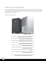
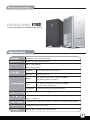
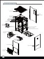
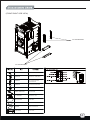
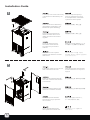
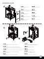
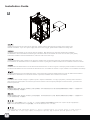
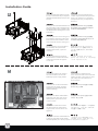
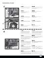
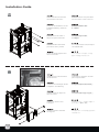
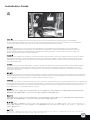
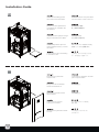
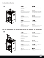
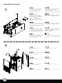
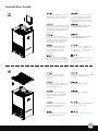
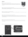
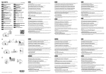
Issue date: December, 2010
FORTRESS SERIES
FT03
MANUAL
G11213300
Installation and system optimization guide:
The following manual and guides were carefully prepared by the SilverStone engineering team to help
you maximize the potential of your SilverStone product. Please keep this manual for future reference
when upgrading or performing maintenance on your system. A copy of this manual can also be
downloaded from our website at:
http://www.silverstonetek.com
1
Specification
P.2
Disassemble chart
P.3
Installation guide
P.5
Connector definition
P.17
Front I/O connector guide
P.19
Component size limitations
P.20
Recommended cooling device setup & selection
P.25
Upgrade and Maintenance
P.28
Q&A
P.31
FORTRESS SERIES
FT03
The new paradigm for desktop computers
Aluminum outer shell, steel body
Micro ATX, Mini-DTX, Mini-ITX
Model No.
SST-FT03B (black)
SST-FT03S (silver)
Exposed
Slot loading slim optical drive x 1
Internal
3.5" x 3, 2.5” x1
Bottom
2 x 120mm intake fans, 1200rpm 22dBA,
2 x 80mm optional fan slots
Top
Hard drive
1 x 120mm exhaust fan, 1200rpm, 22dBA,
1 x 92 / 80mm optional fan
Aluminum side panel heat conduction
4
USB 3.0 x 2 (backwards compatible with USB 2.0)
audio x 1, MIC x 1
Standard PS2 (ATX) up to 180mm (160mm for modular cables) deep
Expansion Card
Compatible up to 13.77” long
235mm (W) x 487mm (H) x 284mm (D)
2
TOP COVER
RIGHT
SIDE PANEL
BACK PANEL
HDD TRAY
USB 3.0 CABLE
RESET SW
POWER SW
120 FAN
120 FAN GUARD
TOP FAN
BRACKET
80 OR 90
FAN (OPTION)
OPTICAL DRIVE BRACKET
SLIM SLOT-LOADING
OPTICAL DRIVE (NOT INCLUDE)
PSU (OPTION)
GPU BASE FAN
BRACKET
120 FAN
FILTER
120 FAN
CPU AREA
FAN BRACKET
LEFT SIDE PANEL
FRONT PANEL
SIDE PANEL
FILTER
3
(FRONT-RIGHT SIDE VIEW)
3.5” HDD BRACKET
3.5” HDD BRACKET
SCREW A
SECURE 2.5” HDD DRIVE
SCREW B
SECURE 3.5” HARD DRIVE
SCREW C
SECURE POWER SUPPLY
OR PSU BRACKET AND
MOTHERBOARD
SCREW D
SECURE MOTHERBOARD
SCREW E
SECURE OPTICAL DRIVE
BUNCH WIRE TIES
SECURE WIRE
2.5” HDD BKT
SECURE 2.5” HDD
ZIPLOCK BAG
PARTS BAG
ZIPLOCK BAG
SCREW BAG
MANUAL
INSTALLATON GUIDE
FAN CABLE
FAN POWER
4
lnstallation Guide
1
Pull the top cover off the case evenly
in the direction as illustrated by the
arrow.
Снимите верхнюю крышку с
корпуса, равномерно потянув
ее в направлении, показанном
стрелкой на иллюстрации.
Ziehen Sie die obere Abdeckung
gleichmäßig in Pfeilrichtung vom
Gehäuse ab (siehe Abbildung).
請按箭頭方向用力,取出上蓋。
Tirez le panneau supérieur en
dehors du boîtier dans le sens
illustré par la flèche de manière
régulière.
请按箭头方向用力,取出上盖。
Tire de la cubierta superior
hacia arriba uniformemente
en la dirección que muestra
la flecha.
矢印によって示される方向に、ケース
の上部カバーを均等に引っ張ります。
Rimuovere il cover superiore
tirandolo nella direzione mostrata
dalla freccia.
케이스의 상부 커버를 그림에
화살표로 표시된 방향으로 일정하게
당겨 제거 합니다.
Pull the side panels up then remove
them outward from the case.
Сместите боковые панели вверх,
а затем снимите их в стороны от
корпуса.
Ziehen Sie die seitlichen Blenden
nach oben, entfernen Sie sie dann
vom Gehäuse.
將左右側板往上推,再取出左右側板。
Tirez les panneaux latéraux puis
retirez-les à l'extérieur du boîtier.
将左右侧板往上推,再取出左右侧板。
Tire de los paneles laterales
hacia arriba y luego sepárelos
de la carcasa.
側面パネルを引き上げてから、
ケースから取り外します。
Tirare i pannelli laterali verso
l’alto quindi rimuoverli dal case.
측면패널을 당겨 바깥쪽으로
제거 합니다.
2
2
1
2
1
5
lnstallation Guide
3
Pull the front panel to remove
from the case.
Снимите переднюю панель
с корпуса.
Ziehen Sie die vordere Blende
zum Entfernen vom Gehäuse ab.
將面板往前拔出。
Tirez le panneau frontal pour le
retirer du boîtier.
将面板往前拔出。
Tire del panel frontal para quitarlo
de la carcasa.
フロントパネルを引いてケース
から取り外します。
Tirare il pannello frontale per
rimuoverlo dal case.
전면패널도 당겨 케이스에서
제거 합니다.
1
1
4
1
2
2
2
3
3
3
2
3
3
Unscrew screws holding the fan bracket and remove
from the case.
Отвинтите винты, удерживающие кронштейн
вентилятора и извлеките его из корпуса.
Lösen Sie die Schrauben, durch welche die Lüfterhalterung
befestigt ist; entfernen Sie die Lüfterhalterung aus dem Gehäuse.
松开所有风扇架螺丝,取下风扇架。
Dévissez les vis fixant la casier du ventilateur et retirez-le du boîtier.
松开所有风扇架螺丝,取下风扇架。
Quite los tornillos que sujetan el bracket del ventilador y
quítelo de la carcasa.
ファンブラケットを保持しているネジ
をはずし、ケースから取り外します。
Svitare le viti che tengono il supporto della ventola e
rimuoverlo dal case.
팬브라켓을 고정하고 있는 나사를 제거하여,
케이스로 부터 제거 합니다.
6
lnstallation Guide
5
Install power supply into the case from the right side. Please note the case supports mounting power supply in two
different orientations. If you use a power supply with 120mm fan or bigger, please install it with the fan facing down.
Installieren Sie das Netzteil von der rechten Seite im Gehäuse. Bitte beachten Sie, dass das Gehäuse die Installation
des Netzteils in zwei verschiedenen Ausrichtungen unterstützt. Falls Sie ein Netzteil mit einem 120 mm-Lüfter (oder größer)
verwenden, installieren Sie das Netzteil bitte so, dass der Lüfter nach unten zeigt.
Installez l'alimentation dans le boîtier par le côté droit. Veuillez noter que le boîtier permet de monter l'alimentation dans deux sens.
Si vous utilisez une alimentation avec un ventilateur de 120mm ou plus grand, veuillez l'installer avec le ventilateur orienté vers le bas.
Instale la fuente de alimentación en la carcasa desde el lado derecho. Por favor, tenga en cuenta que puede montarla en la carcasa en
dos direcciones distintas. Si usa una fuente de alimentación con un ventilador de 120mm ó mayor, instálelo con el ventilador hacia abajo.
Installare l’alimentatore nel case dalla parte destra. Il case supporta il montaggio dell’alimentare secondo due differenti orientamenti.
Se utilizzate un alimentatore con ventola da 120mm o superiore, installatelo con la ventola verso il basso.
Установите блок питания в корпус с правой стороны. Обратите внимание, что корпус допускает установку блока питания в
двух различных ориентациях. Если используется блок питания с вентилятором размером 120 мм или более, установите его
вентилятором вниз.
將電源由右側塞入機殼,請注意,由於電源上方就是光碟槽,所以我們沒有設計正反裝,請先確認好螺絲鎖固孔位再塞入,一般使用12cm
以上風扇的電源而言,風扇朝下。
将电源由右侧塞入机壳,请注意,由于电源上方就是光盘槽,所以我们没有设计正反装,请先确认好螺丝锁固孔位再塞入,一般使用12cm
以上风扇的电源而言,风扇朝下。
右側からケース内に電源をインストールします。ケースでは2つの異なる方向の電源取り付けがサポートされている点にご注意ください。
電源に12cmまたはそれ以上のファンを使う場合、ファンが下に向くようインストールします。
파워서플라이를 오른쪽 방향에서부터 설치합니다. 케이스는 파워서플라이를 두 가지 방향으로 장착할 수 있도록 지원합니다.
만약 120mm 혹은 그 이상의 팬을 사용하는 파워서플라이 사용시에는 팬을 아래쪽으로 향하도록 설치하시기 바랍니다.
7
lnstallation Guide
6
Secure the screws of power supply
and connect the 90 degree power
cord.
Закрепите блок питания винтами
и подсоедините угловой кабель
питания (90 градусов).
Ziehen Sie die Schrauben des
Netzteils fest; schließen Sie das
um 90 Grad angewinkelte Netzkabel
an.
鎖上電源螺絲,插上電源90度接線。
Serrez les vis de l'alimentation et
brancher le cordon d'alimentation
avec le connecteur à 90 degrés.
锁上电源螺丝,插上电源90度接线。
Fije los tornillos de la fuente de
alimentación y conecte el cable
de potencia de 90 grados.
電源のネジを固定し、90度電源コー
ドを接続します。
Fissare l’alimentatore con le viti e
collegare il cavo di alimentazione
con il connettore a 90°.
파워 서플라이를 나사로 고정시킨 후,
90도 꺽인 파워 코드를 연결합니다.
Insert the I/O shield included
with your motherboard.
Вставьте крышку панели вводавывода, входящую в комплект
поставки материнской платы.
Bringen Sie das bei Ihrem
Motherboard mitgelieferte
E/A-Blech an.
將主機板I/O彈片裝上機殼。
Insérez la plaque des entrées/
sorties inclus avec votre carte
mère.
将主机板I/O弹片装上机壳。
Inserte el escudo E/S incluido
con su placa base.
マザーボードに付属のI/Oシール
ドを挿入します。
Inserire la mascherina posteriore
della scheda madre.
메인보드에서 제공하는 I/O
쉴드를 삽입합니다.
7
2
1
8
lnstallation Guide
8
Secure the standoffs with the screws
D on the motherboard tray as required.
Install the motherboard and secure with
screw C.
Закрепите при помощи винтов D
стойки на кронштейне материнской
платы, как требуется. Установите
материнскую плату и закрепите ее
винтом C.
Befestigen Sie die Abstandshalter mit 請依需求將SCREW D的主機板螺柱
den Schrauben D wie erforderlich am 鎖固於機殼,再將主機板裝入機殼,用
Motherboard-Einschub. Installieren Sie SCREW C螺絲將其鎖固。
das Motherboard, befestigen Sie es mit
Schraube C.
Fixez les plots avec les vis de type D
sur le plateau support de carte mère
selon vos besoins. Installez la carte
mère et fixez-la avec les vis de type C.
请依需求将SCREW D的主机板螺柱
锁固于机壳,再将主机板装入机壳,用
SCREW C螺丝将其锁固。
Fije los soportes con los tornillos D
en la bandeja de la placa base.
Instale la placa base y fíjela con
tornillos C.
必要に応じてマザーボードトレイ上に
ネジDでスペーサーを取付けます。マ
ザーボードを取り付けて、ネジCで固
定します。
Avvitare gli standoff sul supporto
scheda madre. Installare la scheda
madre ed assicurarla al supporto
con le viti C.
메인보드 트레이에 지지나사(D)
필요한 만큼 고정시킨 후, 메인보드를
나사로 고정시킵니다(C).
Connect through the two holes to
the motherboard as shown with
24Pin/8pin power supply cables.
Подсоедините к материнской
плате 24-контактный и 8-контактный
кабели питания, пропустив их через
два отверстия, как показано на
иллюстрации.
Verbinden Sie es durch die beiden
Löcher über 24-polige / 8-polige
Netzkabel mit dem Motherboard
(siehe Abbildung).
將電源的24Pin/8pin穿過圖示的兩個
穿線孔,插上主機板。
Branchez les câbles d'alimentation
24Pin/8pin à la carte mère en les
faisant passer par les deux trous
comme montré.
将电源的24Pin/8pin穿过图示的两个
穿线孔,插上主机板。
Conecte los cables de la fuente
de alimentación de 24/8 pines a
la placa base a través de los dos
agujeros.
24ピン/8つのピン電源ケーブルを図示
されるように、マザーボードの2つの
穴を通して接続します。
9
Collegare i connettori di alimentazione 그림에서와 같이 24Pin/8pin 파워
a 24pin ed 8 pin alla scheda madre
케이블을 두개의 구멍을 통과 시킨
facendoli passare per i due fori preposti. 후 메인보드에 연결합니다.
9
lnstallation Guide
10
Connect the audio and front panel
connectors to the motherboard.
Подсоедините к материнской плате
разъемы аудиокабелей и портов на
передней панели.
Verbinden Sie die Audio- und
Frontblendenanschlüsse mit
dem Motherboard.
將AUDIO與Front Panel connector
接線插上主機板。
Branchez les connecteurs audio
et ceux du panneau frontal sur la
carte mère.
将AUDIO与Front Panel connector
接线插上主机板。
Conecte el audio y los conectores
del panel frontal a la placa base.
オーディオおよびフロントパネルコネ
クタをマザーボードに接続します。
Collegare i connettori frontali ed
audio alla scheda madre.
오디오와 전면 패널 커넥터를
메인보드에 연결합니다.
For the compact size of FT03, we
recommend at this point to connect
all SATA cables to the motherboard.
(You are likely to have up to four
connections to make including the
cable from the hot-swappable drive bay)
Так как корпус FT03 имеет компактные
размеры, на этом этапе рекомендуется
подсоединить к материнской плате все
кабели SATA. (Вероятно, потребуется
подсоединить до четырех кабелей,
включая кабель от отсека для диска с
возможностью «горячей» замены.)
USB
CABLE
11
Aufgrund der kompakten Größe des FT03 我們建議你先將以後可能要用的硬碟SATA
empfehlen wir, zu diesem Zeitpunkt alle
線先接上主機板(一般來說最多是4條,包含
SATA-Kabel am Motherboard anzuschließen. 我們一條的熱插拔接線)。
(Sie müssen vermutlich bis zu vier
Verbindungen herstellen, inklusive dem
Kabel vom Hot-Swapping-fähigen
Festplatteneinschub)
A cause de la taille compacte du FT03,
nous vous recommandons de brancher
dés maintenant tous les câbles SATA à
votre carte mère. (Il est probable que
vous utilisiez au moins quatre ports pour
l'utilisation des baies démontables à
chaud (hot-swap)
我们建议你先将以后可能要用的硬盘SATA
线先接上主机板(一般来说最多是4条,包含
我们一条的热插拔接线)。
Debido al tamaño compacto de la FT03,
le recomendamos que conecte en este
momento todos los cables SATA a la
placa base. (Es probable que tenga que
realizar hasta cuatro conexiones incluyendo
el cable de la bahía de dispositivos
cambiables en caliente)
FT03はコンパクトなサイズなので、この
時点で全てのSATAケーブルをマザーボー
ドと接続することをお勧めします。
(ホットスワップドライブベイからのケー
ブルを含めて、最大4つの接続が可能です)
Date le dimensioni compatte di FT03 vi
consigliamo di collegare a questo punto i
cavi serial ATA alla scheda madre. (avete
a disposizione fino a 4 connessioni incluso
il cavo proveniente dal bay hot swappable)
FT03의 컴팩트한 크기로 인해, 모든
SATA 케이블을 메인보드에 연결해 주시기
바랍니다. (대체적으로 핫스왑 드라이브
베이까지 총 4의 연결이 필요할 것입니다.)
10
lnstallation Guide
12
Unscrew screws from the hard
drive bracket to remove it.
Вывинтите винты из кронштейна
жесткого диска, чтобы снять его.
Lösen Sie die Schrauben von der
Festplattenhalterung; entfernen
Sie sie.
鬆開需要的硬碟架的螺絲,
拆下硬碟架。
Dévissez les vis du casier à
disque dur pour le démonter.
松开需要的硬盘架的螺丝,
拆下硬盘架。
Quite los tornillos del bracket
para discos duros y retírelo.
ハードドライブブラケットからネジを外し
てから取り外します。
Svitare le viti dal supporto hard
drive e rimuoverlo.
하드 드라이브 브라켓의 나사를
풀어 브라켓을 제거 합니다.
Install and secure the hard drive
into the bracket.
Установите и закрепите жесткий
диск на кронштейне.
Installieren und befestigen Sie die
Festplatte in der Halterung.
安裝並鎖固需要的硬碟於硬碟架上。
Installez et fixez le disque dur
dans son casier.
安装并锁固需要的硬盘于硬盘架上。
Instale y fije el disco duro
al bracket.
ブラケットにハードドライブをイン
ストールし、固定します。
Installare e fissare l’hard disk
nel supporto.
브라켓에 하드 드라이브를 설치하고
고정시킵니다.
13
11
lnstallation Guide
14
Please make sure to install and connect the 120mm fan into the fan brackets before the graphic/expansion card installation.
Use the include 3pin fan adapter to connect the fans to the power supply if there are not enough fan headers on your motherboard.
If you are not using the 80mm / 92mm fan, you don’t have to install its bracket back into the case.
Bitte achten Sie darauf, den 120 mm-Lüfter in den Lüfterhalterungen zu installieren und anzuschließen, bevor Sie die Grafik-/
Erweiterungskarte installieren. Schließen Sie die Lüfter über den mitgelieferten 3-poligen Lüfteradapter am Netzteil an, falls nicht
genügend Lüfter-Header an Ihrem Motherboard vorhanden sind. Falls Sie den 80 mm- / 92 mm-Lüfter nicht nutzen, müssen Sie
dessen Halterung nicht wieder im Gehäuse installieren.
Vérifiez bien que ventilateur de 120mm est correctement installé et branché dans le casier des ventilateurs avant de monter les carte(s)
graphiques et d'extensions. Utilisez l'adaptateur inclus 3pin pour brancher les ventilateurs à l'alimentation s'il n'ya pas assez de ports
disponible sur votre carte mère. Si vous ne souhaitez pas utiliser le ventilateur de 80mm / 92mm, vous n'avez pas besoin de remettre
son casier dans le boîtier.
Tenga en cuenta por favor que debe instalar y conectar el ventilador de 120mm en el bracket para ventilador antes de instalar la tarjeta
gráfica ó de expansión. Use el adaptador incluido de 3 pines para conectar los ventiladores a la fuente de alimentación si no tiene
suficientes enganches para ventiladores en su placa base. Si no está usando el ventilador de 80/92mm, no tiene que volver a instalar
su bracket en la carcasa.
Assicuratevi di installare e connettere la ventola da 120mm nel supporto ventola prima di montare la scheda grafica/scheda di espansione.
Utilizzare l’adattatore a 3pin per connettere la ventola all’alimentatore qualora non vi fossero abbastanza connessioni sulla scheda madre.
Se non utilizzate la ventola da 80/92mm non dovete installare il supporto nel case.
Обязательно установите на кронштейны вентилятора и подключите 120-мм вентилятор до установки видеокарты и плат расширения.
Используйте входящий в комплект 3-контактный переходник для вентилятора, чтобы подключить вентиляторы к блоку питания, если
на материнской плате недостаточно разъемов для вентиляторов. Если вентилятор размером 80 или 92 мм не используется, его
кронштейн можно не устанавливать обратно в корпус.
在想安裝介面卡之前,先連接上所有120mm風扇的線材,把120mm風扇架裝上(如果主機板的2510 3Pin插做不夠用可以利用我們零件包的
電源轉接線,如果沒有要用到顯示卡上方的80mm/92mm風扇,風扇架可以不用裝回機殼,收好)。
在想安装适配卡之前,先连接上所有120mm风扇的线材,把120mm风扇架装上(如果主机板的2510 3Pin插做不够用可以利用我们零件包的
电源转接线,如果没有要用到显示卡上方的80/92mm风扇,风扇架可以不用装回机壳,收好)。
グラフィック/拡張カードの装着前に、必ずファンブラケット内に120mmのファンをインストールし、接続してください。マザーボードに十分なファンヘッ
ダがない場合、付属の3ピンファンアダプタを使用してファンを電源と接続します。80mm/92mmのファンを使っていないならば、ケース内にブラケット
を戻す必要はありません。
그래픽 카드 / 확장카드 설치 전에 반드시 120mm 팬을 팬브라켓에 설치 하기 바랍니다. 메인보드에 팬 연결 단자가 모자란 경우
동봉된 3핀 팬 어댑터를 이용해 팬을 전원에 연결하시기 바랍니다.
12
lnstallation Guide
15
Insert the slot loading optical
drive and connect the cables.
Вывинтите винты из кронштейна
жесткого диска, чтобы снять его.
Stecken Sie das optische SlotIn-Laufwerk ein, schließen Sie
die Kabel an.
將光碟機塞入機殼,
接上電源與傳輸排線。
Insérez le lecteur optique "mangedisque" et branchez les câbles.
将光驱塞入机壳,
接上电源与传输排线。
Instale el dispositivo óptico de
carga mediante ranura y conecte
los cables.
スロットローディング光学ドライブを
装着し、ケーブルを接続します。
Inserire il drive ottico slot loading
e connettere i cavi.
슬롯로딩 광드라이브를 삽입한
후, 케이블을 연결합니다.
Place the front panel back
onto the case.
Установите и закрепите жесткий
диск на кронштейне.
Bringen Sie die Frontblende
wieder am Gehäuse an.
將前面板蓋上。
Remettez le panneau frontal
dans le boîtier.
将前面板盖上。
Vuelva a poner el panel
frontal en la carcasa.
ケースにフロントパネルを
戻します。
Riposizionare il pannello frontale
sul case.
전면패널을 케이스에 재
장착합니다.
16
13
lnstallation Guide
17
Please use the appropriate
screwdriver to secure the
optical drive.
При помощи подходящей отвертки
закрепите оптический привод.
Bitte nutzen Sie zum Befestigen
des optischen Laufwerks einen
geeigneten Schraubendreher.
調整好光碟機的位置並將光碟機螺
絲鎖上(這時請用最小的螺絲起子)。
Veuillez utiliser le tournevis
approprié pour fixer le lecteur
optique.
调整好光驱的位置并将光驱螺丝
锁上(这时请用最小的螺丝起子)。
Por favor, use el destornillador
apropiado para fijar el dispositivo
óptico.
適切なドライバーを使って光学ドラ
イブを固定します。
Utilizzare l’apposito cacciavite
per montare il drive ottico.
적정한 스크류 드라이브를 이용해
광드라이브를 고정시킵니다.
Release the screws holding the
expansion slot covers.
Отвинтите винты, удерживающие
крышки слотов расширения.
Lösen Sie die Schrauben,
über die die Blenden der
Erweiterungssteckplätze
befestigt sind.
請卸下擴充槽檔片螺絲。
Dévissez les vis fixant les caches
des emplacements d'extension.
请卸下扩充槽档片螺丝。
Quite los tornillos que sujetan
las cubiertas de las ranuras de
expansión.
拡張スロットカバーを固定してい
るネジを外します。
Svitare le viti che tengono i cover
degli slot.
확장슬롯 커버를 고정하고 있는
나사를 풉니다.
18
1
1
2
14
lnstallation Guide
19
1
2
2
Remove the slot covers and install
any required expansion cards.
Then reinstall slot covers back onto
any unused expansion slots and
secure with included screws.
Удалите крышки слотов и установите
необходимые платы расширения.
Затем установите крышки на
незадействованные слоты расширения
и закрепите их прилагающимися винтами.
Entfernen Sie die Blenden der
Steckplätze; installieren Sie alle
erforderlichen Erweiterungskarten.
Bringen Sie die Blenden anschließend
bei allen nicht verwendeten
Erweiterungssteckplätzen wieder an;
befestigen Sie sie mit den mitgelieferten
Schrauben.
移除擴充槽檔片並安裝擴充卡,未使用的
擴充槽請將檔片裝回並以內附螺絲鎖固。
Retirez les équerres et installez à la place 移除扩充槽档片并安装扩充卡,未使用的
vos cartes d'extension. Puis réinstallez les 扩充槽请将档片装回并以内附螺丝锁固。
équerres dans les emplacements inutilisés
et fixez-les avec les vis incluses.
Quite las cubiertas de las ranuras e
instale cualquier tarjeta de expansión.
A continuación reinstale las cubiertas
en cualquier ranura que no haya usado
y fíjelas con los tornillos incluidos.
スロットカバーを取り外し、必要とされてい
る拡張カードを装着します。そして、未使用
の拡張スロットにはスロットカバーを戻し、
付属のネジで固定します。
Rimuovere i cover degli slot ed installare
le schede di espansione previste.
Quindi reinstallare i cover rimossi nelle
sedi rimaste inutilizzate.
슬롯 커버를 제거한 후, 필요한 확장
카드를 설치합니다. 이후, 슬롯 커버를
재 장착한 후, 사용하지 않는 확장슬롯은
슬롯 커버로 막고 나사로 고정시킵니다.
Place the side panels back
onto the case.
Установите боковые панели
на корпус.
Bringen Sie die seitlichen Blenden
wieder am Gehäuse an.
將左右側板裝回。
Remettez les panneaux latéraux
dans le boîtier.
将左右侧板装回。
Vuelva a poner los paneles
laterales en la carcasa.
ケースに側面パネルを戻します。
Riposizionare i pannelli laterali.
측면패널을 케이스에 재 장착합니다.
20
1
2
1
15
2
lnstallation Guide
21
Open the hot-swappable cage and
install the 3.5” hard drive (make sure
the hard drive sticker faces out).
Откройте отсек с возможностью
«горячей» замены и установите
в него 3,5-дюймовый жесткий
диск (наклейка жесткого диска
должна быть направлена наружу).
Öffnen Sie den Hot-Swapping-fähigen 打開熱插拔插槽,將3.5”塞入機殼
Käfig und installieren Sie die 3,5 Zoll- (注意硬碟的貼紙面在外邊)。
Festplatten (achten Sie darauf, dass
der Aufkleber der Festplatte nach
außen zeigt).
Ouvrez le casier des lecteurs
démontables à chaud et installez-y
vos disques durs 3.5” (vérifiez bien
les autocollants des disques durs
sont orientés vers l'extérieur).
打开热插拔插槽,将3.5”塞入机壳
(注意硬盘的贴纸面在外边)。
Abra la carcasa cambiable en
caliente e instale el disco duro
de 3,5” (asegúrese de que la
pegatina del disco duro está
hacia fuera).
ホットスワップケージを開き、3.5
インチハードドライブをインストー
ルします(ハードドライブステッカ
ーの側を外側にしてください)。
Aprire il supporto hot swappable
per hard drive da 3,5” ed installare
l’hard disk. (assicurarsi che l’adesivo
dell’hard disk sia rivolto verso l’alto).
핫스왑 케이지를 열고 3.5” 하드
드라이브를 설치 합니다. ( 하드
드라이브 스티커가 바깥쪽으로
나오도록 설치합니다. )
Place the top cover back onto
the case evenly to complete
installation.
Завершите сборку, ровно установив
на корпус верхнюю крышку.
Zum Abschluss der Installation
bringen Sie die obere Abdeckung
wieder am Gehäuse an.
將上蓋裝回機殼,完成組裝。
Remettez le panneau supérieur
dans le boîtier en le poussant de
manière régulière pour terminer
l'installation.
将上盖装回机壳,完成组装。
Vuelva a poner la cubierta en la
carcasa uniformemente para
completar la instalación.
ケースに上部カバーを水平に戻すと、
インストールは完了です。
Riposizionare il cover superiore
per completare l’installazione.
상부 커버를 케이스에 장착한 후
설치를 마칩니다.
22
16
Connector definition
(1) Front panel connector installation
Power switch and reset switch installation guide:
Please refer to the motherboard manuals for the motherboard’s “Front Panel Connector” or “System Panel Connector” pin definition.
Power switch and reset switch have no polarity, so they can be connected in any orientation.
Ein-/Ausschalter und Rücksetztaste (Reset) installieren:
Bitte suchen Sie in der Motherboard-Dokumentation nach der Pinbelegung der Anschlüsse des Frontbedienfeldes („Front Panel Connectors“
oder „System Panel Connectors“). Ein-/Austaste und Rücksetztaste benötigen keine bestimmte Polarität, können daher beliebig (ohne auf +
und - zu achten) angeschlossen werden.
Guide d'installation des interrupteurs d'allumage et de réinitialisation :
Veuillez-vous référer au manuel de votre carte mère pour la description des broches "des connecteurs du panneau frontal" et des broches
"des connecteurs du panneau système". Les interrupteurs d'allumage et de réinitialisation ne possède pas de polarité, donc ils peuvent être
branché dans les deux sens.
Guía de instalación de los interruptores de encendido y reseteo:
Por favor, consulte en los manuales de la placa base la configuración de pines del “Conector de panel frontal” ó “Conector de panel de sistema”
de su placa base. Los interruptores de encendido y reseteo no tienen polaridad, luego se pueden conectar con cualquier orientación.
Guida all’installazione dei connettori Power Switch e Reset Switch:
Fare riferimento al manuale della scheda madre nella sezione “Connettori del pannello frontale” o “Connettori del pannello di sistema”.
Power switch e reset switch non hanno polarità, posso essere pertanto connessi con qualsiasi orientamento.
Инструкция по подключению выключателя питания и кнопки перезагрузки (reset):
Описание контактов разъемов приведены в разделах “Разъемы передней панели” или “Разъемы системной панели” руководства
пользователя материнской платы. Выключатель питания и кнопка перезагрузки не имеют полярности, поэтому их можно подключать
в любой ориентации.
Power Switch 與Reset Switch安裝說明:
請參考主機說明書的Front Panel Connectors安裝Pin Define,將Connector插上;Power Switch 與Reset Switch並無正負極性之分,
反插正插都不影響功能性。
Power Switch 与Reset Switch安装说明:
请参考主机说明书的Front Panel Connectors安装Pin Define,将Connector插上;Power Switch 与Reset Switch并无正负极性之分,
反插正插都不影响功能性。
電源スイッチおよびリセットスイッチのインストールガイド:
マザーボードの「フロントパネルコネクタ」または「システムパネルコネクタ」のピン配列についてはマザーボードマニュアルを参照
してください。電源スイッチとリセットスイッチに極性はないので、いずれの方向でも接続できま。
파워 스위치 및 리셋 스위치 설치 가이드:
메인보드 매뉴얼의 전면패널 커넥터 혹은 시스템패널 커넥터 핀을 참조하기 바랍니다. 파워 스위치와 리셋 스위치는 극성이 없어
어떤 방향으로 설치해도 무방합니다.
17
Connector definition
LED connector installation guide:
Please refer to the motherboard manuals for the motherboard’s “Front Panel Connector” or “System Panel Connector” pin definition.;
the white wires are negative while other colors are positive wires. The Power LED wires are separate pins for compatibility with different
motherboard pin definition so please make sure they are connected in the right polarity by referring to your motherboard manual.
LED-Verbinder installieren:
Bitte suchen Sie in der Motherboard-Dokumentation nach der Pinbelegung der Anschlüsse des Frontbedienfeldes („Front Panel Connectors
“ oder „System Panel Connectors“). Die weißen Adern sind negativ (-), die farbigen Adern positiv (+).Die Kabel für die Betriebsanzeige-LED
sind zur Kompatibilität mit unterschiedlichsten Motherboards einzeln, nicht als kompletter Stecker ausgeführt. Achten Sie hier bitte auf die
richtige Polarität, lesen Sie in der Dokumentation Ihres Motherboards nach.
Guide d'installation du connecteur LED :
Veuillez-vous référer au manuel de votre carte mère pour la description des broches "des connecteurs du panneau frontal" et des broches
"des connecteurs du panneau système". Les câbles colorés en blanc sont négatifs alors que ceux d'une autre couleur sont positifs.Les
câbles de la LED Power sont séparés afin d'être compatible avec différentes cartes mères, donc vérifiez bien qu'ils sont branchés avec la
bonne polarité en vous référant au manuel de votre carte mère.
Guía de instalación del conector LED:
Por favor, consulte en los manuales de la placa base la configuración de pines del “Conector de panel frontal” ó “Conector de panel de sistema
” de su placa base. Los cables de color blanco son negativos mientras que los de color son positivos.Los cables LED de potencia tienen pines
separados para compatibilidad con diferentes definiciones de pines de la placa base luego por favor, asegúrese de que están conectados en la
polaridad correcta consultando el manual de su placa base.
Guida all’installazione del connettore LED
Fare riferimento al manuale della scheda madre nella sezione “Connettori del pannello frontale” o “Connettori del pannello di sistema”. I cavi
di colore bianco sono il polo negativo, mentre quelli di colore diverso il positivo.Guida all’installazione del Power Led serie RV/KLConnettere
direttamente il connettore ad un molex dell’alimentatore
Инструкция по подключению коннектора для светодиодного индикатора питания:
Описание контактов разъемов приведены в разделах “Разъемы передней панели” или “Разъемы системной панели” руководства
пользователя материнской платы. Белые провода - отрицательной полярности, цветные провода - положительной полярности.
Провода светодиодного индикатора питания имеют отдельные контакты для совместимости с различными типами контактов
материнских плат, поэтому обратитесь к руководству пользователя материнской платы и убедитесь, что полярность соблюдена.
LED接頭安裝說明:
請參考說明書的Front Panel Connectors安裝Pin Define,將Connector插上;白色線的部分為負極,彩色線的部分是正極。Power LED為了
適應各主機板的不同,特別設計為散Pin樣式,請安心使用。。
LED接口安装说明:
请参考说明书的Front Panel Connectors安装Pin Define,将Connector插上;白色线的部份为负极,彩色线的部份为正极。Power LED为了
适应主机板的不同,特别设计为散Pin样式,请安心使用。
LEDコネクタのインストールガイド:
マザーボードの「フロントパネルコネクタ」または「システムパネルコネクタ」ピン配列についてはマザーボードマニュアルを参照してく
ださい。白色のリード線はマイナスで、色の着いたリード線がプラスです。電源LEDリード線は種々のマザーボードピン定義と互換性を持た
せるため分離されたピンとなっているので、ご使用のマザーボードマニュアルを参照して、 適切な極性に接続されるようお確かめください。
LED커넥터 설치 가이드:
메인보드 매뉴얼의 전면패널 커넥터 혹은 시스템패널 커넥터 핀을 참조하기 바랍니다. 하얀선의 경우 음극이며, 다른 색의 경우
양극입니다. 파워 LED 선은 분리되어 다양한 메인보드에서 동작할 수 있도록 되어 있습니다. 그러므로 메인보드 매뉴얼을 참조하여
올바를 극성을 주의해 선택하시기 바랍니다.
18
Front I/O connector guide
Below are the front I/O connectors pin definition, please also check your motherboard manual to cross reference with motherboard’s
front I/O pin headers. SilverStone’s I/O connectors are in block type to simplify installation.
Nachstehend finden Sie die Pinbelegung der vorderen E/A-Anschlüsse; bitte gleichen Sie zudem das Handbuch Ihres Motherboards mit
den vorderen E/A-Pinzuweisungen ab. SilverStones E/A-Anschlüsse befinden sich zur Vereinfachung der Installation in Blockart.
Au dessous de la description des broches des ports d'E/S, veuillez aussi vérifier sur le manuel de votre carte mère de manière croisée
que les broches sont correctement placées. Les connecteurs d'E/S de SilverStone sont en bloc pour en simplifier leur installation.
A continuación se detallan los pines para conectores E/S frontales, compruebe también por favor el manual de su placa base para
cotejar los pines E/S frontales de la misma. Los conectores E/S de SilverStone son del tipo bloque para simplificar la instalación.
Di seguito lo schema delle connessioni I/O frontali, confrontare lo schema con quanto riportato sul manuale della scheda madre per
effettuare un controllo incrociato. I connettori I/O Silverstone, per semplificare l’installazione, sono del tipo “a blocco”.
Ниже приведено описание контактов передних разъемов ввода/вывода. Обратитесь также к руководству пользователя материнской
платы за описанием передних разъемов ввода/вывода типа "пин-хедер". Разъемы ввода/вывода "SilverStone" - блочного типа, что
облегчает сборку.
下表為Front I/O Connectors的Pin Define,請參閱主機板說明書的各Front I/O Connectors Pin Define一一核對。
FT03的Front I/O Connectors完全採用集合Pin方式以簡化安裝。
下表为Front I/O Connectors的Pin Define,请参阅主机板说明书的各Front I/O Connectors Pin Define一一核对。
FT03的Front I/O Connectors完全采用集合Pin方式以简化安装。
以下はフロントI/Oコネクタピン配列ですが、お持ちのマザーボードのフロントI/Oピンヘッダは、マザーボードマニュアルをご参照
ください。シルバーストーンのI/Oコネクタは、インストールの容易なブロックタイプになっています。
아래는 전면 I/O 커넥터의 핀 사양입니다. 메인보드 매뉴얼을 참조해, 메인보드의 전면 I/O 핀사양을 재 확인한
후 설치합니다. SilverStone의 I/O 커넥터는 블록 타입으로 구성되어 있어 간편한 설치가 가능합니다.
USB 3.0 CONNECTION
19
Component size limitations
(1) CPU Cooler limitation
5mm
167mm
MOTHERBOARD
MOTHERBOARD
LEFT SIDE PANEL
RIGHT SIDE PANEL
BACK PANEL
FRONT PANEL
The FT03 has 167mm height limitation for CPU cooler. The cooler can protrude 5mm over the motherboard edge.
Das FT03 unterstützt beim CPU-Kühler eine Maximalhöhe von 167 mm. Der Kühler kann 5 mm über die Motherboard-Kante hinausstehen.
Le FT03 ne peut accueillir que les dissipateurs de processeur d'une taille inférieure ou égale à 167mm. Le dissipateur peut dépasser de
5 mm par rapport aux bords de la carte mère.
La FT03 tiene una limitación de altura de 167mm para el disipador de la CPU. El disipador puede sobresalir 5mm sobre el borde de
la placa base.
In FT03 l’altezza del dissipatore CPU è limitata a 167mm. Il dissipatore può sporgere 5mm dai bordi della scheda madre.
В корпус FT03 можно установить процессорный кулер высотой не более 167 мм. Кулер может выступать на 5 мм за край
материнской платы.
Cooler限高是167mm,Cooler外緣允許超出主機板上邊界5mm。
Cooler限高是167mm,Cooler外缘允许超出主机板上边界5mm。
FT03はCPUクーラーを対照として167mmの高さ制限があります。クーラーはマザーボードエッジから5mm突出させることができます。
FT03은 CPU쿨러의 높이 제한이 167mm 입니다. 쿨러는 메인보드 가장자리로 부터 5mm 정도 나와도 무방합니다.
20
Component size limitations
(2) PSU limitation
LEFT SIDE PANEL
RIGHT SIDE PANEL
180mm
PSU BRACKET
215mm
A: The FT03 supports power supply with depth of up to 215mm. The limitation of power supplies with modular cables is 180mm. We use a specific extension cord for connecting
to power supply’s AC plug, so it does not support large, specialized plug found in extremely high wattage power supplies (e.g. SilverStone ST1500). If high wattage power supply
is required, we recommend the Strider Gold ST1200-G, which conforms to FT03’s dimension and extension power cord requirements.
B: We recommend using the PP05 short cable kit in addition to its compatible power supply model to reduce cable clutter during installation.
A: Das FT03 unterstützt Netzteile mit einer Tiefe von bis zu 215 mm. Die Begrenzung von Netzteilen mit modularen Kabeln beträgt 180 mm. Wir verwenden ein spezifisches
Verlängerungkabel zum Anschließen am AC-Netzteilstecker; daher werden keine großen, spezialisierten Stecker unterstützt, die bei Netzteilen mit sehr hoher Wattzahl (z. B.
dem SilverStone ST1500) verbaut sind. Falls Sie ein Netzteil mit hoher Wattzahl benötigen, empfehlen wir das Strider Gold ST1200-G; dieses stimmt mit den Abmessungen
des FT03 sowie den Anforderungen an das Verlängerungsnetzkabel überein.
B: Wir empfehlen zur Reduzierung von „Kabelsalat“ während der Installation den Einsatz des PP05-Sets (kurze Kabel) in Verbindung mit einem kompatiblen
Netzteilmodell.
A: Le FT03 est compatible avec les alimentations d'une profondeur inférieure ou égale à 215mm. Pour les alimentations à câblage modulaire le maximum est de 180mm.
Nous utilisons une rallonge spécifique pour brancher l'alimentation à la prise secteur, donc il n'est pas compatible avec les cordons plus grand, les connecteurs spécialisés
trouvés dans les alimentations très puissantes (par ex: SilverStone ST1500). Si une alimentation à très forte puissance est nécessaire, nous vous recommandons la Strider
Gold ST1200-G, qui est compatible avec les contraintes du FT03, à savoir les dimensions et le cordon d'alimentation.
B: Nous vous recommandons l'utilisation du kit de câbles court PP05 qui en plus d'être compatible avec les tous les modèles d'alimentation permet de réduire l'encombrement
des câbles pendant l'installation.
A: La FT03 acepta fuentes de alimentación con una profundidad de hasta 215mm. La limitación para las fuentes de alimentación con cables modulares es de 180mm. Ya
que usamos un cable de extensión específico para conectar el enchufe AC de la fuente de alimentación, no se pueden usar los enchufes grandes y especializados que se
encuentran en las fuentes de alimentación de alta potencia (como la Silverstone ST1500). Si necesita una fuente de alimentación de alta potencia, le recomendamos la
Strider Gold ST1200-G, que se adapta a las dimensiones de la FT03 y los requisitos del cable de potencia.
B: Le recomendamos usar el kit de cable corto PP05 además de su modelo de fuente de alimentación compatible para reducir el revoltijo de
cables durante la instalación.
A: FT03 supporta alimentatori con profondità fino a 215mm. La limitazione per gli alimentatori con connessioni modulari è di 180mm. Utilizziamo un cavo specifico per connettere
l’alimentazione al plug AC, quindi non sono supportati i plug specifici utilizzati negli alimentatori ad elevato wattaggio (come ad esempio il SilverStone ST1500). Se avete bisogno
di un alimentatore ad elevata potenza vi raccomandiamo il modello Strider Gold ST1200-G, che si adatta alle dimensioni ed al formato del cavo di alimentazione.
B: Vi raccomandiamo di utilizzare il kit cavi corti PP05 in aggiunta a modelli di alimentatori compatibili per ridurre l’ingombro dei cavi durante l’installazione.
A: Корпус FT03 допускает установку блока питания глубиной до 215 мм. Глубина блока питания с модульными кабелями не должна превышать 180 мм. Мы
используем специальный удлинительный кабель, подсоединяемый к розетке переменного тока блока питания, поэтому невозможно использовать особую большую
розетку, которая имеется на блоках питания сверхвысокой мощности (например, SilverStone ST1500). Если требуется установить блок питания высокой мощности,
рекомендуется использовать блок питания Strider Gold ST1200-G, соответствующий размерам корпуса FT03 и допускающий подключение удлинительного кабеля питания.
B: Помимо совместимого блока питания рекомендуется использовать комплект коротких кабелей PP05 с целью более аккуратной прокладки кабелей.
A. 長度限制:FT03的PSU可用總空間有215mm,使用模組化電源長度不超過180mm,無論如何,我們最推薦使用Strider Plus系列電源,而FT03因為內部採用電源延長接頭,
所以不支援需要大方型電源接頭的電源供應器(例如ST1500)。如果需要最高瓦數的電源,建議使用SST-ST1200-G金牌1200W電源。
B. 電源線材建議長度:本機殼完全配合PP05短線包設計,我們建議購買短線包,以減少線材長度。
A. 长度限制:FT03的PSU可用总空间有215mm,使用模块化电源长度不超过180mm,无论如何,我们最推荐使用Strider Plus系列电源,而FT03因为内部采用电源延长接头,
所以不支持需要大方型电源接头的电源供应器(例如ST1500)。如果需要最高瓦数的电源,建议使用SST-ST1200-G金牌1200W电源。
B. 电源线材建议长度:本机壳完全配合PP05短线包设计,我们建议购买短线包,以减少线材长度。
A: FT03は最高215mmの奥行きの電源をサポートします。モジュラーケーブル付き電源の限界は180mmです。電源のACプラグと接続するのに専用延長コードを使うので、
極めて高いワット数電源(??SilverStone ST1500)に見られる大型で専用のプラグはサポートしません。高ワット数の電源が必要とされる場合、FT03のサイズと延長電源コ
ード必要条件に対応しているStrider Gold ST1200-Gを推奨します。
B:インストールの際にケーブルのからまりを減少させるため、互換の電源モデルに加えてPP05ショートケーブルキットのご使用をお勧めます。
A: FT03은 215mm의 깊이를 갖는 파워 서플라이까지 지원합니다. 모듈러 케이블을 사용하는 파워 서플라이는 180mm의 깊이 제한이 있습니다. AC전원과 파워 서플라이를 연결하는
특수한 연장 케이블을 사용하기 때문에, 용량이 큰 파워 서플라이 (예. SilverStone ST1500) 에서 사용하는 큰 플러그를 지원하지 않습니다. 고용량의 파워 서플라이를 꼭 사용해야
한다면, FT03의 규격과 확장 케이블 규격을 지원하는 Gold ST1200-G 사용을 권장합니다.
B: 설치중 케이블 정리를 원활하게 하기 위해, PP05 Short 케이블 키트를 사용하기를 권장합니다.
21
Component size limitations
(3) Hard drive thickness limitation
FT03’s 3.5” hard drive bay is designed for hard drives with 25.4mm thickness, we do not recommend using thinner hard drives due to:
1. Insecure mounting with the hot-swappable hard drive cage.
2. Thinner hard drives will be unable to take advantage of FT03’s aluminum block on the side panel for passive cooling.
Der 3,5 Zoll-Festplatteneinschub des FT03 dient dem Einsatz von Festplatten mit einer Dicke von 25,4 mm; wir raten aus folgenden Gründen
von der Verwendung dünnerer Festplatten ab:
1. Unsichere Montage im Hot-Swapping-fähigen Festplattenkäfig.
2. Dünnere Festplatten können nicht vom passiven Kühleffekt des an der seitlichen Blende befindlichen Aluminiumblocks im FT03 profitieren.
La baie a disques dur 3.5” du FT03 est conçu pour les disques durs d'une épaisseur de 25.4mm, nous ne vous recommandons pas d'utiliser
des disques durs plus fins à cause de:
1. Montage non sécurisé dans le casier démontable à chaud.
2. Les disques durs plus fins ne pourront pas tirer avantage du bloc en aluminium du FT03 du panneau latéral pour le refroidissement passif.
La bahía para discos duros de la FT03 está diseñada para discos duros con un grosor de 25,4mm, no le recomendamos que use discos duros
más delgados porque:
1. No es seguro montarlos con la carcasa para discos duros cambiables en caliente.
2. Los discos duros más delgados no podrán aprovecharse del bloque de aluminio de la FT03 en el panel lateral para refrigerarse de forma pasiva.
Il drive bay da 3,5” di FT03 è disegnato per accogliere hard disk spessi 25,4mm, vi raccomandiamo di non utilizzare hard disk più sottili per
i seguenti motivi:
1. Montaggio poco sicuro nel supporto hot swappable.
2. Hard disk più sottili non gioveranno del raffreddamento passivo fornito dal blocco di alluminio posto sul pannello laterale.
Отсек для 3,5-дюймовых жестких дисков корпуса FT03 предназначен для жестких дисков толщиной 25,4 мм. Использовать жесткие
диски меньшей толщины не рекомендуется по следующим причинам:
1. ненадежное крепление на отсек для жестких дисков с возможностью горячей замены;
2. жесткие диски меньшей толщины не позволяют использовать преимущество пассивного охлаждения посредством алюминиевого
блока, расположенного на боковой панели корпуса FT03.
本機殼的3.5” Bay設計是配合約25.4mm厚度的硬碟為主,如果使用太薄的3.5” 硬碟:
1. 以熱插拔硬碟而言無法固定。
2. 另外兩顆3.5” 硬碟的散熱也是靠鋁側板,使用過薄的硬碟會降低散熱效果。
本机壳的3.5” Bay设计是配合约25.4mm厚度的硬盘为主,如果使用太薄的3.5” 硬盘:
1. 以热插拔硬盘而言无法固定。
2. 另外两颗3.5” 硬盘的散热也是靠铝侧板,使用过薄的硬盘会降低散热效果。
FT03の3.5インチハードドライブベイは25.4mm厚のハードドライブ用に設計されており、より薄いハードドライブの使用は以下の理由
により推奨されません:
1. ホットスワップハードドライブケージへの不安定な取付け。
2. より薄いハードドライブでは、FT03の側面パネルにあるアルミニウムブロックの受動冷却特性が発揮されません。
FT03의 3.5” 하드 드라이브 베이는 25.4mm의 하드 두께를 지원하도록 제작되었으며, 이보다 두께가 얇은 하드 드라이브 사용을 다음 이유로
권장하지 않습니다:
1. 핫스왑 하드 드라이브 케이지 고정이 불확실합니다.
2. 얇은 하드 드라이브는 FT03의 측면판넬의 알루미늄 블록에 의한 간접 냉각의 장점을 활용할 수 없습니다.
22
Component size limitations
(4) VGA card length limitation
MOTHERBOARD
MOTHERBOARD
BACK PANEL
FRONT PANEL
LONG GRAPHICS
BACK PANEL
LONG GRAPHICS
FRONT PANEL
120 FAN
80 FAN
FT03 can support 13.77” consumer level graphics cards
Graphic card length reference:
AMD Radeon HD 5970 – 12.2 "
NVidia Geforce GTX480 – 10.5”
AMD Radeon HD 5870 – 11”
AMD Radeon HD 5850 – 9.5””
AMD Radeon HD 6870 – 10.5”
NVidia Geforce GTX470 – 9.5”
NVidia Geforce GTX580 – 10.5”
AMD Radeon HD 6850 – 9”
If you use the angled 120mm intake fan bracket, then you can only install a long graphic card up to 12.2 inch into the first PCI-E slot. To install dual graphic cards for
CrossFire or SLI, the 120mm intake fan bracket needs to be removed and replaced with two 80mm fans on the bottom of the FT03.
Wenn Sie die angewinkelte 120 mm-Zuluft-Lüfterhalterung verwenden, können Sie eine lange Grafikkarte von bis zu 12,2 Zoll nur im ersten PCI-E-Steckplatz installieren.
Falls Sie zur Nutzung von CrossFire oder SLI zwei Grafikkarten installieren möchten, müssen Sie die 120 mm-Zuluft-Lüfterhalterung entfernen und durch zwei 80 mmLüfter an der Unterseite des FT03 ersetzen.
Si vous utilisez le casier incliné du ventilateur d'admission de 120mm, alors vous pouvez seulement installé une carte graphique d'une longueur d'au plus 12.2 pouces
dans le premier emplacement PCI-E. Pour installer deux cartes graphiques de type CrossFire ou SLI, le ventilateur d'admission de 120mm a besoin d'être retiré et
remplacé par deux ventilateurs de 80mm dans le bas du FT03.
Si usa el bracket en ángulo para el ventilador de entrada de 120mm, tendrá que instalar una tarjeta gráfica con una longitud de hasta 12,2” en la primera ranura PCI-E.
Para instalar tarjetas gráficas duales para Crossfire ó SLI, el bracket para ventiladores de entrada de 120mm debe ser retirado y reemplazado con dos ventiladores de
80mm en la parte inferior de la FT03.
Se utilizzate il supporto angolato per la ventola da 120mm, potete installare soltanto una scheda grafica lunga fino a 30.99cm nel primo slot PCI-E. Per installare un
sistema dual vga Crossfire o SLI, il supporto angolato per la ventola da 120mm deve essere rimosso e rimpiazzato con due ventole da 80mm sul fondo di FT03.
Если используется угловой кронштейн для 120-мм впускного вентилятора, то длинную видеокарту длиной до 12,2 дюйма можно установить только в первый
слот PCI-E. Для установки видеокарт в конфигурации CrossFire или SLI кронштейн для 120-мм впускного вентилятора необходимо снять и заменить двумя
80-мм вентиляторами в нижней части корпуса FT03.
如果顯示卡進風風扇要使用120mm風扇,長顯示卡只能安裝在第一槽位,請先確認主機板再購買,如果要使用長的顯示卡或是安裝雙卡使用,可以將120mm風扇拆掉,
用兩顆80mm風扇取代。
如果显示卡进风风扇要使用120mm风扇,长显示卡只能安装在第一槽位,请先确认主机板再购买,如果要使用长的显示卡或是安装双卡使用,可以将120mm风扇拆掉,
用两颗80mm风扇取代。
アングル付き120mm給気ファンブラケットを使うなら、第1のPCI-Eスロットにのみ最高12.2インチまでの長尺グラフィックカードをインストールできます。
CrossFireまたはSLIのためのデュアルグラフィックカードをインストールするには、120mm給気ファンブラケットを取り外して、FT03の底部に2つの80mm
ファンを設置する必要があります。
각이 진 120mm 흡기 팬브라켓 을 사용한다면, 12.2인치 까지의 긴 그래픽 카드를 PCI-E 슬롯에 설치 할 수 있습니다. Cross Fire나 SLI를 위한 듀얼
그래픽 카드 사용시에는 120mm 흡기 팬 브라켓을 제거한 후 두개의 80mm 팬을 FT03의 바닥에 장착하시기 바랍니다.
23
Component size limitations
(5) Optical drive limitation
(please use software to eject optical disk)
The FT03 only supports slim
“slot-loading” optical drives.
Корпус FT03 допускает только
установку тонких оптических
приводов со «щелевой загрузкой».
Das FT03 unterstützt nur schmale
optische Laufwerke („Slot-In“).
FT03只能使用吸入式光碟。
Le FT03 est compatible seulement
avec le les lecteur optique slim sans
tiroir (mange-disque aka “slot-loading”).
FT03只能使用吸入式光盘。
La FT03 sólo acepta dispositivos
ópticos delgados de carga mediante
ranura.
FT03はスリムタイプ「スロットロ
ーディング」光学ドライブのみを
サポートします。
FT03 supporta soltanto drive ottici
slim “slot-loading”.
FT03은 슬립 슬롯 방식의 광드라이브만
지원합니다.
(6) Top cover limitation
70mm
Acceptable connector.
Unacceptable connector.
If you need to use a DVI to VGA adapter, we recommend
using one shown in the photo.
24
Recommended cooling device setup and selection
25
If you are installing a tower-style CPU
cooler, we recommend that the CPU
fan blows upward to work with FT03’s
overall airflow.
Если вы устанавливаете башенный кулер
ЦП, то мы рекомендуем установить его
таким образом, чтобы воздушный поток
вентилятора ЦП был направлен вверх и
совпадал с общим направлением
воздушного потока внутри корпуса FT03.
Falls Sie einen turmartigen CPUKühler installieren, empfehlen wir,
den CPU-Lüfter die Luft nach oben
blasen zu lassen, damit er mit der
gesamten Luftbewegung im FT03
zusammenarbeitet.
如果您使用塔型散熱器,我們建議您將散
熱器安裝方向為風扇往上吹的方式,以順
著FT03的散熱風流。
Si vous installez un dissipateur de
processeur de type "tour", nous vous
recommandons que le ventilateur du
dissipateur souffle vers le.
如果您使用塔型散热器,我们建议您将散
热器安装方向为风扇往上吹的方式,以顺
着FT03的散热风流。
Si está instalando un refrigerador para
CPU estilo torre, le recomendamos que
el ventilador de la CPU empuje el aire
hacia arriba para ayudar al flujo de aire
general de la FT03.
タワースタイルCPUクーラーを取り付ける
場合、FT03の全体の気流に合わせた動作の
ため、CPUのエアーが上方に送られる設置
方向をお勧めします。
Se scegliete un dissipatore a torre,
assicuratevi che il flusso d’aria della
ventola sia disposto verso l’alto, per
seguire in modo naturale il flusso
interno di FT03.
만약 타워 스타일의 CPU 쿨러를 설치하려
한다면, CPU 팬이 상부 쪽을 불도록 해야,
FT03의 전체적인 공기흐름에 맞춰 원활하게
동작합니다.
When choosing a graphics card, we
recommend models that have fan
blowing exhaust air to the rear slot,
this will ensure smooth and efficient
airflow within the FT03 for maximum
cooling performance.
Мы рекомендуем выбирать такие модели
графических карт, у которых вентилятор
гонит отработанный воздух к заднему слоту.
Это обеспечивает беспрепятственную и
эффективную циркуляцию воздуха в корпусе
FT03 и максимальную защиту от перегрева.
Bei der Auswahl von Grafikkarten
empfehlen wir Modelle, die warme
Luft über eine Öffnung im hinteren
Teil des Steckplatzes in die Außenwelt
ableiten; dies gewährleistet eine
ungestörte und wirksame Luftzirkulation
innerhalb des FT03 und sorgt für eine
optimale Kühlung.
如果您安裝高階顯示卡,我們建議您選購
風向為朝向Slot端的產品。這樣安裝於
FT03時,風扇才會朝上順著FT03的氣流
配置將廢熱排出。
Lorsque vous choisirez une carte graphique,
nous recommandons les modèles qui ont
des ventilateurs qui soufflent en ext haut
pour fonctionner dans le même sens que
le flux d'air généré par le FT03 lui-même
raction par l'équerre arrière, ceci assurera
un flux d'air régulier et efficace dans le FT03
pour des performances de refroidissement
maximales.
如果您安装高阶显示卡,我们建议您选购
风向为朝向Slot端的产品。这样安装于
FT03时,风扇才会朝上顺着FT03的气流
配置将废热排出。
Cuando escoja una tarjeta gráfica, le
recomendamos modelos que tengan
la salido de aire del ventilador hacia
el zócalo trasero, esto le asegurará
un flujo de aire suave y eficiente dentro
de la FT03 para así conseguir una
capacidad de refrigeración máxima.
グラフィックカードを選ぶ際、ファン送風
が後部スロット方向に排気を行うモデルを
推奨します。これはFT03の中にスムーズで
効率的な気流を生じ、最大の冷却性能を実
現します。
Quando scegliete una scheda grafica, vi
raccomandiamo di optare per un modello
che espella l’aria al di fuori del case,
questo assicurerà un più efficiente flusso
d’aria e massimizzerà le prestazioni di
raffreddamento interno di FT03.
그래픽 카드를 선택할때, 슬롯 후면으로
팬의 바람 방향이 슬롯 후면 쪽으로 되어
있는 제품을 선택하기를 바랍니다. 이런
그래픽 카드를 선택해야, FT03의 공기흐름에
맞추어 최대의 냉각 성능을 발휘 할 수
있습니다.
Recommended cooling device setup and selection
Below is an example of assembled system with cables routed.
Дополнительные сведения представлены на приведенной ниже схеме.
Weitere Informationen entnehmen Sie bitte dem Diagramm.
你可以參考下面兩張圖做整線規畫。
Veuillez consulter le diagramme pour plus d'informations.
你可以参考下面两张图做整线规画。
Por favor consulte el diagrama para tener más información.
詳細については図をご参照ください。
Fare riferimento al diagramma per maggiori informazioni.
자세한 내용 확인을 위해서는 아래 그림을 참조하시기 바랍니다.
Because the main intake fan brackets inside the
FT03 are placed at specific angles, it needs fans
with airflow that spreads out for optimal performance.
Our internal testing show a fan like the FN121 gets
better performance than air channeling fans such as
SilverStone’s own Air Penetrator AP121 fan.
Так как кронштейны основного впускного
вентилятора расположены в корпусе FT03 под
определенными углами, для оптимального
охлаждения необходимо использовать вентиляторы,
обеспечивающие рассеянный воздушный поток.
Внутренние испытания нашей компании показали, что
такой вентилятор, как FN121 обеспечивает лучшее
охлаждение, чем вентиляторы с направленным
потоком воздуха, такие как вентилятор SilverStone
Air Penetrator AP121.
Da die Halterungen des Hauptzuluft-Lüfters im FT03 in
bestimmten Winkeln platziert sind, werden zur optimalen
Kühlung Lüfter benötigt, die einen breiten Luftstrom erzeugen.
Unser interner Test zeigte, dass ein Lüfter wie der FN121 eine
bessere Leistung erzielt als ein kanalisierender Lüfter wie
SilverStones eigener Air Penetrator AP121.
FT03主要進氣風扇都是斜放,所以需要外擴與
斜吹的風扇,風向才會正確。根據我們測試,在
這種狀況FN121效果反而會優於AP121。
Parce que le casier du ventilateur d'admission principal est
placé de manière incliné à l'intérieur du FT03, il nécessite
des ventilateurs ayant un flux d'air qui se disperse pour des
performances optimales. Les tests fait en interne démontre
que ventilateur comme le FN121 possède de meilleures
performances que les ventilateurs à concentration du flux d'air
comme notre ventilateur SilverStone Air Penetrator AP121.
FT03主要进气风扇都是斜放,所以需要外扩与
斜吹的风扇,风向才会正确。根据我们测试,在
这种状况FN121效果反而会优于AP121。
Ya que los brackets de los ventiladores de entrada principales
dentro de la FT03 están situados en ángulos específicos, la
FT03 necesita ventiladores con un flujo de aire que se expanda
para un rendimiento óptimo. Nuestras pruebas internas muestran
que un ventilador como el FN121 tiene un rendimiento mejor que
los ventiladores canalizadores de aire como el ventilador de
Silverstones Air Penetrator AP121.
FT03の中の主要な給気ファンブラケットが一定の
角度で設置されるので、最適の性能を発揮するよ
うなエアフローの広がりを持つファンが必要です。
当社内部のテストでは、SilverStone自社製Air
Penetrator AP121ファンなどのエアチャネリング
ファンよりFN121のようなファンがよりよい性能
を得られます。
Dal momento che i supporti per le ventole all’interno di FT03
sono posti ad angoli specifici, hanno bisogno di ventole con un
flusso d’aria molto diffuso. I test effettuati nei nostri laboratori
hanno dimostrato che ventole come la FN121, ottengono migliori
risultati rispetto alle SilverStone Air Penetrator AP121 con
convogliatore d’aria.
주 흡기 팬 브라켓이 FT03 내부에 특정 각도록
설치되어 있기 때문에, 최적화된 성능을 위해 팬의
공기 흐림이 퍼져 나가도록 설치 되어야 합니다. 내부
시험 결과, FN121과 같은 일반 팬이 SilverStone의
Air Penetrator AP121처럼 Air channeling을 지원하는
팬보다 냉각 효과가 좋은것으로 나타났습니다.
26
Recommended cooling device setup and selection
The upper 80/92mm fan bracket is designed to aid in cooling high-end graphic cards. It can be removed if there are no such
cooling requirement.
Die obere 80/92 mm-Lüfterhalterung dient der unterstützenden Kühlung von hochmodernen Grafikkarten. Sie kann entfernt werden,
falls eine derartige Kühlung nicht erforderlich ist.
Le casier à ventilateur de 80/92mm du dessus est conçu pour aider le refroidissement des cartes graphiques haut de gamme.
Il peut être retiré si vous n'avez pas besoin d'un tel refroidissement.
El bracket superior para ventilador de 80/92mm está diseñado para ayudar a refrigerar tarjetas gráficas de alto rendimiento.
Puede quitarse si no existen tales requisitos de enfriamiento.
Il supporto superiore per ventole da 80/92mm è stato progettato per aiutare il raffreddamento di schede video di fascia alta.
Può essere rimosso qualora non siano presenti.
Кронштейн для верхнего вентилятора размером 80 или 92 мм предназначен для вентилятора охлаждения высококлассных видеокарт.
Его можно снять, если такое охлаждение не требуется.
上方80/92mm斜抽扇,只是補強高階顯示卡散熱用,沒有用到高階顯示卡,就可以先不用安裝。
上方80/92mm斜抽扇,只是补强高阶显示卡散热用,没有用到高阶显示卡,就可以先不用安装。
上部80/92mmのファンブラケットは、ハイエンドグラフィックカードの冷却を補助するように設計されています。
冷却にそのような条件がない場合、取り外すことができます。
상부의 80/92mm 팬 브라켓은 고성능 그래픽 카드의 냉각을 돕기위해 마련되었으며, 이런 냉각 요구 조건이 없을 경우 제거해도 무방합니다.
SilverStone also has three models of 120mm for sale separately for replacement or upgrade:
FN121-BL:
120mm fan with blue LEDs, fixed
speed at 1200rpm.
27
Suscool 121:
120mm fan with thermal control from
400rpm~950rpm speed range.
FM121:
120mm fan with variable speed controller,
fan speed ranges from 800rpm to 2400rpm.
Upgrade and maintenance
An example of a GPU cooler that is filled with dust and
has lost most of its cooling performance.
FT03’s positive air pressure design is an effective configuration that will reduce dust buildup inside the case. Small air particles or lint will
accumulate over time on intake filters instead of on the components inside the case. To maintain FT03’s excellent cooling performance for
years to come, we recommend to clean all fan filters regularly every three months or half a year (depending on your environment). Below
are steps to remove fan filters.
Das vorteilhafte Luftdruckdesign des FT03 ist eine effektive Konfiguration, die Staubablagerungen innerhalb des Gehäuses vermindert.
Im Laufe der Zeit sammeln sich kleine Partikel und Fusseln an den Luftzufuhrfiltern, anstatt an den Komponenten im Gehäuseinneren, an.
Sie können eine jahrelange optimale Kühlleistung des FT03 gewährleisten, indem Sie alle Lüfterfilter regelmäßig alle drei bis sechs Monate
reinigen (je nach Umgebungsbedingungen). Nachstehend finden Sie die Schritte zur Entfernung der Lüfterfilter.
La conception à pression d'air positive du FT03 est une configuration efficace permettant de réduire l'accumulation de la poussière dans le boîtier.
De petites particules d'air ou de peluche vont s'accumuler avec le temps sur les filtres d'aspiration, et non sur les composants à l'intérieur du boîtier.
Pour conserver les excellentes performances de refroidissement du FT03 au fil des ans, nous vous recommandons de nettoyer l'ensemble des filtres
des ventilateurs, tous les trois ou six mois (selon votre environnement). Vous trouverez ci-dessous les étapes vous expliquant comment retirer les
filtres des ventilateurs.
El diseño de presión de aire positiva de la FT03 es una configuración efectiva que reducirá la acumulación de polvo dentro de la carcasa.
Pequeñas partículas de polvo ó pelusa se irán acumularán con el transcurso del tiempo en los filtros de entrada en lugar de en los componentes
del interior de la carcasa. Para mantener la excelente capacidad de refrigeración de la FT03 en años venideros, le recomendamos que limpie con
regularidad todos los filtros de los ventiladores cada tres meses ó seis meses (dependiendo de dónde viva). A continuación están los pasos para
quitar los filtros de los ventiladores.
Il design a pressione positiva di FT03 riduce considerevolmente gli accumuli di polvere all’interno del case. Le piccole particelle si accumulano infatti
sui filtri invece che sui componenti interni. Per mantenere le eccellenti prestazioni di raffreddamento di FT03 negli anni a venire vi raccomandiamo di
procedere ad una regolare pulizia dei filtri (con cadenza trimestrale o semestrale dipendentemente dall’ambiente un cui è disposto il sistema). Di
seguito i passi per la rimozione dei filtri.
Конструкция корпуса FT03 обеспечивает избыточное давление воздуха и, таким образом, имеет эффективную конфигурацию,
препятствующую скоплению пыли внутри корпуса. Небольшие частицы и волокна, содержащиеся в воздухе, со временем будут
скапливаться на впускных фильтрах, а не на компонентах, находящихся внутри корпуса. Для поддержания превосходного охлаждения
компонентов в корпусе FT03 в течение многих лет рекомендуется регулярно очищать все фильтры вентиляторов: раз в 3 месяца или раз
в полгода (в зависимости от условий окружающей среды). Ниже приведена процедура для удаления фильтров вентиляторов.
FT03正壓差搭配濾網方式是經的起時間考驗的高效率防塵方式,在使用相當長一段時間後,棉屑灰塵或其他可能妨礙散熱效能的小異物只會
卡在濾網,而不是電腦內的元件上面。我們重視的散熱效能,是在您使用電腦長達2~3年後還能維持與全新的無異。為了維持這種散熱效能您
只需要定期清理濾網,而不是電腦裡面的元件。視環境而定,我們建議您每3個月~半年必須清理濾網,以下是濾網的拆卸步驟。
FT03正压差搭配滤网方式是经的起时间考验的高效率防尘方式,在使用相当长一段时间后,棉屑灰尘或其它可能妨碍散热效能的小异物只会
卡在滤网,而不是计算机内的组件上面。我们重视的散热效能,是在您使用计算机长达2~3年后还能维持与全新的无异。为了维持这种散热效
能您只需要定期清理滤网,而不是计算机里面的组件。视环境而定,我们建议您每3个月~半年必须清理滤网,以下是滤网的拆卸步骤。
FT03の正圧設計は、ケース内のホコリの蓄積を減少させる有効な構造です。時と共に空気中の微粒子または糸くずはケース内のコンポーネン
ト上の代わりに取入れ口フィルタに溜まります。この先何年もの間FT03の素晴らしい冷却性能を維持するには、全てのファンを3ヶ月ないし
は半年(環境に依存)ごとに規則的に清掃するようお勧めします。以下は、ファンフィルタを取り外す手順です。
FT03의 양압 디자인은 케이스 내부에 먼지가 싸이는 것을 방지 하기 위한 효과적인 디자인입니다. 작은 분진이나 먼지는 케이스 내부에 있는
필터에 시간에 따라 쌓이게 됩니다. FT03의 우수한 냉각 성능을 계속 유지하기 위헤서 매 3개월 혹은 6개월(사용환경에 따라)마다 필터 청소를
권장합니다. 다음의 필터 제거 과정을 참고하세요.
28
Upgrade and maintenance
A
Place the FT03 on its side and
remove the bottom filter.
Поместите корпус FT03 на бок и
снимите нижний фильтр.
Legen Sie das FT03 auf die Seite;
entfernen Sie den unteren Filter.
翻倒機殼,移除下方濾網。
Mettez le FT03 sur le côté et retirez
le filtre du bas.
翻倒机壳,移除下方滤网。
Ponga la FT03 de lado y quite el
filtro inferior.
FT03は側面を下にして置き、
底部フィルタを取り外します。
Poggiare il FT03 su un lato e
rimuovere il filtro sul fondo.
FT03을 측면으로 뉘어 놓은 후,
하부 필터를 제거 합니다.
Remove the filter from the side
panel.
Снимите фильтр с боковой панели.
Entfernen Sie den Filter von der
seitlichen Blende.
移除側板濾網。
Retirez le filtre du panneau latéral.
移除侧板滤网。
Quite el filtro del panel lateral.
フィルタを側面パネルから
取り外します。
Rimuovere il filtro dal pannello
laterale.
측면 패널에서 필터를 제거합니다.
B
2
1
29
Upgrade and maintenance
FT03 supports SST-CLEARCMOS installation on a designated part of the case, please see example below:
Das FT03 unterstützt die SST-CLEARCMOS-Installation an einem dazu vorgesehenen Teil des Gehäuses;
bitte halten Sie sich an das nachs tehende Beispiel:
Le FT03 est compatible avec l'installation du SST-CLEARCMOS dans une partie spéciale du boîtier, voici un exemple ci-dessous:
La FT03 acepta la instalación de la SST-CLEARCMOS en cierta parte de la caja, por favor vea el siguiente ejemplo:
FT03 supporta l’installazione, in una specifica zona del case, di SST-CLEARCMOS, come da esempio seguente:
В корпусе FT03 в специально отведенном месте может быть установлен разгонщик SST-CLEARCMOS, ниже приводится пример:
FT03支援SST-CLEARCMOS安裝在非佔用Slot卡槽的地方,請參考下圖:
FT03支援SST-CLEARCMOS安装在非占用的Slot卡槽的地方,请参考下图:
FT03はケースの指定された部分でのSST-CLEARCMOSインストールに対応しています。下の例をご参照ください:
FT03는 SST-CLEARCMOS 설치는 아래 예와 같이 케이스에 지정된 부분에 설치합니다:
30
Q&A
Q: Can I use a tower-style heatsink without a fan?
A: According to tests we’ve done internally, a CPU with TDP rating of 130W (such as Intel Core i7), can
run with a fanless tower-style heatsink inside the FT03. However, this does not account for overclocking
and performance will vary depending on the efficiency of the heatsink used. We suggest that you try at
your own risk.
Q: How do the hard drives get cooled behind the motherboard tray?
A: When the hard drives are installed, they are so close to the aluminum side panel that passive heat conduction does occur to help
reduce drive temperature. For the hard drive installed in the hot-swappable bay, an aluminum block pre-attached to the side panel will
also help to provide heat conduction for cooling duty.
Q: Why is the case designed to only support slim optical drive?
A: The FT03 was designed to have the smallest footprint possible and to be aesthetically pleasing so a slim optical drive with slot loading
is the best choice to achieve this objective.
Q: Does the power supply exhaust affect the case’s cooling performance?
A: Yes, the exhaust from the power supply will have a small effect on overall case temperature.
This is unavoidable due to FT03’s small
footprint design. However, our internal testing has shown that if a high efficiency power supply is used (such as SilverStone’s 80 PLUS
Silver certified Strider Plus series), the exhaust temperature will likely stay below 35 degrees Celsius and have minimum effect on overall
case cooling performance.
Q: Why is the power cord connector located on the bottom of the case?
A: One of FT03’s design parameters was to eliminate all cable connections on all four sides of the case.
As most power cords are
connected closer to the floor and usually below case height, we moved the power cord connector to the bottom of the case for more
elegant integration.
Q: If I want to use a simple, closed loop water cooler, where should I install the radiator?
A: Most users can install it in the 120mm fan slot
above the CPU area.
31
Q&A
Q: Since FT03 intake most of the air from the bottom, should I prop it up higher off the ground?
And would I need to worry about
excessive dust intake?
A: Extensive testing was conducted during FT03’s development to determine the optimal height of the case stand for air intake so there
is no benefit to increase the height any further. The bottom of FT03 has an integrated fan filter that can effectively cut down dust intake
into the case so as long as the filter is cleaned on a regular basis, there is no need to worry about dust or cooling performance.
Q: I have limited space, can I safely place the FT03 in a corner during operation?
A: Yes you can, FT03’s rear and right panel have no ventilation holes or other uses so we actually recommend users to place their FT03
into a corner to further take advantage of its incredibly short footprint.
Q: I have a custom cooler, how do I know which way the heat pipes should be situated to obtain the best performance in the FT03?
A: There are two main types of heat pipes used in popular aftermarket coolers, they are groove and powder. Groove heat pipes are very
susceptible to gravity while powder heat pipes are less so. To achieve best performance in either heat pipe technology, they need to be
placed horizontally or have the heat source side located below the other end of the heat pipe. We recommend choosing and installing
components with heat pipes carefully by taking into consideration of the following examples:
Example:
Motherboard
The orientation of an enthusiast
motherboard in a normal ATX case.
The orientation of an enthusiast motherboard
in the FT03 As the illustrations above show,
most enthusiast motherboards with heat pipes
will work fine in the FT03, the heat source is
located below other parts of the heat pipe.
CPU cooler
Horizontal style cooler
Good orientation.
Good orientation.
Bad orientation.
Many CPU coolers can be rotated when installing on motherboards, the illustration here shows a SilverStone NT06-E.
VGA cooler
The illustration here shows a VGA cooler that will not work well in the FT03
because the heat source side (touching the GPU) ends up being located higher
than the other end.
32
Q&A
For more information, please visit our website.
http://www.silverstonetek.com
Für weitere Informationen besuchen Sie bitte unsere deutsche Homepage.
http://www.silverstonetek.com
Pour plus d'information, veuillez consulter notre site.
http://www.silverstonetek.com
Para más información, por favor visite nuestro sitio.
http://www.silverstonetek.com
Per maggiori informazioni, potete visitare il nostro sito web.
http://www.silverstonetek.com
Для более полной информации посетите пожалуйста нашу страницу на русском язые.
http://www.silverstonetek.com
想了解更多關於本產品的中文資訊,請瀏覽以下網址。
http://www.silverstonetek.com
想了解更多关于本产品的中文信息,请浏览以下网址。
http://www.silverstonetek.com.tw/
詳細な情報は、弊社ウェブサイトをご参照ください。
http://www.silverstonetek.com.cn/
더 자세한 정보를 위해서는 저희 웹사이트를 참고해 주시기 바랍니다.
http://www.silverstonetek.com.cn/
33