1
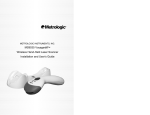
METROLOGIC INSTRUMENTS, INC. ™ MS1633 FocusBT with ® Bluetooth Wireless Technology Area Imaging Bar Code Scanner Installation and User’s Guide Copyright © 2008 by Metrologic Instruments, Inc. All rights reserved. No part of this work may be reproduced, transmitted, or stored in any form or by any means without prior written consent, except by reviewer, who may quote brief passages in a review, or provided for in the Copyright Act of 1976. Trademarks Metrologic is a registered trademark of Metrologic Instruments, Inc. Products identified in this document are hereby acknowledged as trademarks, registered or otherwise, of Metrologic Instruments, Inc. or their respective companies. The Bluetooth word mark and logos are owned by the Bluetooth SIG, Inc. and any use of such marks by Metrologic Instruments, Inc. is under license. Other trademarks and trade names are those of their respective owners. TABLE OF CONTENTS Introduction Product Overview ............................................................................................. 1 Scanner and Accessories................................................................................. 2 Scanner Components....................................................................................... 3 Labels............................................................................................................... 4 Maintenance..................................................................................................... 5 Getting Started Battery Tips and Cautions ................................................................................ 6 Charger Status Indicators................................................................................. 6 Charging the Battery ........................................................................................ 7 Battery Installation............................................................................................ 8 Low Battery Warning ........................................................................................ 8 Removing the Battery for Charging .................................................................. 8 Driver Installation Driver Installation for USB Adapter with Bluetooth Technology........................ 9 Auto Reconnect Driver Setup ......................................................................... 12 FocusBT Connection Configuration................................................................ 14 Establishing Communication via Bluetooth Technology When FocusBT Acts as a Server to Other Devices........................................ 16 When FocusBT Acts as a Client to Other Devices ......................................... 17 When FocusBT is Used with an MS9535 Cradle............................................ 18 Range Gate Mode .......................................................................................... 18 Inventory Mode............................................................................................... 19 Stand Kits Stand Components, MLPN 46-00147............................................................. 20 Hard Mounting the Stand................................................................................ 21 Assembling the Stand .................................................................................... 22 ii TABLE OF CONTENTS Scanner Operation Two Default Modes of Operation.................................................................... 23 Audible Indicators........................................................................................... 24 Visual Indicators ............................................................................................. 25 Failure Modes................................................................................................. 26 Depth of Field by Minimum Bar Code Element Width .................................... 27 IR Activation Range........................................................................................ 28 Troubleshooting Guide ....................................................................................... 29 Design Specifications ......................................................................................... 33 Default Settings – Communication Parameters.................................................. 35 Configuration Modes .......................................................................................... 37 Upgrading the Flash ROM Firmware .................................................................. 38 Limited Warranty ................................................................................................ 39 Regulatory Compliance Safety ............................................................................................................. 40 EMC ............................................................................................................... 41 Patents ............................................................................................................... 43 Index .................................................................................................................. 44 Contact Information and Office Locations........................................................... 46 iii INTRODUCTION Product Overview ® FocusBT™ is an Area Imager enabled with Bluetooth wireless technology that outperforms the competition by integrating advanced features to both hand-held and presentation mode scanning such as FirstFlash® scanning, automatic aim line, object detection and RangeGate® to optimize efficiency and productivity while providing the freedom of mobility. FocusBT has been designed with a removable battery pack for remote charging to decrease down time caused by having a dead battery. Two battery packs are supplied so the user can simultaneously scan while remotely charging the spare battery. The benefits of this feature are 24/7 scanning and increased throughput for all enterprise applications. FocusBT is the industry leader in Area Imaging and the added benefits of Bluetooth technology along with a rich feature set, make it the scanner of choice for 2D wireless applications. FocusBT ™ MS1633 – 5 Interface BT Interface 1.2 Bluetooth technology Profile Supported: SPP (Serial Port Profile) Decoding and functional capability of the unit is restricted through the use of license numbers provided by Metrologic. Units will not support key features such as, but not limited to, the ability to decode PDF, 2D or OCR fonts without the proper licenses. Desired licenses can be specified at the time of sale or call a Metrologic representative for more information. Standard models ship with the ability to read all 1D, PDF and 2D bar codes. OCR fonts are disabled by default and must be specifically requested at an additional cost. 1 INTRODUCTION Scanner and Accessories BASIC KIT Part # Description Qty. MS1633 MS1633 FocusBT Area Imaging Bar Code Scanner 1 70-72018 Li-Ion Battery Pack 2 46-00358 Battery Charger 1 00-05176 USB BT adaptor 1 00-02544 MetroSelect® Single-Line Configuration Guide* 1 00-02281 Supplemental Configuration Guide* 1 46-00374 Software CD 1 00-02280 MS1633 FocusBT Installation and User’s Guide* 1 * Available on the Metrologic website - www.metrologic.com OPTIONAL ACCESSORIES Part # Description AC to DC Power Transformer - 5.2VDC @ 2 A output. 46-46915 120V United States 46-46913 220V-240V Continental European 46-46912 220V-240V United Kingdom 46-46914 220V-240V Australia 46-46911 220V-240V China 00-02001 MS1633 Focus Stand (46-00147) Installation Guide 46-00147 Modular Presentation Stand Other items may be ordered for the specific protocol being used. To order additional items, contact the dealer, distributor or call Metrologic’s Customer Service Department at 1-800-ID-METRO or 1-800-436-3876. 2 www.metrologic.com INTRODUCTION Scanner and Charger Components Figure 1. Scanner and Charger Components Item Description 1 2 3 4 5 6 7 8 9 10 11 12 13 14 Yellow LED White LED Blue LED Speaker Trigger Red Window Power Button Blue Power LED Battery Pack Lock Power Jack Charging Contacts Blue Power LED White Charge LED See Visual Indicators (on page 25) See Visual Indicators (on page 25) See Visual Indicators (on page 25) See Audible Indicators (on page 24) LED Aperture See Charging the Battery (on page 8) See Charging the Battery (on page 7) See Battery Installation (on page 8) See Battery Installation (on page 8) See Battery Installation (on page 8) See Battery Installation (on page 7) See Charger Status Indicators (on page 6) See Charger Status Indicators (on page 6) 3 INTRODUCTION Labels Each scanner has a label located on the underside of the head. This label provides the unit’s model number, date of manufacture, serial number, CE and caution information. The charger, the USB Adapter and the battery also have labels with important safety and compliance information. The following figure provides examples of these labels and their locations. Figure 2. Label Locations and Samples Caution: To maintain compliance with applicable standards, all circuits connected to the scanner must meet the requirements for SELV (Safety Extra Low Voltage) according to EN/IEC 60950-1. To maintain compliance with standard CSA-C22.2 No. 60950-1/UL 60950-1 and norm EN/IEC 60950-1, the power source should meet applicable performance requirements for a limited power source. 4 www.metrologic.com INTRODUCTION Maintenance Smudges and dirt on the unit's window can interfere with the unit's performance. If the window requires cleaning, use only a mild glass cleaner containing no ammonia. When cleaning the window, spray the cleaner onto a lint free, nonabrasive cleaning cloth then gently wipe the window clean. If the unit's case requires cleaning, use a mild cleaning agent that does not contain strong oxidizing chemicals. Strong cleaning agents may discolor or damage the unit's exterior. 5 GETTING STARTED Battery Tips and Cautions Before the FocusBT can be placed in operation the battery pack must be charged for a minimum of 8 hours. After the initial preparation charge of 8 hours, the battery will only require 6 hours to come to a full charge when it gives a Low Battery warning (see page 8). Follow the steps on page 7 to fully charge the battery. Once charged, the unit is able to handle 5400 continuous first pass readings over a period of approximately 9 hours. After 30 seconds of no activity the scanner will go into a sleep mode to conserve battery life. Caution Observe proper precautions when handling batteries. Batteries may leak or explode if improperly handled. Observe the following precautions when handling batteries for use in this product: • Be sure the battery is turned off before replacing the battery. • Be sure the battery is turned off when installed in the charger. • Use only batteries approved for use in this equipment. Do not mix old and new batteries or batteries of different types. • Do not attempt to insert the battery upside down or backwards. • Do not short or disassemble the battery. • Do not expose the battery to flame or excessive heat. • Do not immerse the battery in water or expose it to water. • Do not transport or store with metal objects such as necklaces or hairpins. • Batteries are prone to leakage when fully discharged. To avoid damage to the product, be sure to remove the battery when no charge remains. • When not in use store the battery in a cool dry place. • Discontinue use immediately should you notice any changes in the battery, such as discoloration or deformation. • Please recycle used batteries in accordance with local regulations. Charger Status Indicators There are two status indicators on the front of the charger located under the Metrologic Logo. The following table lists how these indicators will illuminate depending on the status of the charger. CHARGER STATUS Charging Fully Charged Power On Power Off 6 www.metrologic.com BLUE LED (PW) On On On OFF WHITE LED (CH) Blinking Solid OFF OFF GETTING STARTED Charging the Battery Before the FocusBT can be placed in operation for the first time, the battery must be charged for a minimum of 8 hours. After the initial preparation charge of 8 hours, the battery will only require 6 hours to come to a full charge when it gives a Low Battery warning (see page 8). 1. Check the AC input requirements of the power supply to make sure the voltage matches the AC outlet. The outlet should be located near the charger and easily accessible. 2. Plug the power supply into the socket on the back of the charger. Figure 3 A blue PW will illuminate near the Metrologic logo indicating the charger is receiving power. 3. Verify that the battery pack is not ON. The blue power LED on the battery pack should be OFF. Warning! Damage to the battery pack can occur if it is charged while turned ON. 4. Figure 4 Insert the battery pack into the charger as shown in Figure 5. A white CH will start to flash on and off on the charger near the Metrologic logo. If the white CH does not appear, check to make sure the battery pack is seated all the way in the charger with the battery contacts facing the contacts on the charger. 5. Figure 5 When the battery is completely charged the charging indicator (CH) will stop flashing and stay illuminated. Figure 6 7 GETTING STARTED Battery Installation MS1633 FocusBT is a battery powered scanner. Before the FocusBT can be placed in operation for the first time, the battery must be charged for a minimum of 8 hours. To install the battery: 1. Align the tabs of the charged battery pack with the slots on the scanner’s handle 2. Then, slide the battery pack up toward the top of the scanner. There will be a snap when the battery is installed correctly. Figure 7. Steps for Installing the Battery Low Battery Warning When the battery is low the unit will add an additional beep after the good scan beep. The additional beep alerts the user when there is less than 10% of a charge left on the battery. Removing the Battery for Charging In order to charge the battery, it must be disconnected from the scanner. 1. Turn off the battery by pressing the button near the base of the battery. 2. Disengage the lock on end of the scanner handle (see below). 3. Slide the battery pack down away from the head of the scanner. 4. Lift the battery straight off the scanner handle (see below). Figure 8. Steps for Removing the Battery for Charging 8 www.metrologic.com DRIVER INSTALLATION Driver Installation for USB Adapter with Bluetooth Technology 1. Load the included FocusBT CD into the CD-ROM drive on the host/computer. 2. If the CD-ROM does not automatically open, click on the Window’s Start button, choose Run, then click Browse to locate and open the CD-ROM drive. Double-Click on the Metrologic.exe file then click OK. 3. Click on the MetroBT Driver button to begin installation. Figure 9. 4. Choose a Setup Language then click OK. Figure 10. 9 DRIVER INSTALLATION Driver Installation for USB Adapter with Bluetooth Technology 5. At the welcome screen select Next. Figure 11. 6. After reviewing the end user license agreement, select the, “I accept the terms in the license agreement” option then, click Next to continue. Figure 12. 7. Choose Install from the Ready to Install the Program screen. Figure 13. 10 www.metrologic.com DRIVER INSTALLATION Driver Installation for USB Adapter with Bluetooth Technology 8. To continue the installation procedure without showing warnings for unauthorized drivers, select I accept and click OK. Figure 14. 9. Plug the Bluetooth USB Adapter into the host device then click OK to indicate the Bluetooth Adapter has been connected. Figure 15. 10. After the installation completes click on Yes to restart the host device/computer. The host/computer must be rebooted at this time in order for the driver to function properly. Figure 16. 11 DRIVER INSTALLATION Auto Reconnect Driver Setup 1. Load the included FocusBT CD into the CD-ROM drive on the host/computer. 2. If the CD-ROM does not automatically open, click on the Window’s Start button, choose Run, then click Browse to locate and open the CD-ROM drive. Double-Click on the Metrologic.exe file then click OK. 3. Click on the MetroBT Utility button to begin installation. Figure 17. 4. Click OK to continue. Figure 18. 5. Locate the COMReConnect icon on the Windows desktop and double click to open the program. Figure 19. 12 www.metrologic.com DRIVER INSTALLATION Auto Reconnect Driver Setup 6. The Auto Reconnect Utility will automatically start if any of the COM ports with Bluetooth technology are checked. When running, the utility window will look like the figure below. Clicking the “X” in the corner of the window or clicking on the close button will disable the auto-reconnect feature. However, if the Place icon in the taskbar option is checked, the utility will remain active after the window is closed. Figure 20. 13 DRIVER INSTALLATION FocusBT Connection Configuration 1. Double-Click on the Bluetooth icon located on the Windows Start bar in the bottom right corner of the screen. 2. The new connection wizard will automatically start. Figure 21. Power up the FocusBT scanner and allow it to boot completely Three beeps will indicate the scanner is completely booted. Select Express Mode then click Next. Figure 22. 3. A search for Bluetooth wireless technology devices should find the FocusBT. The number(s) next to FocusBT indicate the serial number of the unit(s) found. Select the proper device and click Next to continue. Figure 23. 14 www.metrologic.com DRIVER INSTALLATION FocusBT Connection Configuration 4. The final screen of the New Connection Wizard should indicate the virtual Bluetooth Com port that was setup. This will usually be a high number, as seen in the screen shot below. Remember this COM number for application setup. Click Next to Continue. Figure 24. 5. After the FocusBT has been added to the connection list, right click on the icon and select Connect in order to establish a link via Bluetooth technology between the FocusBT and your computer. The FocusBT should emit a connection tone and/or the blue light on the top of the unit should stop blinking, indicating a connection has been established. Figure 25. 15 ESTABLISHING COMMUNICATION VIA BLUETOOTH TECHNOLOGY Communication via Bluetooth wireless technology must be established between the FocusBT and the host device before the FocusBT can be used for normal operation. In a network with Bluetooth technology, the FocusBT can operate as a server (service-provide mode), or as a client. When FocusBT Acts as a Server to Other Devices with Bluetooth Technology FocusBT’s default is to act as a server to other devices with Bluetooth technology. In this mode, other devices enabled with Bluetooth wireless technology can initiate a connection to the scanner. FocusBT can be configured to always accept incoming connection requests and not require a valid Bluetooth PIN. Alternatively, FocusBT can be configured to require a valid Bluetooth PIN. In this case, the PIN used by a remote device while establishing connection to the FocusBT, must match the one previously stored in FocusBT. *Bluetooth PIN Not Required ³ 1 2 4 3 0 Bluetooth PIN Required 6 ³ 1 2 4 3 1 6 To store a Bluetooth PIN The FocusBT can be configured to store a Bluetooth PIN so that any remote device trying to establish a connection with the scanner, must match the stored PIN before a connection will made. The stored PIN must be numeric and be between 4 to 16 digits long. A PIN that does not satisfy the criteria will not be stored. After scanning the following bar code, the next bar code scanned will be stored and used as the Bluetooth PIN. This feature is used in conjunction with the Bluetooth PIN required feature. Next bar code is Bluetooth PIN ³ 9 9 9 9 1 8 Scanning the Recall Defaults bar code resets the PIN to the default value of 0000. 16 www.metrologic.com ESTABLISHING COMMUNICATION VIA BLUETOOTH TECHNOLOGY When FocusBT Acts as a Client to Other Devices with Bluetooth Technology In the client device mode of operation, the FocusBT initiates the connection via Bluetooth wireless technology. The Bluetooth address of the remote device is required to establish a connection. The remote device must also be configured to accept incoming connections and must support the Bluetooth wireless technology Serial Port (SPP) profile. • If the Bluetooth address of the remote device is headed with FNC3 3 and consists of a 12-digit hex value (e.g. 000CA7000118), scan the address bar code to establish the communication. Sample of a 12-digit Bluetooth Address with FNC3 ³ • 0 0 0 C A 7 0 0 0 1 1 8 If the Bluetooth address of the remote device is not headed with FNC3 but is just a common 12-digit hex value (e.g. 000CA7000118), first scan the Get Bluetooth Address bar code then scan the remote device’s Bluetooth address bar code. Get Bluetooth Address ³ • 0 0 0 C A 7 F F F F F F If the Bluetooth address code of the remote device is set to 000CA7000000, FocusBT will automatically go into server mode and will not attempt to establish an outgoing connection via Bluetooth wireless technology. To return to service mode: Scan the bar code below to change FocusBT from client mode to service mode. *Provide Bluetooth Service ³ 0 0 0 C A 7 0 0 0 0 0 0 17 ESTABLISHING COMMUNICATION VIA BLUETOOTH TECHNOLOGY When FocusBT is Used with an MS9535 Cradle FocusBT can be configured to communicate with an MS9535 cradle but it will require the FocusBT to be configured to use a special communication protocol used by the MS9535 cradle. Scan the Enable MS9535 Cradle Protocol bar code below to enable the special communication protocol. The FocusBT cannot be configured or flash-upgraded via an MS9535 cradle. Communication settings of the cradle cannot be changed by scanning configuration bar codes with the FocusBT. Support for the MS9535 cradle is limited to bar code transmission. Do not forget to disable the MS9535 cradle protocol when the cradle is no longer in use. Enable MS9535 cradle protocol* ³ 1 2 5 5 1 4 *Disable MS9535 cradle protocol ³ 1 2 5 5 0 4 RangeGate® Mode The operation range of the communication via Bluetooth technology is at least 10 meters between the scanner and host system. When FocusBT is out of operation range for Bluetooth technology, the communication link will break and the blue LED will start to flash on the scanner. FocusBT can be configured to store scanned bar codes into the non-volatile memory when the connection for Bluetooth technology is inactive. The scanner will transmit the bar codes and erase them from memory once the connection for Bluetooth technology is re-established. The size of the non-volatile memory is 32768 bytes. Scan the following bar codes to enable or disable Range Gate Mode. 18 Enable Range Gate *Disable Range Gate ³ ³ 1 2 3 7 0 7 www.metrologic.com 1 2 3 7 1 7 ESTABLISHING COMMUNICATION VIA BLUETOOTH TECHNOLOGY Inventory Mode In Inventory mode, there is a quantity field associated with each bar code. Similar to RangeGate mode, the data is stored in the scanner’s non-volatile memory. However, in inventory mode, the data is always stored independent of whether the connection for Bluetooth technology is active or not, and is not uploaded automatically until a special bar code is scanned. For the bar codes associated with this mode, please consult the FocusBT Supplemental Configuration Guide (MLPN 00-02281A). RangeGate and Inventory Mode are mutually-exclusive. If both are enabled, Inventory mode takes priority. 19 STAND KITS Stand Components, MLPN 46-00147 Figure 26. Stand Components 20 Item Description Qty. a. Stand Base Qty. 1 b. Flexible Shaft Qty. 1 c. Flexible Shaft Cover Qty. 1 d. Scanner Cradle Qty. 1 e. ¼" – 20 x 3/8" Flat Head Phillips, 100° Undercut Qty. 2 f. #8 Round Head Wood Screw Qty. 2 www.metrologic.com STAND KITS Hard Mounting the Stand (Optional) Metrologic provides two #8 wood screws for securing the stand base to the counter top. The following figure provides the pilot hole dimensions for securing the stand base. Figure 27. Stand Base Hole Pattern (Not to Scale) 21 STAND KITS Assembling the Stand Figure 28. Assembling the Stand 22 www.metrologic.com SCANNER OPERATION Two Default Modes of Operation* Multi-Trigger Mode, Out-of-Stand 1. The IR detects an object in the IR activation range and automatically turns on linear illumination. 2. Aim the scanner’s line of light over the bar code. 3. Pull the trigger to initiate scanning. The scanner’s light output will start to flash as it attempts to scan the bar code. If the trigger is released the scanner will stop trying to scan. 4. When scanner successfully reads the bar code it will beep once, the white LED will flash and the decoded data will be transmitted to the host. Presentation, In-Stand Figure 29. Multi-Trigger Mode, Out-of-Stand 1. The IR detects an object in the IR activation range and the scanner’s light output automatically starts to flash as it attempts to scan the bar code. 2. The scanner continuously attempts to scan the bar code until either it succeeds or the bar code is removed from the scanner’s field of view. 3. When scanner successfully reads the bar code it will beep once, the white LED will flash and the decoded data will be transmitted to the host. * For additional configurable modes of operation, please refer to the Area Imaging Bar Code Supplemental Configuration Guide (MLPN 00-02281). 23 SCANNER OPERATION Audible Indicators When the FocusBT is in operation, it provides audible feedback. These sounds indicate the status of the scanner. Eight settings are available for the tone of the beep (normal, six alternate tones and no tone). To change the tone, refer to the MetroSelect Single-Line Configuration Guide (MLPN 00-02544) or MetroSet2’s help files. One Beep When the scanner successfully reads a bar code it will beep once and the white LED will turn on indicating data is being transmitted. If the scanner does not beep once and the white light does not turn on, then the bar code has not been successfully read. Short Razzberry Tone This tone is a failure indicator (see Failure Modes on page 26). Long Razzberry Tone This tone is a failure indicator (see Failure Modes on page 26). Three Beeps - At Power Up When FocusBT first receives power it will start an initialization sequence. All LEDs (yellow, white, and blue) will light for approximately two seconds then start to alternately flash. When the scanner has finished initializing the LEDs will stop flashing and the unit will beep three times indicating that the scanner is ready for use. Three Beeps - Configuration Mode When entering configuration mode, the white LED will flash while the scanner simultaneously beeps three times. The white and blue LEDs will continue to flash while in this mode. Upon exiting configuration mode, the scanner will beep three times, and the LEDs will stop flashing. When configured, three beeps can also indicate a communications timeout during normal scanning mode. When using single-code-configuring, the scanner will beep three times: a normal tone followed by a short pause, a high tone and then a low tone. This indicates that the single configuration bar code has successfully configured the scanner. Low Battery Tone When the battery is low the unit will add an additional beep after the good scan beep. The additional beep alerts the user when there is less than 10% of a charge left on the battery. 24 www.metrologic.com SCANNER OPERATION Audible Indicators Low to High Beep This tone indicates the connection via Bluetooth technology has been made. High to Low Beep This tone indicates the connection via Bluetooth technology is disconnected. A Double Razz Tone When the communication link for Bluetooth technology is not active, the scanner will emit a double razz tone and the Blue LED will start to flash. This can occur when the scanner is out of the communication range for Bluetooth technology from the host system and the RangeGate feature is disabled. Visual Indicators The MS1633 has three LED indicators (yellow, white and blue) located on the top of the scanner. When the scanner is on, the flashing or stationary activity of the LEDs indicates the status of the current scan and the scanner. No LEDs are Illuminated The LEDs will not be illuminated if the scanner is not receiving power from the host or transformer. The scanner is in stand-by mode. Present a bar code to the scanner and the blue LED will turn on when the IR detects the object. Figure 30. Steady Yellow The yellow LED is illuminated when the scanner is in the stand. Steady Blue The blue LED is illuminated when the scanner is active and linear illumination is on or when the scanner is attempting to decode a bar code. Steady Blue and Single White Flash When the scanner successfully reads a bar code it will beep once and the white LED will turn on indicating data is being transmitted. If the scanner does not beep once and the white light does not turn on, then the bar code has not been successfully read. 25 SCANNER OPERATION Visual Indicators Steady White When the scanner successfully reads a bar code it will beep once and the white LED will turn on indicating data is being transmitted. After a successful scan, the scanner transmits the data to the host device. Some communication modes require that the host inform the scanner when data is ready to be received. If the host is not ready to accept the information, the scanner’s white LED will remain on until the data can be transmitted. Alternating Flashing of Blue and White This indicates the scanner is in configuration mode. A short razzberry tone indicates that an invalid bar code has been scanned while in this mode. Flashing Blue The blue LED will flash if the trigger is pressed while the scanner is in the in-stand presentation mode. The blue LED will stop flashing after a brief period of time. The operation range of communication for Bluetooth wireless technology is approximately 10 meters between the scanner and host system. If the unit is out of range, the communication link will break, the blue LED will start to flash, and the unit will emit a double razz tone. The blue LED will continue to blink for 30 seconds while the unit is out of rage. If RangeGate or Inventory mode are not enabled, the scanner will enter sleep mode to conserve battery power after 30 seconds. Failure Modes Long Razzberry Tone – During Power Up Failed to initialize or configure the scanner. If the scanner does not respond after reprogramming, return the scanner for repair. Short Razzberry Tone – During Scanning An invalid bar code has been scanned when in configuration mode or the trigger has been pulled too fast. 26 www.metrologic.com SCANNER OPERATION Depth of Field by Minimum Bar Code Element Width MINIMUM BAR CODE ELEMENT WIDTH 1D / PDF A B Data Matrix C D E F G mm .132 .19 .254 .33 .533 .254 .381 mils 5.2 7.5 10.4 13 21 10 15 Figure 31. Depth of Field by Minimum Bar Code Element Width Decoding and functional capability of the unit is restricted through the use of license numbers provided by Metrologic. Units will not support key features such as, but not limited to, the ability to decode PDF, 2D or OCR fonts without the proper licenses. Desired licenses can be specified at the time of sale or call a Metrologic representative for more information. Standard models ship with the ability to read all 1D, PDF and 2D bar codes. OCR fonts are disabled by default and must be specifically requested at an additional cost. Specifications are subject to change without notice. 27 SCANNER OPERATION IR Activation Range The MS1633 has a built in object detection sensor that instantly turns on the scanner when an object is presented within the scanner’s IR activation area. Figure 32. IR Activation Area Specifications are subject to change without notice. 28 www.metrologic.com TROUBLESHOOTING GUIDE The following guide is for reference purposes only. Contact a Metrologic representative at 1-800-ID-Metro or 1-800-436-3876 to preserve the limited warranty terms. All Interfaces MS1633 Series Troubleshooting Guide Symptoms Possible Causes Solution Check to make sure the battery is turned on. No LEDs, beep or illumination. No power is being supplied to the scanner. Check to make sure the battery is properly installed. The battery may need to be charged. Long Razz tone on power up. There has been a diagnostic failure. Contact a Metrologic service representative, if the unit will not function. Long Razz tone when exiting configuration mode. There was a failure saving the new configuration. Re-try to configure the scanner. Contact a Metrologic Service Representative if the unit will not hold the saved configuration. Long Razz tone. There is a scanning mechanism failure. Contact a Metrologic service representative. Short Razz tone in configuration mode. An invalid bar code has been scanned. Scan a valid bar code or quit configuration mode. 29 TROUBLESHOOTING GUIDE Symptoms Possible Causes Solution The unit powers The beeper is up, but does not disabled and no tone beep when bar is selected. code is scanned. Enable the beeper and select a tone. The unit powers up, but does not scan and/or beep. The bar code symbology trying to be scanned is not enabled. UPC/EAN, Code 39, interleaved 2 of 5, Code 93, Code 128, Codabar and PDF are enabled by default. Verify that the type of bar code being read has been selected. The unit powers up, but does not scan and/or beep. The scanner is trying to scan a bar code that does not match the configured criteria. Verify that the bar code being scanned falls into the configured criteria (i.e. character length lock or minimum bar code length settings). The unit scans a bar code, but locks up after the first scan and the white LED stays on. The scanner is configured to support some form of host handshaking but is not receiving the signal. If the scanner is setup to support ACK/NAK, check to make sure the host is supporting the handshaking properly. The unit scans, but the data transmitted to the host is incorrect. The scanner’s data format does not match the host system requirements. Verify that the scanner’s data format matches that required by the host. 30 www.metrologic.com TROUBLESHOOTING GUIDE Symptoms Possible Causes Solution The bar code may have been printed incorrectly. Check if it is a check digit/character/or border problem. The scanner is not configured correctly for this type of bar code. Check if check digits are set properly. The minimum symbol length setting does not work with the bar code. Check if the correct minimum symbol length is set. The unit scans the bar code but there is no data. The configuration is not set correctly. Make sure the scanner is configured for the appropriate mode. The unit scans but the data is not correct. The scanner and host may not be configured for the same interface parameters. Check that the scanner and the host are configured for the same interface parameters. The unit is transmitting each character twice. The configuration is not set correctly. Increase interscan code delay setting. Adjust whether the F0 break is transmitted. It may be necessary to try this in both settings. Alpha characters show as lower case. The computer is in Caps Lock mode. Enable Caps Lock detect setting of the scanner to detect if the PC is operating in Caps Lock. The unit beeps at some bar codes and NOT for others of the same bar code symbology. 31 TROUBLESHOOTING GUIDE Symptoms Possible Causes Everything works except for a couple of characters. These characters may not be supported by that country’s key look up table. Try operating the scanner in Alt mode. The unit powers up OK and scans OK but does not communicate properly with the host. The USB adapter may not be connected properly Check to make sure the USB adapter is connected properly. Characters are being dropped. Inter-character delay needs to be added to the transmitted output. Add some inter-character delay to the transmitted output by using the Configuration Guides (MLPN 00-02544 and 00-02065). 32 www.metrologic.com Solution DESIGN SPECIFICATIONS MS1633 DESIGN SPECIFICATIONS OPERATIONAL Light Source: Pulse Duration: Maximum Output: Depth of Scan Field: Field of View: Minimum Bar Width: Infrared Activation: Motion Tolerance: Decode Capability: Image Transfer*: Print Contrast: Number Characters Read: Beeper Operation: Indicators (LED) Default Settings: LED 645 nm 10 µs to 8000 µs 0.76 mW Peak 0 mm – 330 mm (0" – 13") for 0.330 mm (13 mil) Bar Code at Default Setting 49 mm W x 19 mm H (1.9" W x 0.8" H) at 20 mm (0.8") 264 mm x 106 mm (10.4" W x 4.2" H) at 280 mm (11.0") 0.127 mm (5.0 mil) Long Range: 0 mm – 203 mm (0" – 8") from Window Short Range: 0 mm – 101 mm (0" – 4") from Window 47 cm/sec (18"/sec) 100% UPC in stand Autodiscriminates All Standard 1-D, GS1 Databar, PDF417, microPDF, MaxiCode, Data Matrix, QR Code, UCC, EAN Composites, Postals, Aztec BMP, TIFF, or JPEG output *RS232 and USB only 20% Minimum Reflectance Difference Up to 80 Data Characters on 1D; 1850 Text Characters for PDF417 7 tones or no beep Blue Unit Powered, Ready to Scan White Good Read Yellow In Stand Decoding and functional capability of the unit is restricted through the use of license numbers provided by Metrologic. Units will not support key features such as, but not limited to, the ability to decode PDF, 2D or OCR fonts without the proper licenses. Desired licenses can be specified at the time of sale or call a Metrologic representative for more information. Standard models ship with the ability to read all 1D, PDF and 2D bar codes. OCR fonts are disabled by default and must be specifically requested at an additional cost. Specifications are subject to change without notice. 33 DESIGN SPECIFICATIONS MS1633 DESIGN SPECIFICATIONS MECHANICAL Height: Width: Depth: 183 mm (7.2") Handle 30 mm (1.2") Head 79 mm (3.1") 111 mm (4.9") Weight: 290 g (10.23 oz) Input Voltage: 5.2VDC ± 0.25V ELECTRICAL Peak = 2 W (Typical) Power: Operating = 1.65 W (Typical) Idle / Standby = 800 mW (Typical) Operation = 400 mA (Typical) Current: Idle / Standby = 100 mA (Typical) DC Transformer: Class 2; 5.2VDC @ 2A For regulatory compliance information see pages 40 – 42. ENVIRONMENTAL Operating = 0°C to 40° (32° to 104°F) Temperature: Storage = -20°C to 50°C (-4°F to 122°F) Humidity: Light Levels: Shock: Contaminants: Ventilation: 0% to 95% Relative Humidity, Non-Condensing Up to 190,000 Lux (17,670 Footcandles) Designed to withstand 1.5 m (5') drops Sealed to resist airborne particulate contaminants None required Specifications are subject to change without notice. 34 www.metrologic.com DEFAULT SETTINGS – COMMUNICATION PARAMETERS Many functions of the scanner can be “configured” – that is, enabled or disabled. The scanner is shipped from the factory configured to a set of default conditions. The default parameter of the scanner has an asterisk (*) in the charts on the following pages. If an asterisk is not in the default column then the default setting is OFF or DISABLED. PARAMETER Multi-Try Trigger Out-of-Stand Presentation Mode In-Stand DEFAULT * * PARAMETER Data Matrix QR Code Continuous Trigger Maxicode Single Trigger Aztec Aiming in Trigger and Continuous Modes * Aiming in Presentation Mode Long-Range In-Stand Postals Mod 43 Check on Code 39 * Short-Range In-Stand Long-Range Out-of-Stand DEFAULT MSI-Plessy 10/10 Check Digit MSI-Plessy Mod 10 Check Digit * * Paraf Support ITF Short-Range Out-of-Stand ITF Symbol Lengths Variable RangeGate Mode Symbol Length Lock None Inventory Mode Beeper tone Normal * * Beep/transmit sequence Before transmit Communication timeout None * * Razzberry tone on timeout UPC/EAN Code 128 Code 93 Codabar Interleaved 2 of 5 (ITF) * MOD 10 check on ITF * Full ASCII Code 39 PDF Same symbol rescan timeout: 1000 msecs * Same symbol rescan timeout configurable in 50 msec steps (maximum of 6.35 sec.) Code 11 Code 39 Three beeps on timeout No Same symbol timeout Infinite Same symbol timeout * 35 DEFAULT SETTINGS – COMMUNICATION PARAMETERS PARAMETER Inter-character delay configurable in 1 msec steps (maximum of 255 msecs) DEFAULT 1 msecs 10 msecs in KBW PARAMETER DEFAULT Tab Suffix “DE” Disable Command Number of scan buffers (maximum) 8 Enable Command Transmit UPC-A check digit * ACK/NAK Transmit UPC-E check digit Two Digit Supplements Expand UPC-E Five Digit Supplements Convert UPC-A to EAN-13 Bookland Transmit lead zero on UPC-E 977 (2 digit) Supplemental Requirement Transmit UPC-A number system * Supplements are not Required * Transmit UPC-A Manufacturer ID# * Two Digit Redundancy * Transmit UPC-A Item ID# * Five Digit Redundancy Transmit Codabar Start/Stop Characters Coupon Code 128 CLSI Editing (Enable) † Configurable Code Lengths 7 avail Transmit Mod 43 Check digit on Code 39 † Code Selects with configurable Code Length Locks 3 avail Transmit Mod 10/ITF Configurable Prefix characters 10 avail Transmit MSI-Plessy Suffix characters 10 avail Transmit Sanyo ID Characters Prefixes for Individual Code types Nixdorf ID Editing LRC Enabled Function/Control Key Support UPC Prefix Omnidirectional Scanning UPC Suffix Linear Only Scanning Carriage Return * * * Linear 1D / Omni 2D Tab Prefix † These options are mutually exclusive. One can not be used in conjunction with the other. 36 www.metrologic.com CONFIGURATION MODES The MS1633 FocusBT Series has three modes of configuration. • Bar Codes The MS1633 can be configured by scanning the bar codes included in the Metrologic Single-Line Configuration Guide (MLPN 00-02544). This manual can be downloaded for FREE from Metrologic’s website (www.metrologic.com). • MetroSet2 This user-friendly Windows-based configuration program allows you to simply ‘point-and-click’ at the desired scanner options. This program can be downloaded for FREE from Metrologic’s website (www.metrologic.com) or set-up disks can be ordered by calling 1-800-ID-METRO. • Serial Configuration This mode of configuration is ideal for OEM applications. This mode gives the end-user the ability to send a series of commands using the serial port of the host system. The commands are equivalent to the numerical values of the bar codes located in the MetroSelect Single-Line Configuration Guide (MLPN 00-02544). 37 UPGRADING THE FLASH ROM FIRMWARE The MS1633 FocusBT is part of Metrologic's line of scanners with flash upgradeable firmware. The upgrade process requires a new firmware file supplied to the customer by a customer service representative and Metrologic's MetroSet2 software. A personal computer running Windows 2000 or greater with an available USB port is also required to complete the upgrade. FocusBT can only be upgraded via USB using a Bluetooth USB Adapter dongle (MLPN 00-05176) and software CD (MLPN 46-00374). The dongle is used to emulate a serial port on the host PC that FocusBT can connect to. The dongle and associated drivers must be installed on the host PC prior to the flash upgrade process. To upgrade the firmware in the MS1633: 1. Connect the USB Dongle to an available port on the host PC and establish a connection via Bluetooth technology to the scanner. When the scanner is successfully connected it will beep once and the blue LED will stop blinking. 2. Start the MetroSet2 software. 3. Click on the plus sign (+) next to POS Scanners to expand the supported scanner list. 4. Choose the FocusBT from the list. 5. Click on the Configure FocusBT Scanner button. 6. Select the COM port that the scanner is connected to on the host system. 7. Choose Flash Utility from the options list located on the left side of the screen. 8. Click on the Open File button in the Flash Utility window. 9. Locate and open the flash upgrade file supplied by Metrologic. 10. Click on the Flash Scanner button to begin the flash upgrade. 11. When the upgrade is complete, a “Scanner updated successfully” message will appear in the Flash Utility window. The scanner will reboot. 38 Metrologic's customer service department can be reached at 1-800-ID-METRO or 1-800-436-3876. MetroSet2 is available for download, at no additional cost, from http://www.metrologic.com/corporate/download. www.metrologic.com LIMITED WARRANTY The MS1633 FocusBT ™ scanners are manufactured by Metrologic at its Suzhou, China facility. The MS1633 FocusBT scanners have a two (2) year limited warranty from the date of manufacture and the MS1633 FocusBT battery packs have a one (1) year limited warranty from the date of manufacture. Metrologic warrants and represents that all MS1633 FocusBT scanners are free of all defects in material, workmanship and design, and have been produced and labeled in compliance with all applicable U.S. Federal, state and local laws, regulations and ordinances pertaining to their production and labeling. This warranty is limited to repair, replacement of product or refund of product price at the sole discretion of Metrologic. Faulty equipment must be returned to one of the following Metrologic repair facilities: Blackwood, New Jersey, USA; Madrid, Spain; or Suzhou, China. To do this, contact the appropriate Metrologic Customer Service/Repair Department to obtain a Returned Material Authorization (RMA) number. In the event that it is determined the equipment failure is covered under this warranty, Metrologic shall, at its sole option, repair the Product or replace the Product with a functionally equivalent unit and return such repaired or replaced Product without charge for service or return freight, whether distributor, dealer/reseller, or retail consumer, or refund an amount equal to the original purchase price. This limited warranty does not extend to any Product which, in the sole judgment of Metrologic, has been subjected to abuse, misuse, neglect, improper installation, or accident, nor any damage due to use or misuse produced from integration of the Product into any mechanical, electrical or computer system. The warranty is void if: (i) the case of Product is opened by anyone other than Metrologic’s repair department or authorized repair centers; or (ii) any software is installed on the Product other than a software program approved by Metrologic. THIS LIMITED WARRANTY, EXCEPT AS TO TITLE, IS IN LIEU OF ALL OTHER WARRANTIES OR GUARANTEES, EITHER EXPRESS OR IMPLIED, AND SPECIFICALLY EXCLUDES, WITHOUT LIMITATION, WARRANTIES OF MERCHANTABILITY AND FITNESS FOR A PARTICULAR PURPOSE UNDER THE UNIFORM COMMERCIAL CODE, OR ARISING OUT OF CUSTOM OR CONDUCT. THE RIGHTS AND REMEDIES PROVIDED HEREIN ARE EXCLUSIVE AND IN LIEU OF ANY OTHER RIGHTS OR REMEDIES. IN NO EVENT SHALL METROLOGIC BE LIABLE FOR ANY INDIRECT OR CONSEQUENTIAL DAMAGES, INCIDENTAL DAMAGES, DAMAGES TO PERSON OR PROPERTY, OR EFFECT ON BUSINESS OR PROPERTY, OR OTHER DAMAGES OR EXPENSES DUE DIRECTLY OR INDIRECTLY TO THE PRODUCT, EXCEPT AS STATED IN THIS WARRANTY. IN NO EVENT SHALL ANY LIABILITY OF METROLOGIC EXCEED THE ACTUAL AMOUNT PAID TO METROLOGIC FOR THE PRODUCT. METROLOGIC RESERVES THE RIGHT TO MAKE ANY CHANGES TO THE PRODUCT DESCRIBED HEREIN. CORPORATE HEADQUARTERS, NORTH AMERICA METROLOGIC EUROPEAN REPAIR CENTER (MERC) Metrologic Instruments, Inc. 90 Coles Rd. Blackwood, NJ 08012-4683 Customer Service Department Tel: 1-800-ID-METRO Fax: 856-228-6673 Email: [email protected] Metrologic Eria Ibérica, SL C/Alfonso Gomez, 38-40, 1D 28037 Madrid Tel: +34 913 751 249 Fax: +34 913 270 437 MTLG AUTO ID INSTRUMENTS (SHANGHAI) CO., LTD Suzhou Sales Office BLK A, Room# 03/03-04 No.5 Xinghan Street, Xinsu Industrial Square China-Singapore Suahou Industrial Park, Suzhou, PRC Tel: 86-512-67622550 Fax: 86-512-67622560 Email: [email protected] 39 REGULATORY COMPLIANCE Safety ITE Equipment IEC 60950-1, EN 60950-1 LED Class 1 LED Product: IEC 60825-1:1993+A1+A2, EN 60825-1:1994+A1+A2 Caution Use of controls or adjustments or performance of procedures other than those specified herein may result in hazardous radiation exposure. Under no circumstances should the customer attempt to service the LED scanner. Never attempt to look at the LED beam, even if the scanner appears to be nonfunctional. Never open the scanner in an attempt to look into the device. Doing so could result in hazardous radiation exposure. The use of optical instruments with the LED equipment will increase eye hazard. Atención La modificación de los procedimientos, o la utilización de controles o ajustes distintos de los especificados aquí, pueden provocar una exposición de luz brillante peligrosa. Bajo ninguna circunstancia el usuario deberá realizar el mantenimiento del LED (Diodo Emisor de Luz) del lector. Ni intentar mirar al haz del LED incluso cuando este no esté operativo. Tampoco deberá abrir el lector para examinar el aparato. El hacerlo puede conllevar una exposición peligrosa a la luz del LED. El uso de instrumentos ópticos con el equipo LED puede incrementar el riesgo para la vista. Attention L'emploi de commandes, réglages ou procédés autres que ceux décrits ici peut entraîner de graves irradiations. Le client ne doit en aucun cas essayer d'entretenir lui-même le scanner ou la LED. Ne regardez jamais directement le rayon LED, même si vous croyez que le scanner est inactif. N'ouvrez jamais le scanner pour regarder dans l'appareil. Ce faisant, vous vous exposez à un risque d’irradiation. L'emploi d'appareils optiques avec cet équipement à LED augmente le risque d'endommagement de la vision. Achtung Die Verwendung anderer als der hier beschriebenen Steuerungen, Einstellungen oder Verfahren kann eine gefährliche Licht emittierender Dioden strahlung hervorrufen. Der Kunde sollte unter keinen Umständen versuchen, den Licht emittierender Dioden-Scanner selbst zu warten. Sehen Sie niemals in den Licht emittierender Diodenstrahl, selbst wenn Sie glauben, daß der Scanner nicht aktiv ist. Öffnen Sie niemals den Scanner, um in das Gerät hineinzusehen. Wenn Sie dies tun, können Sie sich einer gefährlichen Licht emittierender Diodenstrahlung aussetzen. Der Einsatz optischer Geräte mit dieser Laserausrüstung erhöht das Risiko einer Sehschädigung. Attenzione L'utilizzo di sistemi di controllo, di regolazioni o di procedimenti diversi da quelli descritti nel presente Manuale può provocare delle rischiose esposizioni radiattive. Il cliente non deve assolutamente tentare di riparare egli stesso lo scanner LED (o diodo emettitore di luce). Non guardate mai il raggio LED (d. emettitore di luce), anche se credete che lo scanner non sia attivo. Non aprite mai lo scanner per guardare dentro l'apparecchio. Facendolo potete esporVi ad una radiazione rischiosa. L'uso di apparecchi ottici, equipaggiati con raggi LED (d. emettitori di luce), aumenta il rischio di danni alla vista. 40 www.metrologic.com REGULATORY COMPLIANCE EMC Emissions FCC Part 15, ICES-003, CISPR 22, EN 55022, EN300 328 V1.6.1, EN301 489-17 V1.2.1 Immunity CISPR 24, EN 55024 Changes or modifications not expressly approved by the party responsible for compliance could void the user’s authority to operate the equipment. Class B Devices This device complies with Part 15 of the FCC Rules. Operation is subject to the following two conditions: (1) This device may not cause harmful interference, and (2) this device must accept any interference received, including interference that may cause undesired operation. This equipment has been tested and found to comply with the limits for a Class B digital device, pursuant to Part 15 of the FCC rules. These limits are designed to provide reasonable protection against harmful interference in a residential installation. This equipment generates, uses and can radiate radio frequency energy and, if not installed and used in accordance with the instructions, may cause harmful interference to radio communications. However, there is no guarantee that interference will not occur in a particular installation. If this equipment does cause harmful interference to radio or television reception, which can be determined by turning the equipment off and on, the user is encouraged to try to correct the interference by one or more of the following measures: • Reorient or relocate the receiving antenna • Increase the separation between the equipment and receiver • Connect the equipment into an outlet on a circuit different from that to which the receiver is connected • Consult the dealer or an experienced radio/TV technician for help Notice This Class B digital apparatus complies with Canadian ICES-003. Remarque Cet appareil numérique de classe B est conforme à la norme canadienne NMB-003. 41 REGULATORY COMPLIANCE Exposure to Radio Frequency Energy The radiated output power of this intentional wireless radio is far below the FCC radio frequency exposure limits. The internal wireless radio operates within guidelines found in radio frequency safety standards and recommendations, which reflect the consensus of the scientific community. The level of energy emitted is far less than the electromagnetic energy emitted by wireless devices such as mobile phones. However, the use of wireless radios may be restricted in some situations or environments, such as aboard airplanes. If you are unsure of restrictions, you are encouraged to ask for authorization before turning on the wireless radio. For more information from the US FCC about exposure to RF energy, see: www.fcc.gov/oet/rfsafety For information about the scientific research related to RF energy exposure, see the EMF Research Database maintained by the World Health Organization at: www.who.int/emf 42 www.metrologic.com PATENTS For patent information, please refer to www.honeywellaidc.com/patents. 43 INDEX A AC ...........................................2, 38 Accessories ...................................2 Adapter.............................. 2, 10–12 Address .......................................18 Aperture.........................................3 Audible Indicator....................27–28 B Bar Code ................... 33–36, 37, 41 Bar Code Element .......................30 Battery .......................................6–9 Beep ........ 9, 27–28, 33–36, 37, see indicators Blue LED ................. 3, 6, 27–28, 43 C Cable Communication........................43 Caution ..................................46–48 CE .................................................4 Charge.......................... See Battery Class ...........................................47 Client ...........................................18 Communication Parameters ..39–40 Compliance ..................... 44, 46–48 Configuration ... 2, 15–16, 33–36, 41 Cradle..........................................20 Current ........................................38 Customer Service....................2, 44 FirstFlash ...................................... 1 Flash ROM.................................. 43 I Indicator Audible .......... 3, 9, 27–28, 37, 43 Failure ........................... 3, 27–28 Visual ............ 3, 6, 27–28, 37, 43 Inventory ..................................... 21 IR ...................................... 1, 25, 32 L Labels ........................................... 4 LED..................... 33–36, 37, 46–48 Blue ............................... 6, 27–28 White ............................. 6, 27–28 Yellow................................ 27–28 Light Levels................................. 38 Light Source................................ 37 M Maintenance ................................. 5 Meteor......................................... 41 MetroSelect........................... 26, 41 MetroSet2 ................................... 41 Mode of Operation ...................... 25 N Notices ........................................ 47 D P DC ...........................................2, 38 Decode ........................................37 Default Parameters ...............39–40 Depth of Field ..............................30 Driver.....................................10–16 Patent ......................................... 49 Pin............................................... 17 Power.............................. 38, 41, 43 Presentation................................ 25 Product Safety ...................... 46–48 E R EMC ............................................38 Radio Frequency......................... 48 RangeGate.............................. 1, 20 Razz.......................... 27–28, 33–36 Reconnect............................. 13–14 Repair ......................................... 44 RMA............................................ 44 F Firmware .....................................43 44 www.metrologic.com INDEX S U Server..........................................16 Service ........................................39 Specifications Electrical ..................................34 Environmental..........................34 Mechanical...............................33 Operational ..............................33 Stand ............... 2, 20–22, 20–22, 23 UL ................................................. 4 Upgrade ...................................... 38 Utility ..................................... 12–13 T Tone ......................................25–26 Alternate ..................................24 Transformer.............................2, 34 Trigger ...........................................3 Troubleshooting.....................29–32 V Ventilation ................................... 34 Visual Indicator ..................... 25–26 Voltage........................................ 34 W Warranty ..................................... 39 White LED..................... 3, 6, 25–26 Window ..................................... 3, 5 Y Yellow LED ....................... 3, 25–26 45 46 www.metrologic.com September 2008 00 - 02280E