1
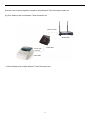
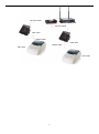
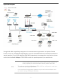
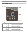
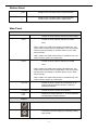
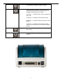
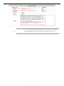
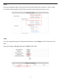
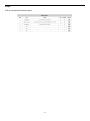
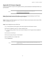
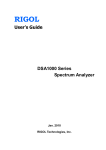
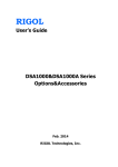
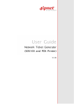
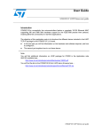
LevelOne DSA-1000 / PRT-1000 Device Server / Thermal Printer User Manual V1.0 TABLE OF CONTENTS 1. INTRODUCTION ...................................................................................................................................................................... - 3 2. DEVICE OVERVIEW ............................................................................................................................................................... - 7 3. HARDWARE SETUP ............................................................................................................................................................ - 10 4. SYSTEM CONFIGURATION ............................................................................................................................................... - 12 - , All trademarks and trade names are the properties of their respective owners. 1. Introduction Overview of Network Ticket Generator Whether you are “operating a wireless hotspot service for generating revenue” or “providing free but controlled wireless internet access to guests”, it would be handy to both the operators and the wireless users if the account information (such as username, password, SSID and etc.) can be readily output to Thermal Printers and printed out as account tickets. DSA-1000 is designed specifically to operate in conjunction with specific Controllers/Gateways. Typical serial Thermal Printers on the market today may or may not be IP network ready, and it is not practical to integrate each brand one-by-one with Controllers/Gateways. Hence, it has specifically designed a smart device server - DSA-1000, for two purposes: 1. Attaching before a serial Thermal Printer so that one or more Thermal Printers can be connected to a Controller/Gateway via IP networks. 2. Pre-integrated with the Controller/Gateway so that account generation becomes quick and easy to the operator, simply by a push of buttons on the device. It provides DSA-1000 and a Thermal Printer as a combo set called Network Ticket Generator. The followings are typical application scenarios: A small business who wishes to quickly set up a wireless service hotspot for charged internet service may purchase a Gateway, and a Network Ticket Generators set. The Gateway alone serves as an AP and a gateway, Network Ticket Generator enables the registration operator to generate and issue accounts via push buttons on the DSA-1000 and hand out the account ticket printed out by Thermal Printer. A corporate has several sites. Deployed at the reception area of each site are with a DSA-1000 and a Thermal Printer. Guests who need wireless connection to the internet simply need to request the receptionist and obtain a slip with account information. The guest account will automatically expire after the pre-configured time. A hotel has a Controller/Gateway and multiple APs within it’s hospitality areas. Multiple sets of Network Ticket Generator are distributed at the service desks and lounge counters. The service clerks are able to create accounts for their guests with charged or free internet service depending on the hotel’s service model. -3- Below are two network diagrams examples using Network Ticket Generator combo set. 1) One Gateway with one Network Ticket Generator set Ethernet Cable WHG-1000 DSA-1000 RS232 Cable PRT-1000 2) One Gateway with multiple Network Ticket-Generator sets -4- Ethernet Cable WHG-1000 Ethernet Cable DSA-1000 RS232 Cable DSA-1000 RS232 Cable PRT-1000 PRT-1000 -5- Application Diagram DSA-1000 DSA-1000 PRT-1000 PRT-1000 Though DSA-1000 is specifically designed to for on-demand account generation and operate Thermal Printers, it can also be deployed independently to connect other RS232 devices to an Ethernet network for remote operation. If you will be deploying DSA-1000 independently to manage other serial devices, please carefully set the Serial Settings in DSA-1000 to match the operating needs of your serial device. If you connect other serial device to DSA-1000 and are unable to remotely operate your connected serial device, please check that: Note: The settings under Serial Settings of DSA-1000 are configured to match your serial device operating requirements. If your serial device application operates on pure serial communication then you need to setup a COM port redirector. -6- 2. Device Overview Panel Overview Top Panel Adapter Socket (12V/1A) The power socket for connecting to an external power source through the power adapter provided in the package. DC Socket (DC12V) The power socket for connecting to an external power source through a DC power supply. Restart Button Press to restart DSA-1000. Ethernet Port Ethernet port for connecting to a Controller/Gateway. -7- Bottom Panel COM 1 Serial Port for connection with a Thermal Printer. COM 2 Serial Port for connection with a Thermal Printer. Used for back up when COM 1 malfunctions. Main Panel LED indicators Power Turned on when properly connect to power supply. COM 1 Turned on when output is switched to COM1. Note: COM 2 When COM 1 and COM 2 are blinking simultaneously, this means that Terminal Server configuration is not set correctly. Please check the settings in Terminal Server of your Gateway/Controller. When COM 1 and COM 2 are turned on simultaneously, this means that the system is in safe mode. Turned on when output is switched to COM2. Note: When COM 1 and COM 2 are blinking simultaneously, this means that Terminal Server configuration is not set correctly. Please check the settings in Terminal Server of your Gateway/Controller. When COM 1 and COM 2 are turned on simultaneously, this means that the system is in safe mode. Link / Act Turned on when LAN port is connected to an upstream networking device such as a switch or Gateway/Controller. 100 Mbps Turned on when LAN port is connected. 7 Segment Displays an integer between 0 ~ 9 which indicates the billing plan number selected. Buttons For future use. Increase the numeric display for selecting a billing plan number. -8- For switching the output to COM1 or COM2. Press this button followed by selecting a number and press Enter will perform a specific action. The available combinations are as follows: FUNTION + 1 + ENTER: Print out the IP address of DSA-1000. FUNTION + 8 + ENTER: Enter panel test mode. FUNTION + 9 + ENTER: Reset DSA-1000 to factory default. FUNTION + 0 + ENTER: Lock the panel of DSA1000. To Unlock select your lock number and press ENTER Decrease the numeric display for selecting a billing plan number. Create and print out an account for the chosen billing plan. -9- 3. Hardware Setup The following diagram illustrates how to connect DSA-1000 to the Thermal Printer and Gateways/Controllers. Please follow the steps described below to install hardware: Ethernet Cable WHG-1000 DSA-1000 RS232 Cable PRT-1000 1. Attach DSA-1000 to a power source, either through adaptors provided in the package or through DC socket with a DC power supply. 2. Attach Thermal Printer to a power source, through adaptors provided in the package and turn on the power switch situated on the left side of the device. 3. Connect Thermal Printer to the COM1 port of DSA-1000 by a RS-232 cable provided within Thermal Printer package. 4. Connect DSA-1000 to the LAN port of your Gateway/Controller by an Ethernet cable. Note: You need to connect to the correct LAN port if your Gateway/Controller is operating in Port-based mode. 5. To verify that the system is up and running, enter the WMI of your Gateway/Controller and ping DSA1000 (192.168.1.10). You should see replies from DSA-1000 as shown below, this means that the devices are setup and working properly. - 10 - Note: If you are unable to get a reply from pinging DSA-1000, please refer to System Configuration and check that the network settings of DSA-1000 and Gateway/Controller interface connected to are under the same subnet. - 11 - 4. System Configuration DSA-1000 is designed specifically to operate in conjunction with all Gateways/Controllers. If you are not using default settings, before connecting DSA-1000 to your Gateway/Controller, some configurations steps are required. The configuration instructions for Gateways/Controllers and DSA-1000 are covered in the following sections. 4.1 DSA-1000 DSA-1000 supports web based configuration. By factory default, DSA-1000 web interface can be accessed with IP address: 192.168.1.10 Subnet Mask: 255.255.255.0 Default Gateway: 192.168.1.254 Step1: Configure administrator PC’s TCP/IP settings with a static IP address that is under the same subnet mask as DSA-1000. For example: 192.168.1.20 - 12 - Step2: Attach DSA-1000 to a power supply using the adapter provided in the package. Connect the administrator PC to the Ethernet Port of DSA-1000 via an Ethernet cable. Launch a web browser and type in the default IP address of DSA-1000 in the address field (http://192.168.1.10), the web interface of DSA-1000 should appear. Step3: Change DSA-1000 Network Settings if necessary so that the IP address of DSA-1000 is under the same subnet as the Gateway/Controller’s interface, which DSA-1000 will be connected to. Click Apply to save the settings. - 13 - 4.2 Gateway/Controller Configuration procedures are similar on all Gateway/Controller models, the following instruction steps uses WHG-1000 as illustration. Note: the screenshots may be slightly different for your Gateway/Controller model. Step1: Connect administrator PC to your Gateway/Controller and access the WMI (web management interface). - 14 - Step2: Enter the configuration page of the Service Zone which DSA-1000 will be connected to. Check to make sure that the network settings of DSA-1000 are under the same subnet as this service zone. Step3: Go to the configuration page for On-demand authentication; click Configure to edit Terminal Server settings. Enter the IP address (192.168.1.10) and Port (5000) of DSA-1000. - 15 - Step4: Edit and enable desired billing plans. - 16 - 5. Operation Instructions After completing the Hardware Setup and the devices are physically connected, the system is ready for operation. This section will describe how to operate DSA-1000 to printout tickets for enabled billing plans. 1. Select an enabled billing plan number on DSA-1000 by or button. The numeric LED dis- play on the center of the device represents the billing plan number currently selected. Press button on DSA-1000 to create and print out an on-demand account of the selected billing plan. THERMAL PRINTER will print out the ticket with the text format (Without background image) configured on your Gateway/Controller in Ticket Customization. Note: If you are unable to get a ticket printout after pressing ENTER, please check if the selected plan is enabled. - 17 - Appendix A. DSA-1000 Web Interface Summary The attribute setting in this web interface is for COM 1 only. COM 2 uses default settings that are unchangeable. Serial Settings (corresponding to Thermal Printer) Data Baud Rate Select the desired baud rate. (The number of characters per second transferred) Data Bits Select the number of bits in each character. Data Parity Choose between Even or Odd for error detection, or select None for no error detection. Stop Bits Choose the number of stop bits to be sent at the end of every character. Electronic devices usually use 1 bit, slower electromechanical devices use 1.5 bit. Flow Control Choose the method of flow control to pause and resume the transmission of data to coordinate with printer speed. Select None if flow control is not required. Appendix E - Command Line Interface Network Settings Static IP Address The static IP address assigned to DSA1000. Static Subnet Mask The subnet mask of DSA-1000. Static Default Gateway The default gateway of DSA-1000. Static DNS Server Set the DNS server used by DSA-1000. Transmit Timer TCP transmit timer, set the desired value or use default value. When the timer expires for a sent packet, sender will retransmit the packet. Server Listening Port Set the port number for communication with the Gateway/Controller. Lock Password This attribute is the integer between 0 ~ 9 that will be set as the password for unlocking the main panel. Utilities Firmware Upgrade Firmware of DSA-1000 can be upgraded by clicking the Apply button. Note: Upgrade preparations are required before upgrade, please refer to Appendix B. Firmware Upgrade Restart Click Apply to restart DSA-1000 device. Reset to Factory Default Click Apply to reset DSA-1000 to factory default settings. Status Software Version The current software version running on DSA-1000. 19 Appendix E - Command Line Interface Appendix B. Firmware Upgrade Software tools tftpd32 is required in the upgrade procedure, please download and install tftpd32 before you proceed further. Note: Tftpd32 can be downloaded from the following link: http://tftpd32.jounin.net/tftpd32.html Step1: Place the new firmware of DSA-1000 on a local location (for example desktop) in the PC that is accessing DSA-1000’s web interface and performing the upgrade. Step2: Configure the TCP/IP settings of your PC with an IP address under the same subnet mask as DSA1000. For example 192.168.1.20 Step3: Launch tftpd32 and click the DHCP tab. 1. In “Current Directory” field, browse for the location path where the firmware is stored. 2. Enter the IP address of your PC in “Server interfaces” field. 3. In “IP pool starting address” field, enter the start IP address of an IP segment that is available for allocation. 4. Set the size of the IP pool. 5. Enter the firmware filename in “Boot file field”. 6. Enter 255.255.0.0 in the “Mask” field. 7. Click Save button. Note: Please make sure that the location path and the firmware for upgrade is correct. 20 Appendix E - Command Line Interface Step4: Click Apply of Firmware Upgrade in DSA-1000’s web interface. DSA-1000 will automatically restart and connect to tftpd32 server set in Step3 as a DHCP client, download the firmware and perform the upgrade. Progress can be observed on tftpd32. Step5: When complete, check the information displayed at Software Version, DSA-1000 have successfully upgraded to the new firmware. 21