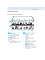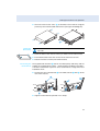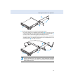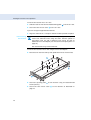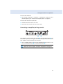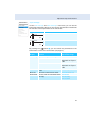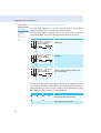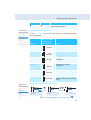
1
Contents
Contents
Important safety instructions .................................................................................................................. 2
The EM 500 G3 rack-mount receiver ....................................................................................................... 5
Areas of application ............................................................................................................................... 5
The frequency bank system ................................................................................................................. 6
Delivery includes .......................................................................................................................................... 8
Product overview ......................................................................................................................................... 9
Overview of the EM 500 G3 receiver .................................................................................................. 9
Overview of the displays .................................................................................................................... 10
Putting the receiver into operation ...................................................................................................... 12
Preparing the receiver for use ........................................................................................................... 12
Connecting an amplifier/mixing console ......................................................................................... 17
Connecting receivers in a network ................................................................................................... 18
Connecting the mains unit ................................................................................................................. 20
Using the receiver ...................................................................................................................................... 21
Switching the receiver on/off ............................................................................................................ 21
Monitoring the audio signal via headphones ................................................................................. 22
Synchronizing a transmitter with the receiver .............................................................................. 23
Deactivating the lock mode temporarily ......................................................................................... 24
Muting the audio signal ...................................................................................................................... 25
Selecting a standard display .............................................................................................................. 26
Using the operating menu ...................................................................................................................... 27
The buttons ........................................................................................................................................... 27
Overview of the operating menu ...................................................................................................... 28
Working with the operating menu ................................................................................................... 30
Adjustment tips and functions .............................................................................................................. 32
Standard displays with additional functions ................................................................................. 32
The main menu “Menu” ...................................................................................................................... 35
The extended menu “Advanced Menu” .......................................................................................... 40
Synchronizing transmitters with receivers ......................................................................................... 46
Synchronizing a transmitter with the receiver – individual operation ..................................... 46
Synchronizing transmitters with receivers – multi-channel operation .................................... 47
Cleaning the receiver ................................................................................................................................ 50
Recommendations and tips .................................................................................................................... 51
If a problem occurs ... ................................................................................................................................ 52
Accessories and spare parts .................................................................................................................... 54
Specifications ............................................................................................................................................. 56
Manufacturer Declarations ..................................................................................................................... 59
Index ............................................................................................................................................................. 61
An animated instruction manual can be viewed on the EM 500 G3 product page on
our website at www.sennheiser.com.
1
Important safety instructions
Important safety instructions
2
•
Read this instruction manual.
•
Keep this instruction manual. Always include this instruction manual
when passing the product on to third parties.
•
Heed all warnings and follow all instructions in this instruction manual.
•
Only clean the product when it is not connected to the mains. Use a
cloth for cleaning.
•
Refer all servicing to qualified service personnel.
Servicing is required if the product has been damaged in any way,
liquid has been spilled, objects have fallen inside, the product has been
exposed to rain or moisture, does not operate properly or has been
dropped.
•
WARNING: To reduce the risk of short circuits, do not use the product
near water and do not expose it to rain or moisture. Do not place
objects filled with liquids, such as vases or coffee cups, on the product.
•
Only use the supplied mains unit.
•
Unplug the mains unit from the wall socket
– to completely disconnect the product from the mains,
– during lightning storms or
– when unused for long periods of time.
•
Only operate the mains unit from the type of power source specified in
the chapter “Specifications” (see page 55).
•
Ensure that the mains unit is
– in a safe operating condition and easily accessible,
– properly plugged into the wall socket,
– only operated within the permissible temperature range,
– not covered or exposed to direct sunlight for longer periods of time
in order to prevent heat accumulation (see “Specifications” on
page 55).
•
Do not block any ventilation openings. Install the product in accordance
with the instructions given in this instruction manual.
•
Do not install the product near any heat sources such as radiators,
stoves, or other devices (including amplifiers) that produce heat.
•
Only use attachments/accessories specified by Sennheiser.
Important safety instructions
Overloading
Do not overload wall outlets and extension cables as this may result in fire
and electric shock.
Replacement parts
When replacement parts are required, be sure the service technician uses
replacement parts specified by Sennheiser or those having the same
characteristics as the original part. Unauthorized substitutions may result
in fire, electric shock, or other hazards.
Danger due to high volumes
This product is capable of producing sound pressure exceeding 85 dB(A).
85 dB(A) is the sound pressure corresponding to the maximum permissible volume which is by law (in some countries) allowed to affect your
hearing for the duration of a working day. It is used as a basis according to
the specifications of industrial medicine. Higher volumes or longer durations can damage your hearing. At higher volumes, the duration must be
shortened in order to prevent hearing damage. The following are sure
signs that you have been subjected to excessive noise for too long a time:
•
You can hear ringing or whistling sounds in your ears.
•
You have the impression (even for a short time only) that you can no
longer hear high notes.
3
Important safety instructions
Intended use
Intended use of the ew 500 G3 series products includes:
•
having read these instructions especially the chapter “Important
safety instructions”,
•
using the products within the operating conditions and limitations
described in this instruction manual.
“Improper use” means using the products other than as described in this
instruction manual, or under operating conditions which differ from those
described herein.
4
The EM 500 G3 rack-mount receiver
The EM 500 G3 rack-mount receiver
This receiver is part of the evolution wireless series generation 3 (ew G3).
With this series, Sennheiser offers high-quality state-of-the-art RF transmission systems with a high level of operational reliability and ease of use.
Transmitters and receivers permit wireless transmission with studioquality sound.
Features of the evolution wireless 500 G3 series:
•
Optimized PLL synthesizer and microprocessor technology
•
HDX noise reduction system
•
Pilot tone squelch control
•
True diversity technology
•
Switching bandwidth of 42 MHz
•
Safe configuration of a multi-channel system via a network
•
Scan function (Easy Setup) for scanning the frequency banks for
unused channels
Areas of application
The receiver can be combined with the following optional components of
the ew G3 series (see “Accessories and spare parts” on page 53):
Receiver
Transmitters
Combinable with
EM 500 G3
SK 500 G3
•
Clip-on microphones:
ME 2, ME 4, MKE 2, MKE 40
•
Headmics:
ME 3, HSP 2, HSP 4
•
Instrument cable:
CI 1
SKM 500 G3
PEAK
40
30
20
10
RF
0
-10
-20
-30
-40
AF
B.Ch: 20.30
•
MMD 835-1, MMD 845-1
•
MMD 935-1, MMD 945-1
•
MME 865-1, MMK 965-1
ew500 G3
542.625 MHz
EQ
P + 12dB
Interchangeable microphone heads:
SKM500
5
The EM 500 G3 rack-mount receiver
The devices are available in the same UHF frequency ranges and are
equipped with the same frequency bank system with factory-preset
frequencies. An advantage of the factory-preset frequencies is that
•
a transmission system is ready for immediate use after switch-on,
•
several transmission systems can be operated simultaneously on the
preset frequencies without causing intermodulation interference.
The frequency bank system
The receiver is available in 6 UHF frequency ranges with 1,680 frequencies
per frequency range:
Range A:
516 – 558
Range G:
566 – 608
Range B:
626 – 668
Range C:
734 – 776
Range D:
780 – 822
Range E:
823 – 865
Each frequency range (A–E, G) offers 26 frequency banks with up to
32 channels each:
Channel 1 – frequency preset
Channel 2 – frequency preset
Frequency bank 1 ... 20
Channel 32 – frequency preset
Channel 1 – freely selectable frequency
Channel 2 – freely selectable frequency
Frequency bank U1 ... U6
Channel 32 – freely selectable frequency
6
The EM 500 G3 rack-mount receiver
Each of the channels in the frequency banks “1” to “20” has been factorypreset to a fixed frequency (frequency preset).
The factory-preset frequencies within one frequency bank are intermodulation-free. These frequencies cannot be changed.
For an overview of the frequency presets, please refer to the supplied
frequency information sheet. Updated versions of the frequency information sheet can be downloaded from the EM 500 G3 product page on our
website at www.sennheiser.com.
The frequency banks “U1” to “U6” allow you to freely select and store
frequencies. It might be that these frequencies are not intermodulationfree (see page 47).
7
Delivery includes
Delivery includes
The packaging contains the following items:
1 EM 500 G3 rack-mount receiver
1 NT 2-3 mains unit with one country adapter
2 rod antennas
1 GA 3 rack adapter
1 instruction manual
1 frequency information sheet
4 device feet
8
Product overview
Product overview
Overview of the EM 500 G3 receiver
쐋
A
PEAK
40
0
-10
-20
-30
-40
AF
30
20
10
RF
B.Ch: 20.30
ew500 G3
542.625 MHz
SKM500
EQ
P + 12dB
B
500
A Operating elements – front panel
B Operating elements – rear panel
Headphone output,
¼” (6.3 mm) jack socket ( )
Headphone volume control
button, backlit
Infra-red interface
Display panel, backlit in orange
Jog dial
STANDBY button
with operation indication (red backlighting); ESC function (cancel)
Antenna input II (ANT II) with
remote power supply input,
BNC socket
Type plate
Antenna input I (ANT I) with
remote power supply input,
BNC socket
Audio output (AF OUT UNBAL),
¼” (6.3 mm) jack socket, unbalanced
Audio output (AF OUT BAL),
XLR-3M socket, balanced
LED (yellow) for network activity
indication
LAN socket (ETHERNET RJ 45)
Cable grip for power supply DC cable
DC socket (DC IN) for connection of
NT 2-3 mains unit
9
Product overview
Overview of the displays
After switch-on, the receiver displays the standard display “Receiver
Parameters”. For further illustrations and examples of the different
standard displays, please refer to page 25. This standard display displays
the operating states of the receiver and provides the most important
information on the received transmitter – provided the transmitter
supports this function.
PEAK
40
30
20
10
RF
0
-10
-20
-30
-40
AF
RF level “RF”
(Radio Frequency)
B.CH: 20.30
ew500 G3
542.625 MHz
SKM500
EQ
P + 12dB MUTE
Display
Transmitter/
receiver
Meaning
Receiver
Diversity display:
Antenna input I is active
40
30
20
10
RF
Audio level “AF”
(Audio Frequency,
see page 37)
Transmitter
햴 Frequency bank and Receiver
channel (see page 36)
10
PEAK
0
-10
-20
-30
-40
AF
Antenna input II is active
RF signal level:
Field strength of the received signal
Squelch threshold level
Modulation of the transmitter
with peak hold function
When the display for audio level
shows full deflection, the audio level
is excessively high. When the transmitter is overmodulated frequently
or for extended periods of time, the
“PEAK” display is shown inverted.
Current frequency bank and channel number
Product overview
Transmitter/
receiver
Meaning
Frequency
(see page 36)
Receiver
Current receiving frequency
Name (see page 37)
Receiver
Freely selectable name of the receiver
Pilot tone “P”
(see page 42)
Receiver
Activated pilot tone evaluation
Equalizer setting
(see page 38)
Receiver
Current equalizer setting
Output gain
(see page 37)
Receiver
Current output gain of the audio signal
available at the ¼” (6.3 mm) jack socket /
XLR-3M socket Muting function
“MUTE”
(see page 24)
Receiver/
transmitter
Audio signal is muted
(see also page 51)
Transmitter type
Transmitter
Product name of the linked ew G3 transmitter
The product name is displayed only if the
transmitter supports this function.
Battery status
Transmitter
Charge status:
Display
approx. 100%
approx. 70%
approx. 30%
battery icon is flashing; charge status
is critical
When the charge status is critical, “Low
Battery” appears on the standard display.
Lock mode icon
(see page 38)
Receiver
Lock mode is activated
11
Putting the receiver into operation
Putting the receiver into operation
Preparing the receiver for use
Recommendations for optimum reception
To ensure optimum reception even under difficult conditions, we
recommend connecting remote antennas and, if necessary, using
antenna splitters (see “Accessories and spare parts” on page 53).
When rack-mounting the receiver, you can mount the supplied
antennas to the front of the rack by using an antenna front mount
kit. When mounting more than one receiver into a rack, you should
use remote antennas.
If you want to mount the receiver into a 19” rack:
왘 Read the corresponding chapter on page 14.
If you want to set up the receiver on a flat surface:
왘 Read the next chapter.
Setting up the receiver on a flat surface
CAUTION!
Risk of staining of furniture surfaces!
Some furniture surfaces have been treated with varnish, polish or
synthetics which might cause stains when they come into contact with
other synthetics. Despite a thorough testing of the synthetics used by us,
we cannot rule out the possibility of staining.
왘 Do not place the receiver on delicate surfaces.
Mounting the rack
mount “ears”
The rack mount “ears” are designed to help protect the operating
elements from damage or deformation, e.g. if the receiver is
dropped. Therefore, fasten the rack mount “ears”, even if you do
not want to rack mount your receiver.
To fasten the rack mount “ears” :
왘 Unscrew and remove the two recessed head screws (M4x8) on each
side of the receiver (see left-hand diagram).
12
Putting the receiver into operation
왘 Secure the rack mount “ears” to the sides of the receiver using the
previously removed recessed head screws (see right-hand diagram).
Fitting the
device feet
Do not fit the device feet when mounting the receiver into a
19” rack.
왘 Clean the base of the receiver where you want to fix the device feet.
왘 Fit the device feet to the four corners of the receiver as shown.
왘 Place the receiver on a flat, horizontal surface.
Connecting the The supplied rod antennas can be mounted quickly and easily and are
rod antennas suitable for all applications where – good reception conditions provided –
a wireless transmission system is to be used without a large amount of
installation work.
왘 Connect the two rod antennas to the BNC sockets and at the
rear of the receiver.
EM
EIVER
MHz
ITY REC
DIVERS X: XXX - XXX
TRUE
RANGE-XXX
FREQ.
: XXX
X
T. NO.
XXXXXX
IDEN
NO.: XXX XXXX
SER.
A- XXX
IC: 2099
0682
EM 500
EIVER
MHz
ITY REC
DIVERS X: XXX - XXX
TRUE
RANGE-XXX
FREQ.
: XXX
X
500
LED IN
T. NO.
XXXXXX
IDEN
NO.: XXX XXXX
SER.
A- XXX
IC: 2099
0682
USA
EMB
Y, ASS
ED IN
DESIGN
EMBLED
IN USA
Y, ASS
GERMAN
ED IN
DESIGN
GERMAN
왘 Align the rod antennas upwards in a V-shape.
13
Putting the receiver into operation
When using more than one receiver, we recommend connecting
remote antennas and, if necessary, using Sennheiser antenna
accessories. Fore more information, visit the ew G3 product page at
www.sennheiser.com.
Mounting the receiver into a 19” rack
Do not fit the device feet when mounting the receiver into a
19” rack.
CAUTION!
Risks when rack mounting the receiver!
When installing the device in a closed or multi-rack assembly, please
consider that, during operation, the ambient temperature, the mechanical
loading and the electrical potentials will be different from those of devices
which are not mounted into a rack.
왘 Make sure that the ambient temperature within the rack does not
exceed the permissible temperature limit specified in the specifications
(see page 55).
왘 Ensure sufficient ventilation; if necessary, provide additional ventilation.
왘 Make sure that the mechanical loading of the rack is even.
왘 When connecting to the power supply, observe the information indicated on the type plate. Avoid circuit overloading. If necessary, provide
overcurrent protection.
왘 When rack mounting, please note that intrinsically harmless leakage
currents of the individual mains units may accumulate, thereby
exceeding the allowable limit value. As a remedy, ground the rack via an
additional ground connection.
Rack mounting 왘 Secure the rack mount “ears” of the supplied GA 3 rack adapter to
one receiver
the receiver as described on page 12.
왘 Secure the blanking plate
of the supplied GA 3 rack adapter to one
of the rack mount “ears” using two recessed head screws (M 6x10).
14
Putting the receiver into operation
왘 Connect the antennas. You have the following options:
– You can connect the supplied rod antennas to the rear of the
receiver (see page 13). In this case, insert the two blanking plugs
into the holes of the blanking plate (see diagram above).
– You can use the AM 2 antenna front mount kit (see “Accessories
and spare parts” on page 53) and mount the rod antennas to the
blanking plate (see diagram below).
When using more than one receiver, we recommend connecting
remote antennas and, if necessary, using Sennheiser antenna
accessories. Fore more information, visit the ew G3 product page at
www.sennheiser.com.
15
Putting the receiver into operation
To mount the receiver into a 19” rack:
왘 Slide the receiver with the mounted blanking plate
into the 19” rack.
왘 Secure the rack mount “ears” to the 19” rack.
If you are using the supplied rod antennas:
왘 Align the antennas in a V-shape to obtain the best possible reception.
Rack mounting
two receivers
When rack mounting two receivers side by side, you can only front
mount the antennas when using the ASA 1 antenna splitter in
conjunction with the AM 2 antenna front mount kit and an
additional GA 3 rack adapter (see “Accessories and spare parts” on
page 53).
We recommend using remote antennas.
To mount the receivers into a rack using the GA 3 rack adapter:
왘 Place the two receivers side by side upside-down onto a flat surface.
왘 Secure the jointing plate
screws (M 3x6).
to the receivers using six recessed head
왘 Secure the rack mount “ears” to the receivers as described on
page 12.
16
Putting the receiver into operation
To mount the antennas:
왘 Use remote antennas, if necessary in conjunction with the ASA 1
antenna splitter (see “Accessories and spare parts” on page 53).
To mount the receivers into the rack:
왘 Slide the receivers into the 19” rack.
왘 Secure the rack mount “ears” to the 19” rack.
Connecting an amplifier/mixing console
TRUE DIVERSITY RECEIVER EM 500
FREQ. RANGE- X: XXX - XXX MHz
IDENT. NO.: XXXXXX
SER. NO.: XXXXXXXXXX
IC: 2099A- XXXXXXX
0682
DESIGNED IN GERMANY, ASSEMBLED IN USA
The receiver’s ¼” (6.3 mm) jack socket and XLR-3M socket are
connected in parallel, allowing you to simultaneously connect two devices
(e.g. amplifier, mixing console) to the receiver.
왘 Use a suitable cable to connect the amplifier/mixing console to the
¼” (6.3 mm) jack socket or the XLR-3M socket .
For detailed information on balanced and unbalanced connection,
please refer to the chapter “Connector assignment” on page 57.
17
Putting the receiver into operation
Connecting receivers in a network
You can connect several receivers in a network. The receivers are remote
controlled via a PC running the “Wireless Systems Manager” (WSM)
software. This software will assist in the quick and safe configuration of
multi-channel systems.
For further information on downloading the software, visit the ew G3
product page on our website at www.sennheiser.com.
TRUE DIVERSITY RECEIVER EM 500
FREQ. RANGE-X: XXX - XXX MHz
IDENT. NO.: XXXXXX
SER. NO.: XXXXXXXXXX
IC: 2099A- XXXXXXX
0682
DESIGNED IN GERMANY, ASSEMBLED IN USA
왘 Connect a standard network cable (at least Cat 5) to the LAN socket of the receiver.
왘 Connect your receivers to an Ethernet switch.
왘 Additionally, connect a PC to the Ethernet switch as shown.
왘 Set up your multi-channel system as described on page 46.
The yellow LED at the rear of the receiver indicates the network
activity:
18
Yellow LED ...
Connection status
... lit
Network cable connected to the Ethernet
switch or PC
... off
No connection
Putting the receiver into operation
Connecting the mains unit
!
Only use the supplied NT 2-3 mains unit. It is designed for your receiver
and ensures safe operation.
To connect the NT 2-3 mains unit:
왘 Connect the yellow connector of the mains unit
socket at the rear of the receiver.
to the yellow
왘 Pass the cable of the mains unit through the cable grip .
왘 Slide the supplied country adapter ! onto the mains unit
.
왘 Plug the mains unit into a wall socket.
The STANDBY button is backlit in red.
PEAK
40
30
20
10
RF
0
-10
-20
-30
-40
AF
B.Ch: 20.30
ew500 G3
542.625 MHz
EQ
P + 12dB
SKM500
19
Using the receiver
Using the receiver
To establish a transmission link, proceed as follows:
1. Switch the receiver on (see next section).
2. Switch the transmitter on (see the instruction manual of the transmitter).
The transmission link is established and the display backlighting of the
receiver changes from red to orange.
It is vital to observe the notes on frequency selection on page 45.
If you cannot establish a transmission link between transmitter and
receiver:
왘 Make sure that transmitter and receiver are set to the same frequency
bank and to the same channel.
왘 Read the chapter “Synchronizing transmitters with receivers” on
page 45 and, if necessary, the chapter “If a problem occurs ...” on
page 51.
Switching the receiver on/off
PEAK
40
30
20
10
RF
0
-10
-20
-30
-40
AF
B.Ch: 20.30
ew500 G3
542.625 MHz
EQ
P + 12dB
SKM500
To switch the receiver on:
왘 Briefly press the STANDBY button .
The receiver switches on and the “Receiver Parameters”
standard display appears.
왘 To switch the receiver to standby mode:
20
Using the receiver
왘 Keep the STANDBY button pressed until “OFF” appears on
the display panel.
The receiver switches to standby mode.
When in the operating menu, pressing the STANDBY button will
cancel your entry (ESC function) and return you to the current
standard display.
The STANDBY button is backlit in red both during operation and
in standby mode.
To completely switch the receiver off:
왘 Disconnect the receiver from the mains by unplugging the mains unit
from the wall socket.
The backlighting of the STANDBY button goes off.
Monitoring the audio signal via headphones
CAUTION!
Danger of hearing damage!
Listening at high volume levels for long periods can lead to permanent
hearing defects.
왘 Set the headphone volume control to the minimum position before
putting the headphones on.
PEAK
40
30
20
10
RF
0
-10
-20
-30
-40
AF
B.Ch: 20.30
ew500 G3
542.625 MHz
EQ
P + 12dB
SKM500
왘 Set the headphone volume control to the minimum position.
왘 Connect headphones with a ¼” (6.3 mm) stereo jack plug to the headphone output .
왘 Gradually increase the volume and monitor the audio signal with the
lowest possible volume.
21
Using the receiver
Synchronizing a transmitter with the receiver
You can synchronize a suitable transmitter of the ew 500 G3 series with
the receiver. If the receiver is in ex works condition, the following parameters are transferred to the transmitter during synchronization:
Setting
Transferred parameters
“Frequency Preset” Currently set frequency
“Name”
Freely selectable name currently set on the receiver
“Pilot Tone”
Current pilot tone setting of the receiver
(“Inactive”/“Active”)
Via the “Sync Settings” submenu, you can adjust the parameters to
be transferred to your transmitters (see page 41). It is vital to
observe the notes on frequency selection on page 45.
To transfer the parameters:
왘 Switch the transmitter and the receiver on.
쐋
쐋
왘 Press the
button on the receiver.
“Sync” appears on the display panel of the receiver.
왘 Place the infra-red interface of the transmitter (see the instruction
manual of the transmitter) in front of the infra-red interface of the
receiver.
The parameters are transferred to the transmitter. When the transfer
is completed, “ ” appears on the receiver’s display panel. The receiver
then switches back to the current standard display.
22
Using the receiver
To cancel the transfer:
왘 Press the STANDBY button on the receiver.
“ ” appears on the display panel of the receiver. “ ” also appears if no
suitable transmitter was found.
Deactivating the lock mode temporarily
You can activate or deactivate the automatic lock mode via the
“Auto Lock” menu item (see page 38).
If the lock mode is activated, you have to temporarily deactivate it In order
to be able to operate the receiver:
왘 Press the jog dial.
“Locked” appears on the display panel.
왘 Turn the jog dial.
“Unlock?” appears on the display panel.
왘 Press the jog dial.
The lock mode is temporarily deactivated:
When you are in the operating menu
The lock mode remains deactivated until you exit the
operating menu.
When one of the standard displays is shown
The lock mode is automatically activated after 10 seconds.
The lock mode icon flashes prior to the lock mode being activated again.
PEAK
40
30
20
10
RF
0
-10
-20
-30
-40
AF
B.Ch: 20.30
ew500 G3
542.625 MHz
EQ
P + 12dB
SKM500
23
Using the receiver
Muting the audio signal
To mute the audio signal:
왘 When one of the standard displays is shown on the display
panel, press the STANDBY button.
“RX Mute On?” appears on the display panel.
왘 Press the jog dial.
The audio signal is muted. “RX Mute” flashes in alternation with
the current standard display. The display panel is backlit in red.
To unmute the audio signal:
왘 Press the STANDBY button.
“RX Mute Off?” appears on the display panel.
왘 Press the jog dial.
The muting is canceled and the display backlighting changes
from red to orange again.
If “RX Mute On?” or “RX Mute Off?” appears on the display panel but you
do not wish to change the status of the muting function:
왘 Press the STANDBY button.
The status of the muting function remains unchanged and the
current standard display appears.
24
Using the receiver
Selecting a standard display
PEAK
40
30
20
10
RF
0
-10
-20
-30
-40
AF
B.Ch: 20.30
ew500 G3
542.625 MHz
EQ
P + 12dB
SKM500
왘 Turn the jog dial to select the standard display:
Contents of the
display
PEAK
40
0
-10
-20
-30
-40
AF
30
20
10
RF
PEAK
40
0
-10
-20
-30
-40
AF
30
20
10
RF
542.625 MHz
20
10
RF
PEAK
40
30
20
10
RF
0
-10
-20
-30
-40
AF
935
Standard
P – 12dB
B.CH: 20.30
ew500 G3
542.625 MHz
SKM500
EQ
P + 12dB
0
-10
-20
-30
-40
AF
30
ew500 G3
SKM500
PEAK
40
Selectable standard display
Soundcheck
20.30
ew500 G3
542.625 MHz
P
542.625 MHz ew500 G3
440 Hz
P + 12dB
“Transmitter Parameters”*
(transmitter type/microphone, inverted display)
displays the microphone head (SKM only) and the
transmitter type
“Receiver Parameters”
appears after switch-on of the receiver and
displays the receiver parameters (see page 10)
“Soundcheck” (display with additional function)
displays the signal quality within the transmission
area (see page 31)
“Guitar Tuner”** (display with additional
function)
displays the guitar tuner (see page 31)
* The reading of the transmitter parameters can take up to 2 minutes.
If you synchronize your transmitter with the receiver (see page 22), the
parameters are read out without delay.
**The “Guitar Tuner” standard display is deactivated upon delivery.
To show this standard display, you have to activate it (see page 40).
25
Using the operating menu
Using the operating menu
A special feature of the Sennheiser ew G3 series is the consistent, intuitive
menu structure of transmitters and receivers. As a result, adjustments to
the settings can be made quickly – even in stressful situations, for example
on stage or during a live show or presentation.
The buttons
Button
Function of the button
Press the STANDBY
button
• Switches the receiver on and off
• Cancels the entry and returns to the current
standard display (ESC function)
• Mutes the receiver
(special function, see page 24)
Press the jog dial
• Changes from the current standard display to
the operating menu
• Calls up a menu item
• Enters a submenu
• Stores the settings and returns to the
operating menu
Turn the jog dial
• Selects a standard display (see page 25)
• Changes to the next/previous menu item
• Changes the setting of a menu item
26
Using the operating menu
Overview of the operating menu
Main menu
“Menu”
Squelch
Easy Setup
Frequency Preset
Name
AF Out
Equalizer
Auto Lock
Advanced
Extended menu
Exit
“Advanced Menu”
Tune
Guitar Tuner
Sync Settings
Pilot Tone
Warnings
LCD Contrast
Reset
IP-Address
Software Revision
Exit
Display
“Easy Setup”
Reset List
Current List
Scan New List
Exit
“Warnings”
AF Peak
Low RF-Signal
RF Mute
TX Mute
RX Mute
Low Battery
Exit
“SK Settings/
SKM Settings”
Submenu
“Sync Settings”
SK Settings
SKM Settings
Exit
Sensitivity
Auto Lock
Mute Mode
RF Power
Cable Emulation
Exit
Function of the menu item
Page
Main menu “Menu”
Squelch
Adjusts the squelch threshold
34
Easy Setup
Scans for unused frequency presets, releases and selects frequency
presets
35
Frequency Preset Sets the frequency bank and the channel
36
Name
Enters a freely selectable name
37
AF Out
Adjusts the audio output level
37
Equalizer
Changes the frequency response of the output signal
38
Auto Lock
Activates/deactivates the automatic lock mode
38
Advanced
Calls up the extended menu “Advanced Menu”
39
Exit
Exits the operating menu and returns to the current standard display
-
27
Using the operating menu
Display
Function of the menu item
Page
“Easy Setup”
Reset List
Releases all locked frequency presets
Current List
Selects an unused frequency preset
Scan New List
Scans for unused receiving frequencies (frequency preset scan)
Exit
Exits “Easy Setup” and returns to the main menu
35
-
Extended menu “Advanced Menu”
Tune
Sets the receiving frequencies for the frequency banks “U1” to “U6”
39
Sets the frequency bank, the channel and the transmission
frequency (frequency banks “U1” to “U6”)
40
Guitar Tuner
Selects the mode of the guitar tuner function
40
Sync Settings
Calls up the “Sync Settings” submenu:
Adjusts the parameters to be transferred to the transmitters and
activates/deactivates the transfer (see below)
41
Pilot Tone
Activates/deactivates the pilot tone evaluation
42
Warnings
Calls up “Warnings”: Activates/deactivates warnings
(color change and warning messages)
43
LCD Contrast
Adjusts the contrast of the display panel
43
Reset
Resets the settings made in the operating menu
44
IP-Address
Adjusts the IP address of the receiver
44
Software Revision Displays the current software revision
44
Exit
Exits the extended menu “Advanced Menu” and returns
to the main menu
-
“Sync Settings”
SK Settings
Adjusts the parameters to be transferred to the SK transmitters
and activates/deactivates the transfer
SKM Settings
Adjusts the parameters to be transferred to the SKM radio
microphone and activates/deactivates the transfer
Exit
Exits the “Sync Settings” submenu and returns to the extended
menu “Advanced Menu”
28
41
-
Using the operating menu
Working with the operating menu
If the lock mode is activated, you have to deactivate it In order to
be able to work with the operating menu (see page 23).
By way of example of the “Frequency Preset” menu item, this section
describes how to use the operating menu.
Changing from a standard display to the operating menu
왘 Press the jog dial.
The current standard display is replaced by the main menu.
The last selected menu item is displayed.
Menu
Selecting a menu item
왘 Turn the jog dial to change to the “Frequency Preset” menu
item.
The current setting of the menu item is displayed:
Squelch
Easy Setup
Frequency Preset
Name
AF Out
Equalizer
Auto Lock
Advanced
Exit
PEAK
40
30
20
10
RF
0
-10
-20
-30
-40
AF
Menu
Easy Setup
Frequency Preset
Name
B. Ch:
1. 1
Changing and storing settings
PEAK
40
30
20
10
RF
0
-10
-20
-30
-40
AF
Menu
Easy Setup
Frequency Preset
Name
B.Ch:
“Frequency Preset”
aufrufen
PEAK
40
30
20
10
1. 1
RF
0
-10
-20
-30
-40
AF
Frequency Preset
PEAK
40
30
B.Ch: 1. 1
20
10
518.200 MHz
Select the frequency
bank and confirm
RF
0
-10
-20
-30
-40
AF
Frequency Preset
B.Ch: 20.30
542.625 MHz
Select the channel;
store the setting
“Stored”
왘 Turn the jog dial to call up the menu item.
왘 Turn the jog dial to set the frequency bank.
왘 Press the jog dial to confirm your selection.
왘 Turn the jog dial to set the channel.
왘 Press the jog dial to store the setting.
29
Using the operating menu
Canceling an entry
왘 Press the STANDBY button to cancel an entry.
The current standard display appears on the display panel.
To subsequently return to the last edited menu item:
왘 Press the jog dial switch repeatedly until the last edited menu
item appears.
Menu
Squelch
Easy Setup Setup
Frequency Preset
Name
AF Out
Equalizer
Auto Lock
Advanced
Exit
Exiting a menu item
왘 Change to the “Exit” menu item.
왘 Confirm your selection.
You return to the next higher menu level.
To directly return to the current standard display:
왘 Press the STANDBY button.
30
Adjustment tips and functions
Adjustment tips and functions
The operating menu allows you to make settings for your receiver and your
transmitters. The “Guitar Tuner” and “Soundcheck” standard displays
provide additional functions and can be call up by turning the jog dial,
without having to get into the operating menu.
Standard displays with additional functions
Tuning a guitar (SK transmitters only)
왘 Activate the “Guitar Tuner” standard display via the operating menu
(see page 40).
왘 Connect a guitar to your SK transmitter.
왘 On the receiver, change to the “Guitar Tuner” standard display (see
page 25).
PEAK
40
30
30
25
20
20
10
RF
0
-10
-20
-30
-40
AF
B.CH: 20.30
ew500 G3
542.625 MHz
EQ
P + 12dB
SKM500
“Receiver Parameters”
standard display
PEAK
40
30
20
10
RF
0
-10
-20
-30
-40
AF
542.625 MHz ew500 G3
440 Hz
P + 12dB
“Guitar Tuner”
standard display
왘 Tune your guitar.
The receiver automatically recognizes the pitch of the plucked string.
For more information on the “Guitar Tuner” menu item, refer to
page 40.
Doing a soundcheck
By doing a soundcheck, you can check the reception area for field strength
gaps (“dropouts”) which cannot be compensated for by the receiver’s
diversity circuitry.
The “Soundcheck” standard display must not be activated until
later because otherwise the recording will give wrong results.
왘 If necessary, change from the “Soundcheck” standard display to one of
the other standard displays of your receiver.
31
Adjustment tips and functions
PEAK
40
0
-10
-20
-30
-40
AF
30
20
10
RF
PEAK
Soundcheck
40
20.30
ew500 G3
542.625 MHz
P
0
-10
-20
-30
-40
AF
30
20
10
RF
“Soundcheck”
standard display
B.CH: 20.30
ew300 G3
542.625 MHz
SKM500
EQ
P + 12dB
Select any other
standard display
왘 Position the transmitter in the area in which it is to be used and switch
it on.
왘 Leave the transmitter switched on and go to your receiver.
왘 On the receiver, change to the “Soundcheck” standard display.
PEAK
40
30
20
10
RF
0
-10
-20
-30
-40
AF
B.CH: 20.30
ew500 G3
542.625 MHz
PEAK
40
30
20
SKM500
EQ
P + 12dB MUTE
“Receiver Parameters”
standard display
10
RF
0
-10
-20
-30
-40
AF
Soundcheck
20.30
ew500 G3
542.625 MHz
P
“Soundcheck”
standard display
If no transmitter is being received or if the signal is below
the squelch threshold level, “MUTE” appears on the display panel
(see “If a problem occurs ...” on page 51).
왘 Go to your transmitter.
왘 With the transmitter, walk up and down the area in which it is to be
used.
왘 Then leave the transmitter there and do not switch it off.
During the soundcheck, the receiver records the RF level and the AF level.
The recording result is displayed on the “Soundcheck” standard display:
RF Max
AF Max
PEAK
40
30
20
10
RF
RF Min
32
0
-10
-20
-30
-40
AF
Soundcheck
20.30
ew500 G3
542.625 MHz
P
Adjustment tips and functions
Display Meaning
What to do ...
RF Min
왘 Check if the antennas and the
antenna cables are correctly
connected.
RF Max
Min. RF signal level:
must be well above the
squelch threshold level for
one of the two antennas
왘 Improve the position of the
antennas.
Max. RF signal level:
both antennas should reach 왘 If necessary, use antenna
40 dBμV
boosters.
AF Max Max. audio level
왘 On your transmitter, adjust
the audio level as high as
possible without the level
display for audio level
showing full deflection
(AF Max is at a level with
the PEAK display).
For more information, refer to
the instruction manual of the
transmitter.
If only one or none of the diversity displays is displayed during the sound
check:
왘 Check if the antennas are properly positioned or check the antenna
cables.
Both diversity displays can only be displayed on the “Soundcheck”
standard display. During normal operation of the receiver, only one
of the diversity displays is displayed.
33
Adjustment tips and functions
The main menu “Menu”
Menu
Squelch
Easy Setup
Frequency Preset
Name
AF Out
Equalizer
Auto Lock
Advanced
Exit
Adjusting the squelch threshold
PEAK
40
30
20
10
RF
0
-10
-20
-30
-40
AF
PEAK
Menu
Exit
Squelch
Easy Setup
40
30
20
10
5 dB
Call up “Squelch”
RF
0
-10
-20
-30
-40
AF
PEAK
Squelch
40
5 dB
30
20
10
RF
Select the
desired setting
0
-10
-20
-30
-40
AF
Squelch
11 dB
Store the setting
“Stored”
Adjustment range: 5 to 25 dBμV, adjustable in 2-dB steps, can be switched
off
The squelch eliminates annoying noise when the transmitter is switched
off. It also suppresses sudden noise when there is no longer sufficient
transmitter power received by the receiver.
왘 Adjust the squelch threshold – with the transmitter switched off – to
the lowest possible setting that suppresses hissing noise.
If you adjust the squelch threshold to a high value, the transmission range will be reduced under adverse RF reception conditions.
CAUTION!
Danger of hearing damage and material damage!
If you switch the squelch off or adjust the squelch threshold to a very low
value, loud hissing noise can occur in the receiver. The hissing noise can be
loud enough to cause hearing damage or overload the loudspeakers of
your system!
왘 Always make sure that the squelch is switched on (see below).
왘 Before adjusting the squelch threshold, set the volume of the headphone output (see page 21) and the audio output level (“AF Out”, see
page 37) to the minimum.
왘 Never change the squelch threshold during a live transmission.
34
Adjustment tips and functions
The squelch should only be switched off for servicing purposes. With the
squelch threshold set to “5 dB”, you switch the squelch off by turning the
jog dial to the left and keeping it in this position for 3 seconds.
Display
Squelch is ...
PEAK
20
40
10
20
RF
30
10
RF
0
-10
-20
-30
-40
AF
PEAK
20
40
10
20
RF
30
10
RF
0
-10
-20
-30
-40
AF
Menu
Exit
Squelch
Easy Setup
9dB
Menu
Exit
Squelch
Easy Setup
Off
... switched on
The dotted line displays the squelch
threshold.
... switched off.
The dotted line goes off and the audio level
display “AF” shows full deflection (hissing
noise).
If you have accidentally switched off the squelch:
왘 Turn the jog dial to the right to switch the squelch on.
Menu
Squelch
Easy Setup
Frequency Preset
Name
AF Out
Equalizer
Auto Lock
Advanced
Exit
Scanning for, releasing and selecting frequency presets
Menu item
Function of the menu item
Scan New List Automatically scans for unused receiving frequencies
(frequency preset scan).
If receiving frequencies are used, they will be locked;
if receiving frequencies are unused, they will be released.
After the frequency preset scan, you can select an
unused frequency preset.
Reset List
Releases all locked frequency presets
Current List
Selects an unused frequency preset
If you call up the “Scan New List” menu item, your receiver scans for
unused frequency presets. After the scan, the receiver displays a list of the
frequency banks and their unused channels. The frequency bank with the
largest number of unused channels is automatically selected.
35
Adjustment tips and functions
To perform a frequency preset scan:
PEAK
40
30
20
10
RF
0
-10
-20
-30
-40
AF
Menu
Squelch
Easy Setup
Frequency Preset
PEAK
40
20
10
RF
Call up “Easy Setup”
PEAK
40
30
20
10
RF
0
-10
-20
-30
-40
AF
PEAK
Easy Setup
Current List
Scan New List
Exit
0
-10
-20
-30
-40
AF
30
40
30
20
10
RF
Call up “Scan New List”
PEAK
Easy Setup
Bank 19
Bank 20
Bank U1
40
0
-10
-20
-30
-40
AF
30
20
10
Free: 21
Select and call up
a frequency bank
RF
ew500 G3
B.Ch: 20.30
542.625 MHz „Stored“
Set the channel;
store the setting
Scan New List
516...580 MHz
.........
The frequency preset
scan is performed
PEAK
Easy Setup
Sync
0
-10
-20
-30
-40
AF
40
30
20
10
RF
0
-10
-20
-30
-40
AF
Easy Setup
Reset List
Current List
Scan New List
“Easy Setup”
menu item
You can call up the list containing the frequency banks again by
selecting the “Current List” menu item.
Menu
Squelch
Easy Setup
Frequency Preset
Name
AF Out
Equalizer
Auto Lock
Advanced
Exit
Selecting the frequency bank and the channel
PEAK
40
30
20
10
RF
0
-10
-20
-30
-40
AF
Menu
Easy Setup
Frequency Preset
Name
B.Ch:
“Frequency Preset”
aufrufen
PEAK
40
30
20
10
1. 1
RF
0
-10
-20
-30
-40
AF
Frequency Preset
PEAK
40
30
B.Ch: 1. 1
20
10
518.200 MHz
Select the frequency
bank and confirm
RF
0
-10
-20
-30
-40
AF
Frequency Preset
B.Ch: 20.30
542.625 MHz
Select the channel;
store the setting
“Stored”
When setting up multi-channel systems, please observe the
following:
Only the factory-preset frequencies within one frequency bank
(“1” to “20”) are intermodulation-free. It is vital to observe the
notes on frequency selection on page 45.
Overview of the frequency banks and channels:
36
Frequency bank
Channels
Type
“1” to “20”
up to 32 per
frequency
bank
System bank:
frequencies are factory-preset
“U1” to “U6”
up to 32 per
frequency
bank
User bank:
frequencies are freely selectable
Adjustment tips and functions
Menu
Squelch
Easy Setup Setup
Frequency Preset
Name
AF Out
Equalizer
Auto Lock
Advanced
Exit
Entering a name
PEAK
40
30
20
10
RF
0
-10
-20
-30
-40
AF
Menu
Frequency Preset
Name
AF Out
Lichael
Call up “Name”
PEAK
40
30
20
10
RF
0
-10
-20
-30
-40
AF
Name
L ichael
PEAK
40
30
20
10
RF
Enter a character
and confirm
0
-10
-20
-30
-40
AF
Name
Michae l
Enter a character;
store the setting
“Stored”
Via the “Name” menu item, you can enter a freely selectable name (e.g. the
name of the performer) for the receiver.
The name is displayed on the “Receiver Parameters” standard display and
can consist of up to eight characters such as:
•
letters (without pronounciation marks),
•
numbers from 0 to 9,
•
special characters and spaces.
To enter a name, proceed as follows:
왘 Turn the jog dial to select a character.
왘 Press the jog dial to change to the next segment/character or to
store the complete entry.
Menu
Squelch
Easy Setup Setup
Frequency Preset
Name
AF Out
Equalizer
Auto Lock
Advanced
Exit
Adjusting the audio output level
Adjustment range: –24 dB to +24 dB, adjustable in 3-dB steps
Via the “AF Out” menu item, you can adjust the level of the audio output
AF OUT from the receiver to the input of the connected device.
The following figures are a guide to the best settings:
Connected device
Guide values for “AF Out”
Line
0 to +18 dB (+24 dB)
Microphone
−24 dB to −6 dB
Gain values greater than +18 dB should only be used when the audio
modulation from the transmitter is at a low level, otherwise the audio
output of the receiver may become clipped and distorted.
37
Adjustment tips and functions
To adjust a gain greater than +18 dB (gain reserve):
왘 Adjust a level of +18 dB.
왘 Turn the jog dial to the right and hold it in this position for 3 seconds.
The next higher value (+21 dB) appears. The audio output level is
increased. Using this gain reserve also increases the headphone output
level.
Menu
Squelch
Easy Setup Setup
Frequency Preset
Name
AF Out
Equalizer
Auto Lock
Advanced
Exit
Menu
Squelch
Easy SetupSetup
Frequency Preset
Name
AF Out
Equalizer
Auto Lock
Advanced
Exit
38
Using the equalizer
Via the “Equalizer” menu item, you can change the treble and bass of the
audio output signal.
“Flat”
(output signal
remains
unchanged)
“Low cut”
(cuts the bass)
“Low Cut/
High Boost”
(cuts the bass
and boosts the
treble)
“High Boost”
(boosts the
treble)
Activating/deactivating the automatic lock mode
The lock mode prevents that the receiver is accidentally switched off or
programed during operation.
The lock mode icon
on the current standard display indicates that the
lock mode is activated. For information on how to use the lock mode, refer
to page 23.
Adjustment tips and functions
Menu
Squelch
Easy Setup Setup
Frequency Preset
Name
AF Out
Equalizer
Auto Lock
Advanced
Exit
Advanced Menu
The extended menu “Advanced Menu”
To get into the extended menu “Advanced Menu”:
왘 From the main menu, select “Advanced”.
Setting the receiving frequencies and the frequency banks “U1” to “U6
Tune
Guitar TunerSetup
Sync Settings
Pilot Tone
Warnings
LCD Contrast
Reset
IP-Address
Software Revision
Exit
When you have selected one of the system banks and then select
the “Tune” menu item, the receiver automatically switches to
channel 1 of the frequency bank “U1”. In this case, “U1.1” briefly
appears on the display panel.
Upon delivery, the channels of the frequency banks “U1” to “U6”
are not assigned a receiving frequency.
Via the “Tune” menu item, you can set a receiving frequency to be stored
in the current channel or you can select a different channel in one of the
frequency banks “U1” to “U6” and assign this channel a receiving
frequency.
It is vital to observe the notes on frequency selection on page 45.
왘 Turn the jog dial until the “Tune” menu item appears.
Setting a receiving
frequency for the
current channel
왘 Press the jog dial.
The frequency selection appears.
PEAK
40
30
20
10
RF
0
-10
-20
-30
-40
AF
Advanced Menu
Exit
Tune
Guitar Tuner
531.375 MHz
Call up “Tune”
PEAK
40
30
20
10
RF
0
-10
-20
-30
-40
AF
PEAK
Tune
40
531.375 MHz
30
20
10
B.Ch: U1. 1
Select the MHz value
and confirm
RF
0
-10
-20
-30
-40
AF
Tune
534.208 MHz
B.Ch: U1. 1
Select the kHz value;
store the setting
“Stored”
왘 Set the desired frequency.
왘 Press the jog dial.
Your settings are stored.
You are back to the operating menu.
39
Adjustment tips and functions
왘 Turn the jog dial until the “Tune” menu item appears.
Setting a frequency
bank and a channel
and assigning this
channel a receiving
frequency
왘 Press the jog dial and keep it pressed until the frequency bank
selection appears.
PEAK
40
30
20
10
RF
0
-10
-20
-30
-40
AF
Advanced Menu
Exit
Tune
Sync Settings
542.625 MHz
Call up “Tune”
(special function)
PEAK
40
30
20
10
RF
0
-10
-20
-30
-40
AF
PEAK
Tune
40
542.625 MHz
30
20
10
B.Ch: U1. 1
Set the frequency
bank and the channel
RF
0
-10
-20
-30
-40
AF
Tune
542.625 MHz
B.Ch: U1. 1
Set the frequency; store
the setting
“Stored”
왘 Set the desired frequency bank.
왘 Press the jog dial.
The channel selection appears.
왘 Set the desired channel.
왘 Press the jog dial.
The frequency selection appears.
왘 Set the desired frequency.
왘 Press the jog dial.
Your settings are stored.
You are back to the operating menu.
Advanced Menu
Tune
Guitar Tuner
Sync Settings
Pilot Tone
Warnings
LCD Contrast
Reset
IP-Address
Software Revision
Exit
Changing the settings of the guitar tuner
The following settings are available:
Setting
Meaning
“Inactive“
The “Guitar Tuner” standard display is deactivated
(see page 25).
“Active“
When selecting the “Guitar Tuner” standard display
(see page 25), the receiver is not muted.
“Audio Mute“ When selecting the “Guitar Tuner” standard display
(see page 25), the receiver is muted.
40
Adjustment tips and functions
Advanced Menu
Tune
Guitar Tuner
Sync Settings
Pilot Tone
Warnings
LCD Contrast
Reset
IP-Address
Software Revision
Exit
“Sync Settings”
Via the “SK Settings” and “SKM Settings” menu items, you can set the
transmitter parameters directly on the receiver and activate or deactivate
the transfer of these parameters to the transmitter:
Setting
PEAK
40
30
20
10
RF
0
-10
-20
-30
-40
AF
PEAK
40
30
20
10
RF
0
-10
-20
-30
-40
AF
Transfer is...
... activated
Sensitivity
-69 dB
Sync
... deactivated
Sensitivity
-69 dB
Sync
By pressing the
button , you can transfer the parameters to the
transmitters via the infra-red interface (see page 22).
Display
Function
Sensitivity Adjusts the input sensitivity:
SKM
SK
Auto Lock
Settings/
adjustment range
–48 dB to 0 dB,
adjustable in steps of
6 dB
–60 dB to 0 dB,
adjustable in steps of
3 dB
“Inactive”, “Active”
Activates/deactivates the lock
mode
RF Power
Adjusts the transmission power
“Standard”, “Low”
Mute Mode Sets the mode for the MUTE switch “Disabled”,
(SK only)
“RF On/Off”,
“AF On/Off”
41
Adjustment tips and functions
Advanced Menu
Tune
Guitar Tuner
Sync Settings
Pilot Tone
Warnings
LCD Contrast
Reset
IP-Address
Software Revision
Exit
Activating/deactivating the pilot tone evaluation
The pilot tone supports the receiver’s squelch function and protects
against interference due to RF signals from other devices.
The transmitter adds an inaudible signal, known as the pilot tone, to the
transmitted signal. The receiver detects and evaluates the pilot tone.
Receiver display
PEAK
40
30
20
10
RF
0
-10
-20
-30
-40
AF
B.Ch: 20.24
Meaning
ew500 G3
531.375 MHz
The pilot tone evaluation is
deactivated.
SKM500
EQ
P + 12dB MUTE
PEAK
40
30
20
10
RF
0
-10
-20
-30
-40
AF
B.Ch: 20.24
ew500 G3
531.375 MHz
The pilot tone evaluation is
activated.
SKM500
EQ
P + 12dB MUTE
PEAK
40
30
20
10
RF
0
-10
-20
-30
-40
AF
B.Ch: 20.24
ew500 G3
531.375 MHz
The pilot tone evaluation is activated
and the receiver receives a pilot tone
from a transmitter.
SKM500
EQ
P + 12dB MUTE
Devices of the ew 500 G1 series (generation 1) do not support the pilot
tone function. Therefore, please observe the following when combining a
radio microphone or receiver of the ew 500 G3 series (generation 3) with
devices from an earlier evolution wireless generation:
Transmitter
42
Receiver
Make sure to ...
w G3/ w G2
w G3/ w G2 ... activate the pilot tone function on
both transmitter and receiver.
w G3
w G1
... deactivate the pilot tone function on
the ew 500 G3 transmitter.
Adjustment tips and functions
Transmitter
Receiver
w G1
Advanced Menu
Tune
Guitar Tuner
Sync Settings
Pilot Tone
Warnings
LCD Contrast
Reset
IP-Address
Software Revision
Exit
w G3
... deactivate the pilot tone function on
the ew 500 G3 receiver.
Activating/deactivating warnings
Via the “Warnings” menu item, you can activate or deactivate different
warning messages.
Warning message
with color change
on the current
standard display
Setting
“AF PEAK”
20
10
RF
“Low RF Signal”
AF PEAK
RF signal is weak
PEAK
40
30
20
10
RF
“RF Mute”
0
-10
-20
-30
-40
AF
0
-10
-20
-30
-40
AF
Low
RF Signal
RF Mute
RF signal is too weak or
no RF signal
TX Mute
Transmitter is muted or
no pilot tone
PEAK
40
30
20
10
RF
“TX Mute”
0
-10
-20
-30
-40
AF
PEAK
40
30
20
10
RF
“RX Mute”
0
-10
-20
-30
-40
AF
Receiver is muted
PEAK
40
30
20
10
RF
“Low Battery”
0
-10
-20
-30
-40
AF
RX Mute
PEAK
40
30
20
10
RF
0
-10
-20
-30
-40
AF
Trigger
Audio overmodulation
PEAK
40
30
Advanced Menu
Tune
Guitar Tuner
Sync Settings
Pilot Tone
Warnings
LCD Contrast
Reset
IP-Address
Software Revision
Exit
Make sure to ...
Low Battery
Charge status of the transmitter
battery/the BA 2015 accupack is
critical
Adjusting the contrast of the display panel
PEAK
40
30
20
10
RF
0
-10
-20
-30
-40
AF
PEAK
Advanced Menu
Warnings
LCD Contrast
Reset
Call up “LCD
Contrast”
40
30
20
10
7
RF
0
-10
-20
-30
-40
AF
LCD Contrast
Tune
7
Hotsync
PEAK
40
30
20
10
RF
Select the desired
setting
0
-10
-20
-30
-40
AF
LCD Contrast
Tune
15
Hotsync
Store the setting
“Stored”
43
Adjustment tips and functions
You can adjust the contrast of the display panel in 16 steps.
Advanced Menu
Tune
Guitar Tuner
Sync Settings
Pilot Tone
Warnings
LCD Contrast
Reset
IP-Address
Software Revision
Exit
Resetting the settings made in the operating menu
PEAK
40
30
20
10
RF
0
-10
-20
-30
-40
AF
Advanced Menu
LCD Contrast
Reset
IP-Address
PEAK
40
30
20
10
RF
0
-10
-20
-30
-40
AF
Reset
PEAK
40
Tune
No
Hotsync
30
20
10
RF
Select the
desired setting
Call up “Reset”
0
-10
-20
-30
-40
AF
Reset
Tune
Yes
Hotsync
Store the setting
“Stored”
When resetting the settings made in the operating menu, only the
selected settings for the pilot tone and for the frequency banks “U1” to
“U6” remain unchanged. For an overview of the factory-preset default
settings, refer to the supplied frequency information sheet.
Advanced Menu
Tune
Guitar Tuner
Sync Settings
Pilot Tone
Warnings
LCD Contrast
Reset
IP-Address
Software Revision
Exit
Adjusting the network configuration
PEAK
40
30
20
10
RF
0
-10
-20
-30
-40
AF
Advanced Menu
Factory Reset
IP-Address
Software Revision
192.168.178.100
Call up “IP-Address”
PEAK
40
30
20
10
RF
0
-10
-20
-30
-40
AF
IP-Address
Manual
192.168.178.100
PEAK
40
30
20
10
MAC: 00-11-D8-B0-F4-33
Select the mode and
confirm
RF
0
-10
-20
-30
-40
AF
IP-Address
Manual
192.168.178.100
MAC: 00-11-D8-B0-F4-33
Enter the IP address;
store the setting
“Stored”
You can either automatically allocate or manually enter an IP address.
This menu item also shows the receiver’s unique and unchangeable MAC
address.
In order to ensure safe communication between receivers in multi-channel
systems (see page 46), we recommend using automatic allocation of IP
addresses.
Advanced Menu
Tune
Guitar Tuner
Sync Settings
Pilot Tone
Warnings
LCD Contrast
Reset
IP-Address
Software Revision
Exit
44
Displaying the software revision
You can display the current software revision of the receiver.
왘 For information on software updates, visit the EM 500 G3 product page
on our website at www.sennheiser.com.
Synchronizing transmitters with receivers
Synchronizing transmitters with
receivers
When synchronizing a transmitter with a receiver, please observe the
following:
왘 Only use a transmitter and a receiver from the same frequency
range (see the type plate on the transmitter and the receiver).
왘 Make sure that the desired frequencies are listed in the enclosed
frequency information sheet.
왘 Make sure that the desired frequencies are approved and legal
in your country and, if necessary, apply for an operating license.
Synchronizing a transmitter with the receiver –
individual operation
Upon delivery, transmitter and receiver are synchronized with each other.
If, however, you cannot establish a transmission link between transmitter
and receiver, you have to synchronize the channels of the devices:
왘 With the receiver, perform a frequency preset scan to scan the
frequency banks for unused channels (“Scan New List”, see page 35).
Then “Sync” appears on the display panel of the receiver.
PEAK
40
30
20
10
RF
0
-10
-20
-30
-40
AF
Easy Setup
ew500 G3
B.Ch: 20.24
Sync
531.375 MHz
왘 Synchronize a transmitter with the receiver via the infra-red interface
(see page 22).
This establishes a transmission link between the transmitter and the
receiver.
Alternatively, you can set the channel on the transmitter manually:
왘 Make sure that you set the transmitter to the same frequency bank and
the same channel as the receiver (see the instruction manual of the
transmitter).
45
Synchronizing transmitters with receivers
Synchronizing transmitters with receivers –
multi-channel operation
In
In order to ensure an intermodulation-free transmission, use the
same frequency bank for all transmission links.
Network operation Combined with ew 500 G3 transmitters, ew 500 G3 receivers can form
transmission links that can be used in multi-channel systems.
In multi-channel operation, the receivers are remote controlled via a PC
running the “Wireless Systems Manager” (WSM) software.
For further information on downloading the software, visit the ew G3
product page on our website at www.sennheiser.com.
Advantages of controlling the receivers via the “Wireless Systems
Manager” (WSM) software:
• Detailed overview of all receiving channels
WSM
• Remote control of all receivers in the network
• Combination of receivers of different frequency ranges
(see page 6).
왘 Connect the receivers in a network (see page 18).
왘 Launch the “Wireless Systems Manager” (WSM) software).
왘 To scan for unused receiving frequencies and to configure the receivers,
proceed as described in the instruction manual of the “Wireless
Systems Manager” (WSM) software.
왘 Set the corresponding transmitter to the selected frequency bank and
to the selected channel either by synchronizing the transmitter with
the receiver (see page 22) or by setting the frequency bank and the
channel manually (see the instruction manual of the transmitter).
Your multi-channel system is now set up.
Operation If you want to set up a multi-channel system without using the WSM,
without network proceed as follows:
왘 Switch off all transmitters of your system that are to be automatically
configured.
Channels used by switched-on transmitters are displayed as “used”.
46
Synchronizing transmitters with receivers
왘 With one of the receivers, perform a frequency preset scan to scan the
frequency banks for unused channels (“Scan New List”, see page 35).
Then “Sync” appears on the display panel of the receiver.
PEAK
40
30
20
10
RF
0
-10
-20
-30
-40
AF
Easy Setup
ew500 G3
B.Ch: 20.24
Sync
531.375 MHz
왘 Switch one of the transmitters on.
왘 Synchronize this transmitter with the receiver via the infra-red interface (see page 22).
This establishes a transmission link between the transmitter and the
receiver.
왘 Repeat for the remaining transmitter and receiver pairs as described
above. Leave those transmitters switched on that are already linked to
a receiver.
Your multi-channel system is now set up.
Alternatively, you can set the channel on the transmitter manually:
왘 Make sure that you set the transmitter to the same frequency bank and
the same channel as the receiver.
For information on the setting options of the transmitter, refer to the
instruction manual of the transmitter.
You can also freely select the receiving frequencies and store these
frequencies in the frequency banks “U1” to “U6”.
If you are using frequencies from the frequency banks “U1” to
“U6”, it might be that the receiving frequencies are not intermodulation-free.
To ensure that the desired frequencies are intermodulation-free:
왘 Contact your Sennheiser partner (see www.sennheiser.com).
If you want to use the frequency banks “U1” to “U6”:
왘 Make sure to use receivers from the same frequency range (see page 6
and the type plates of the devices).
왘 Only use frequencies that are approved and legal in your country.
왘 Set each receiver to the same frequency bank (see page 39).
47
Synchronizing transmitters with receivers
왘 On one of the receivers, select a channel within this frequency bank
(see page 39).
왘 Assign this channel one of the receiving frequencies (see page 39).
왘 Synchronize a transmitter with the receiver (see page 22).
OR
왘 Manually set the transmitter to the same frequency bank, channel and
frequency that you set on the receiver.
왘 Repeat for the remaining transmitters and receivers as described
above.
48
Cleaning the receiver
Cleaning the receiver
CAUTION!
Liquids can damage the electronics of the receiver!
Liquids entering the housing of the receiver can cause a short-circuit and
damage the electronics.
왘 Keep all liquids away from the receiver.
왘 Before cleaning, disconnect the receiver from the mains.
왘 Use a cloth to clean the receiver from time to time. Do not use any
solvents or cleansing agents.
49
Recommendations and tips
Recommendations and tips
... for optimum reception
•
Transmission range depends to a large extent on location and can
vary from about 10 m to about 150 m. There should be a “free line of
sight” between transmitting and receiving antennas.
•
If, with the EM 500 G3 receiver, reception conditions are unfavourable,
you should use two remote antennas which are connected via
antenna cable.
•
To avoid overloading the receiver, observe a minimum distance of 5 m
between transmitting and receiving antennas.
•
Observe a minimum distance of 50 cm between receiving antennas
and metal objects (such as cross members or reinforced-concrete
walls). Align the antennas upwards in a V-shape.
... for multi-channel operation
50
•
Each of the frequency banks “1” to “20” accommodates factorypreset receiving frequencies which are intermodulation-free. For
possible frequency combinations, please refer to the supplied
frequency information sheet.
•
The channels in the frequency banks “U1” to “U6” can be assigned
freely selectable frequencies (see page 39).
•
When using several transmitters simultaneously, interference can be
avoided by maintaining a minimum distance of 20 cm between two
transmitters.
•
Use accessories recommended by Sennheiser for multi-channel applications (see page 53).
If a problem occurs ...
If a problem occurs ...
Problem
Possible cause
Possible solution
Receiver cannot be
operated, “Locked”
appears on the
display panel
Lock mode is activated
Deactivate the lock mode
(see page 23).
No operation
indication
No mains connection
Check the connections of the mains
unit.
No RF signal
Transmitter and receiver are not Set the transmitter and receiver
on the same channel
to the same channel. To do so, use
the synchronization function
(see page 22).
Transmission range is exceeded
Check the squelch threshold setting
(see page 39).
Reduce the distance between transmitter and receiving antennas.
RF signal available,
no audio signal,
“MUTE” appears on
the display panel
If “RX Mute” additionally
appears on the display panel:
receiver is muted
Cancel the muting on the receiver
(see page 24).
If “TX Mute” additionally
appears on the display panel:
transmitter is muted or doesn’t
transmit a pilot tone
Cancel the muting on the transmitter
(see the instruction manual of the
transmitter).
Activate the pilot tone transmission
on the transmitter (see the instruction manual of the transmitter).
Deactivate the pilot tone evaluation
on the receiver (see page 42).
Receiver’s squelch threshold is
adjusted too high
Reduce the squelch threshold
(see page 34).
Reposition the antennas.
Audio signal has a
high level of background noise
Transmitter sensitivity is
adjusted too low
Adjust the transmitter sensitivity
correctly (see the instruction manual
of the transmitter).
51
If a problem occurs ...
Problem
Possible cause
Possible solution
Audio signal is
distorted
Transmitter sensitivity is
adjusted too high
Adjust the transmitter sensitivity
correctly (see the instruction manual
of the transmitter).
Receiver’s audio output level is
adjusted too high
Reduce the audio output level
(see page 37).
During scanning, an RF signal
has been detected on this
channel and the channel has
been locked
Set the transmitter operating on this
channel to a different channel and
redo the frequency preset scan
(see page 35).
No access to a
certain channel
During scanning, a transmitter
Switch the transmitter off and
of your system operating on this redo the frequency preset scan
channel has not been switched (see page 35).
off
During the soundcheck, only one
diversity display
(I or II) appears on
the display panel
One of the antennas is not
correctly connected
Check the antenna cable or the
antenna.
Antennas are not optimally
positioned
Reposition the antennas.
None of the diversity displays I or II
appears on the
display panel
Receiver’s squelch threshold is
adjusted too high
Reduce the squelch threshold
(see page 34).
Transmitter’s RF signal is too
weak
Increase the transmission power of
the transmitter.
Reduce the distance between
transmitter and receiver.
If a problem occurs that is not listed in the above table or if the problem cannot be solved with
the proposed solutions, please contact your local Sennheiser partner for assistance.
To find a Sennheiser partner in your country, search at www.sennheiser.com under “Service &
Support”.
52
Accessories and spare parts
Accessories and spare parts
The following accessories are available from your specialist dealer:
Cat. No. Product name and description
503167 GA 3 rack adapter
009912 AM 2 antenna front mount kit (for GA 3 rack adapter)
503165 ASA 1 active antenna splitter, 2 x 1:4,
for connecting four EM 500 G3 to two antennas/antenna boosters
503158 NT 1-1 EU
Mains unit for powering the ASA 1 antenna splitter or the L 2015 charger,
EU version
503873 NT 1-1 US
Mains unit for powering the ASA 1 antenna splitter or the L 2015 charger,
120 V version
503874 NT 1-1 UK
Mains unit for powering the ASA 1 antenna splitter or the L 2015 charger,
UK version
503157 NT 2-3 EU
Mains unit for powering the EM 500 G3 rack-mount receiver, EU version
503870 NT 2-3 US
Mains unit for powering the EM 500 G3 rack-mount receiver, 120 V version
503871 NT 2-3 UK
Mains unit for powering the EM 500 G3 rack-mount receiver, UK version
53
Accessories and spare parts
Antennas
004645 A 1031 antenna, broadband, omni-directional
003658 A 2003 antenna, broadband, directional
Antenna boosters for ASA 1
502567 AB 3-A: 516–558 MHz
502572 AB 3-G: 566–608 MHz
502568 AB 3-B: 626–668 MHz
502569 AB 3-C: 734–776 MHz
502570 AB 3-D: 780–822 MHz
502571 AB 3-E: 823–865 MHz
Antenna cabels
002324 GZL 1019-A1 coaxial cable, type RG 58, BNC to BNC, 1 m
002325 GZL 1019-A5 coaxial cable, type RG 58, BNC to BNC, 5 m
002326 GZL 1019-A10 coaxial cable, type RG 58, BNC to BNC, 10 m
54
Specifications
Specifications
RF characteristics
Modulation
wideband FM
Frequency ranges
516–558, 566–608, 626–668, 734–776,
780–822, 823–865 MHz (A–E, G, see page 5)
Receiving frequencies
1,680 receiving frequencies,
tuneable in steps of 25 kHz
20 frequency banks, each with up to 32 factorypreset channels, intermodulation-free
6 frequency banks, each with up to 32 user
programmable channels
Switching bandwidth
42 MHz
Nominal/peak deviation
±24 kHz/±48 kHz
Receiver principle
true diversity
Sensitivity (with HDX, peak deviation)
< 2 μV for 52 dBA rms S/N
Adjacent channel rejection
typ. ≥ 75 dB
Intermodulation attenuation
typ. ≥ 70 dB
Blocking
≥ 75 dB
Squelch
Off, 5 to 25 dBμV, adjustable in steps of 2 dB
Pilot tone squelch
can be switched off
Antenna inputs
2 BNC sockets
AF characteristics
Compander system
Sennheiser HDX
EQ presets
Preset 1: “Flat”
Preset 2: “Low Cut”
–3 dB at 180 Hz
Preset 3: “Low Cut/High boost”
–3 dB at 180 Hz
+6 dB at 10 kHz
Preset 4: “High Boost”
+6 dB at 10 kHz
S/N ratio (1 mV, peak deviation)
≥ 115 dBA
55
Specifications
THD
≤ 0.9%
AF output voltage
(at peak deviation, 1 kHz AF)
¼” (6.3 mm) jack socket (unbalanced): +12 dBu
XLR socket (balanced):
+18 dBu
Adjustment range of audio output level
48 dB, adjustable in steps of 3 dB
+6 dB gain reserve
Overall device
Temperature range
–10°C to +55°C
Power supply
12 V
Current consumption
350 mA
Dimensions
approx. 202 mm x 212 mm x 43 mm
Weight
approx. 980 g
Type approvals
In compliance with
Europe
USA
EMC
EN 301489-1/-9
Radio
EN 300422-1/-2
Safety
EN 60065
47 CFR 15 subpart B
Approved by
Canada
56
Industry Canada RSS 123
IC: 2099A-G3SKMEM
Specifications
NT 2-3 mains unit
Input voltage
100 to 240 V~, 50/60 Hz
Current consumption
max. 120 mA
Output voltage
12 V
Secondary output current
400 mA
Energy efficiency level
IV
Temperature range
10°C to +40°C
In compliance with (NT 2-3)
Europe
EMC
Safety
EN 55022, EN 55024,
EN 55014-1/-2
EN 60065
USA
47 CFR 15 subpart B
Canada
ICES 003
The mains unit is certified in accordance with the legal safety requirements of Europe, the United
States, Canada, Russia and Japan.
Connector assignment
Audio
Other connectors
¼” (6.3 mm) stereo jack plug, XLR-3F connector, balanced
balanced
DC connector for
power supply
+
2
1
3
¼” (6.3 mm) mono jack plug,
unbalanced
¼” (6.3 mm) stereo jack plug
for headphone output
57
Manufacturer Declarations
Manufacturer Declarations
Warranty
Sennheiser electronic GmbH & Co. KG gives a warranty of 24 months on this
product.
For the current warranty conditions, please visit our website at
www.sennheiser.com or contact your Sennheiser partner.
In compliance with the following requirements
•
RoHS Directive (2002/95/EC)
•
WEEE Directive (2002/96/EC)
Please dispose of the receiver at the end of its operational lifetime by taking it to your local collection point or recycling
center for such equipment.
CE Declaration of Conformity
•
•
0682
R&TTE Directive (1999/5/EC), EMC Directive (2004/108/EC), Low
Voltage Directive (2006/95/EC)
The declarations are available at www.sennheiser.com.
Before putting the device into operation, please observe the respective
country-specific regulations.
58
Manufacturer Declarations
Statements regarding FCC and Industry Canada
This device complies with Part 15 of the FCC Rules and with RSS-210 of
Industry Canada. Operation is subject to the following two conditions: (1)
this device may not cause harmful interference, and (2) this device must
accept any interference received, including interference that may cause
undesired operation.
This equipment has been tested and found to comply with the limits for a
Class B digital device, pursuant to Part 15 of the FCC Rules. These limits are
designed to provide reasonable protection against harmful interference in
a residential installation. This equipment generates, uses and can radiate
radio frequency energy and, if not installed and used in accordance with
the instructions, may cause harmful interference to radio communications.
However, there is no guarantee that interference will not occur in a particular installation. If this equipment does cause harmful interference to
radio or television reception, which can be determined by turning the
equipment off and on, the user is encouraged to try to correct the interference by one or more of the following measures:
•
Reorient or relocate the receiving antenna.
•
Increase the separation between the equipment and receiver.
•
Connect the equipment into an outlet on a circuit different from that to
which the receiver is connected.
•
Consult the dealer or an experienced radio/TV technician for help.
This class B digital device complies with the Canadian ICES-003.
Changes or modifications made to this equipment not expressly approved
by Sennheiser electronic Corp. may void the FCC authorization to operate
this equipment.
Before putting the device into operation, please observe the respective
country-specific regulations!
59
Index
Index
A
Activating/deactivating
lock mode (Auto Lock) 38
pilot tone evaluation 42
warnings (Warnings) 43
Adjusting
audio output level (AF Out) 37
contrast (LCD Contrast) 43
network configuration 44
squelch threshold (Squelch) 34
transmitter parameters (Sync
Settings) 41
Advanced Menu (extended menu)
overview 28
settings 39
AF Out (adjusting the audio output level) 37
AF PEAK (warning message) 43
Amplifier/mixing console, connecting 17
Antennas, mounting 13
Audio signal
monitoring via headphones 21
muting (Mute) 24
Auto Lock (activating/deactivating the lock
mode) 38
B
Buttons (function of the ~) 26
C
Channel
overview 6
selecting (Easy Setup) 35, 45
selecting (Frequency Preset) 36
selecting (Tune) 39
Cleaning (receiver) 49
Connecting
amplifier/mixing console 17
headphones 21
mains unit 19
Current List (selecting an unused frequency
preset) 35
D
Deactivating (lock mode temporarily) 23
Displays
adjusting the contrast (LCD Contrast) 43
overview 10
standard displays 25
E
Easy Setup (submenu)
overview 28
settings 35
Equalizer (modifying the frequency
response) 38
F
Frequency
preset frequencies 6
~ ranges 6
selecting (Frequency Preset) 36
selecting ~ presets 36
setting a Receiving frequency 39
Frequency bank
overview 6
~ system 6
selecting (Easy Setup) 35, 45
selecting (Frequency Preset) 36
selecting (Tune) 39
Frequency Preset (selecting a frequency
bank/channel) 36
Frequency presets
releasing (Reset List) 35
searching for unused ~ (Scan New
List) 35, 45
selecting (Current List) 35
G
Guitar Tuner
changing the settings 40
guitar Tuner
tuning a guitar 31
H
Headphones, connecting 21
I
Infra-red transmission 22
IP-Address (adjusting the network
configuration) 44
L
60
Index
LCD Contrast (contrast of the display
panel) 43
Lock mode
activating/deactivating (Auto Lock) 38
deactivating temporarily 23
Locked (lock mode activated) 23
Low Battery (warning message) 43
Low RF Signal (warning message) 43
M
Mains unit, connecting 19
Menu (main menu)
overview 27
settings 34
Mixing console/amplifier, connecting 17
Mounting
antennas 13
rack mount “ears” 12
receiver 12
Multi-channel operation 46
Mute (muting the audio signal) 24
Muting (audio signal) 24
N
Name (entering a name) 37
Network (connecting receivers in a
network) 18, 46
Network configuration, adjusting 44
O
Operating menu, using 29
P
Pilot tone evaluation, activating/
deactivating 42
R
Rack mount “ears”, Mounting 12
Rack mounting
one receiver 14
two receivers 16
Receiver
cleaning 49
connecting ~s in a network 18, 46
mounting into a rack 12
~ parameters (standard display) 10
placing onto a flat surface 12
switching on/off 20
synchronizing with transmitter 22, 45
Receiving Frequency
selecting (Frequency Preset) 39
Receiving frequency
selecting (Frequency Preset) 35
setting (Tune) 39
Reception, optimizing 50
Reset List (releasing all locked frequency
presets) 35
RF (Radio Frequency) 10
RF Mute (warning message) 43
RX Mute (warning message) 43
RX Mute On/Off (muting the audio signal) 24
S
Scan New List (frequency preset scan) 35, 45
Setting up
multi-channel system 46
transmission link 45
Settings
equalizer 38
Guitar Tuner 40
Software Revision (displaying the software
revision) 44
Squelch (adjusting the squelch) 34
Switching on/off (receiver) 20
Sync Settings (submenu)
overview 28
settings 41
Synchronizing (transmitter with receiver) 22,
45
T
Transmission link, setting up 45
Transmitter
adjusting the transmitter parameters
(Sync Settings) 41
synchronizing with receiver 22, 45
Troubleshooting 51
Tune (setting the receiving frequencies and
frequency banks) 39
TX Mute (warning message) 43
U
Unlock (deactivating the lock mode) 23
61
Index
Using
Guitar Tuner 31
operating menu 29
receiver 20
W
Warnings (Warnings)
activating/deactivating 43
overview of warning messages 43
WSM (Wireless Systems Manager) 18, 46
62
C
M
Y
CM
MY
CY
CMY
K
Sennheiser electronic GmbH & Co. KG
Am Labor 1, 30900 Wedemark, Germany
www.sennheiser.com
Printed in Germany
Publ. 02/09
529665/A01