1
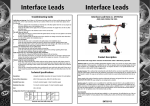
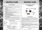
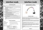
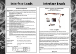
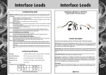
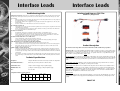
Interface Leads
Interface Leads
Troubleshooting Guide
Interface Lead Item nr. 67687 for
Carkit does not start up. Check if there is 12V between the black and the red wire and also between the black
and blue wire, in the 16 pin connector, when the car is started. If there is not 12v on both wires please check
the following:
1.
If there is supply on the red constant 12v wire but not on the blue ignition wire the car may require an
alternative ignition source. See installation step 5.
2.
Check that the bullets on the supply wires are properly connected. The supply wires are the red, blue
and black wires.
3.
Check for a blown fuse on the Interface Lead or in the cars fuse-box.
The carkit does not turn off.
1.
Please make sure the key is removed from the ignition barrel. On many new cars ignition is not turned
off until the key is pulled out.
2.
Is there an ignition supply on the blue wire? There should be no voltage on the blue wire when there
is no key in the ignition. See installation step 4.
Speakers are not muted.
1.
Check that the mute wire is connected to the right position. See installation step 3.
2.
Locate the radio instruction manual and check for special menu settings regarding phone input.
3.
Please check that there is close to 0V on the yellow mute wire during a call. If there are more than
approximately 0V the carkit may be defective please try another carkit.
Speakers are muted but there are no carkit sound.
1.
Please check that the carkit and radio volume is turned up.
2.
Locate the radio instruction manual and check for special menu settings regarding phone input.
3.
The carkit may be defective. Please try another carkit.
Radio will not turn on or not working properly after installation.
1.
Please check for a blown fuse at the back of the radio or in the car fuse-box.
2.
Please check that all connectors are properly connected and that there are no bend or damaged pins.
3.
Remove the Interface Lead and connect the radio to the original car connector. If the radio is now
working replace the Interface Lead.
Volume to high or sound is disordered.
1.
Please try to turn down the carkit volume and turn up the volume using the radio volume control instead. If the carkit volume has to be turned almost completely down improved adjustment range can
be achieved by connecting a inline resistor item number: 68897 inline with the white wire to limit the
carkit output.
2.
There may be a Ground loop problem when combining this exact carkit and radio model. Please try to
insert Ground loop isolator item number: 69897 inline with the white and white/black wires from the
carkit.
Technical Specifications
Description:
L-shaped with bullet connections for Ground, Constant 12v and Ignition.
Normal Wire dimensions :
AWG 18 for power wires, AWG 20 for all other wires
Standard Fuse sizes:
3 Amp for constant supply, 1 Amp for Ignition supply
Maximum Fuse size:
7,5 Amp for constant supply, 7,5 Amp for Ignition supply
Size:
400 x 400 mm
Configuration chart for 16 pin connector:
12V
Const.
12V
IGN
GND
Mute
Out
Mute
In
Carkit
RF+
Carkit
LF+
Carkit
RF-
Carkit
LF-
Connector seen from cable entry side
Land Rover / Range Rover
Product Description
The Interface leads range allows connection of Aftermarket carkits to OEM Phone preparation.
Interface Leads are used when installing aftermarket telephone carkits. It is used for car stereos with a Phone
Line-In function or VDA preparation. It enables the use of the car speakers when answering/making calls from
your cell phone. For a complete cable-set two item no. are required. The first is a car-specific Interface Lead.
The second is a carkit-specific Interface adaptor cable .
Speaker-function: This is achieved by connecting the carkit directly to the cars Line-In input/VDA connector. By
using the radios built-in switch function the telephone conversation is heard through the car speakers while the
radio sound is muted. This way you will achieve a perfect hands free sound without interference from the car
radio.
Power supply of the carkit: All Interface Leads are delivered with power and ground from the car connector
connected to the carkit, this way cutting the cars wiring loom is avoided.
Ignition supply: If an ignition source is available in the radio/VDA connector then it is also available in the 16
pin connector. If an ignition source is not available a constant 12V source is connected to the Ignition pin via
bullet connectors. If a real ignition is required for the chosen carkit, an IGNIBOX item no. “I” can be connected
to create an artificial ignition or an ignition source found elsewhere can be connected to the bullet with the
blue wire. The 12V ignition wires in the Interface leads are blue.
Aux integration
Some Interface leads have the radio AUX input available in a 4 pin connector. This will allow the use of the car
sound system amplifier for Music playback when installing Music carkits and thereby achieving higher audio
quality.
EN687-V2
Interface Leads
Installation description
Interface Lead Item nr. 67687 for
Interface Leads
6th. Insert the Interface Lead between the radio and the removed radio connectors. And refit all remaining
connectors.
Fly-wires
7th. Check ignition source. Not all models have an ignition source in the prewired position in the cable set.
Therefore it is possible to disconnect the blue ignition wire from the cable set and connect it to an ignition
source found elsewhere or the red constant 12v wire by using the bullet connectors . Alternatively a IGNIBOX
item nr. “I” can be inserted to generate an artificial ignition.
Land Rover / Range Rover
Needed items:
A: Interface Lead.
B: Interface Lead carkit adaptor.
C: Carkit.
Note: The Carkit C and Interface Lead adaptor B are bought separately.
Installation:
1st: Remove the key from the ignition barrel. This is done to
avoid error messages on the car electrical system.
Bullet Connectors
A: Interface Lead
Item number 67xxx
4 pin
Aux
16 pin Connectors
9th. Connect the carkit ‘C’ to the Interface Lead using the Interface Lead adaptor ‘B’. Interface Lead adaptors for Music carkit include a 4 pin AUX connector. This is used for connecting an optional Kram AUX solution. By
adding a Kram AUX solution you will achieve a much higher audio quality when playing music from the carkit
and the music will be heard in all speakers. Please see our website www.kram.dk for further information about
AUX solutions.
B: Interface Adaptor
Item number DAxxx
2nd. Remove the radio and disconnect the connectors from rear
of the radio.
3rd. Locate the 12 pin connector with red front.
The three fly-wires from the cable-set will need to be manually
inserted into this connector. See picture:
8th: Check fuse size. The fuse on the Audio2Car cable should not be bigger than the ones used on the wiring
loom supplied with the carkit. The fuses on the Audio2Car cable should be replaced with a size similar to the
ones supplied with the carkit.
Note: Never exceed the Maximum Fuse size for the Interface Lead. See maximum fuse sizes on the last page.
C: Carkit
10th. Test function and adjust volume. When the Interface Lead is installed correctly it will redirect your call
through the car front speaker. Adjust the volume setting using the carkit and radio volume control. Note that too
high carkit volume will distort the sound. If you do not get sound the Telephone input may need to be activated
in the radio menus. Please see radio manual for further information.
11th. If you are experiencing electrical noise in the car speakers when a call is in progress, you need to install
the ground-loop isolator coil delivered with the cable. The coil is installed inline with the white and white/black
audio signal wires from the carkit. The female bullets are the input and the male bullets are the output. Please
see picture below.
4th. Remover the red front insert from the 12 pin connector using a small screwdriver.
This is done to release the pin retainers. See pictures:
5th. Insert the fly-wires
The white and the white/black audio wires and the yellow mute can be inserted into the 12 pin connector. The
yellow wire should be inserted into slot 10, the White into slot 5 and the white/black into slot 3. Please see the
diagram below. Insert the pins with the correct side up, use the other pins as reference:
Connector seen from cable entry side
See our complete Interface Lead program on www.kram.dk