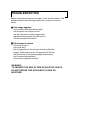
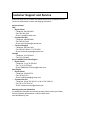
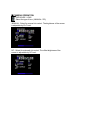
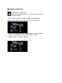
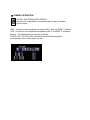
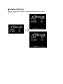
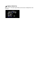
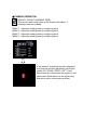
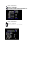
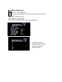
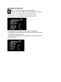
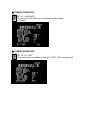
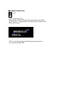
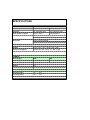
1
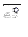
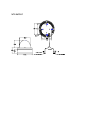
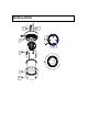
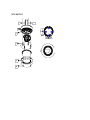
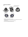
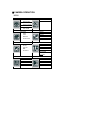
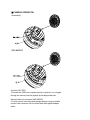
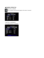
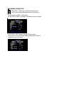
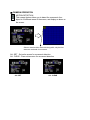
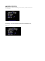
WZ45N Integrated Day/Night IR Dome
INSTRUCTION MANUAL
Before installing and using the camera, please read this
manual carefully. Be sure to keep it handy for later reference.
Important Safety Instructions
1. Read these instructions.
2. Keep this instruction.
3. Heed all warnings.
4. Follow all instructions.
5. Do not use this apparatus near water.
6. Clean inside only with dry cloth.
7. Do not block any ventilation openings. Install in accordance with
manufacturer instructions.
8. Do not install near any heat sources such as radiators, heat
registers, stoves or other apparatus (including amplifiers) that produce
heat.
9. Do not defeat the safety purpose of the polarized or grounding-type
plug. A polarized plug has two blades with one wider than the other.
A grounding type plug has two blades and a third grounding prong.
The wide blade or the third prong is provided for your safety. If the
provided plug does not fit into your outlet, consult an electrician for
replacement of the obsolete outlet.
10. Protect the power cord from being walked on or pinched
particularly at plugs, convenience receptacles, and the power where
they exit from the apparatus.
11. Only use attachments/accessories specified by the manufacturer.
12. Use only with the cart, stand, tripod, bracket, or table specified by
the manufacturer, or sold with the apparatus. When a cart is used,
use caution when moving the cart/apparatus combination to avoid
injury from tip-over.
13. Unplug this apparatus during lightning storms or when unused for
long periods of time.
14. Refer all servicing to qualified service personnel. Servicing is
required when the apparatus has been damaged in a way, such as
power-supply cord or plug is damaged, liquid has been spilled or
objects have fallen into the apparatus, the apparatus has been
exposed to rain or moisture, does not operate normally, or has been
dropped.
FCC Note
NOTE: This equipment has been tested and found to comply with the
limits for a Class B digital device, pursuant to part 15 of the FCC rules.
These limits are designed to provide reasonable protection against
harmful interference in a residential installation. As part of its’ normal
operation this device can generate radio frequency energy and if not
installed and used in accordance with the installation manual may
cause interference to radio communications. However, there is no
guarantee that interference will not occur on a particular installation. If
the device does cause interference to radio or television reception the
user is encouraged to try to correct the interference by one or more of
the following measures:
1) Fit Ferrite beads on all cable to and from the power
supply box, within the box walls.
2) Route the composite cable between the camera and the power
supply in steel conduit piping over the entire run of the cable up to and
including connection to a deep conduit base fitted under the camera
and a conduit fitting adaptor in the wall of the PSU box.
3) Contact a BOSCH Service Center for further advice.
CE Note
NOTE: This equipment has been tested and found to comply with the
limits for a Class A digital device, pursuant to EU Standard EN55022.
In a domestic environment this product may cause radio interference
in which case the user may be required to take adequate measures
Precautions
• Do not modify
• Do not put objects inside the unit. Make sure that no metal objects or
flammable substances enter the camera. This may cause fire, shortcircuits and other damages.
• Be careful when handling the unit. To prevent damage, do not drop
the camera or subject it to strong shock or vibration.
• Install the camera away from electric or magnetic fields.
• Protect the camera from humidity and dust.
• Do not subject the unit to high temperature. Be careful when
installing close to ceilings, in a kitchen or a boiler room as heat rises
and will affect the camera.
• Dirt can be removed from the exterior of the camera by wiping it with
a clean soft moistened cloth and soft detergent solution.
• The mounting surface material must be strong enough to secure the
camera.
TROUBLESHOOTING
Before sending the camera out for repair, check the items below. If the
problem persists after checking these items, contact your service
center.
■ If no image appears.
Is the coaxial cable attached securely?
Are the power and voltage normal?
Has the exposure/iris of the camera been
adjusted correctly (within the OSD menu) ?
Is there adequate illumination?
■ If the image is unclear
Is the lens in focus?
Is the lens dirty?
Dirt of fingerprints on the lens can adversely affect the
images. Gently wipe any dirt or fingerprints off the lens
with a soft cloth or lens cleaning paper and cleaning
fluid (commercially available).
Is the monitor adjusted correctly?
WARNING:
TO PREVENT THE RISK OF FIRE OR ELECTRIC SHOCK,
DO NOT EXPOSE THIS APPLIANCE TO RAIN OR
MOISTURE.
Customer Support and Service
If this unit needs service, contact the nearest Bosch Security Systems Service
Center for authorization to return and shipping instructions.
Service Centers
USA
– Repair Center
– Telephone: 800-366-2283
– Fax: 800-366-1329
– E-mail: [email protected]
– Customer Service
– Telephone: 888-289-0096
– Fax: 585-223-9180
– E-mail: [email protected]
– Technical Support
– Telephone: 800-326-1450
– Fax: 585-223-3508 or 717-735-6560
– E-mail: [email protected]
Canada
– Telephone: 514-738-2434
– Fax: 514-738-8480
Europe, Middle East, Africa Region
– Repair Center
– Telephone: 31 (0) 76-5721500
– Fax: 31 (0) 76-5721413
– E-mail: [email protected]
Asia Region
– Repair Center
– Telephone: 65 63522776
– Fax: 65 63521776
– E-mail: [email protected]
– Customer Service
– Telephone: 86 (0) 756 7633117 or 86 (0) 756 7633121
– Fax: 86 (0) 756 7631710
– E-mail: [email protected]
Warranty and more information
For additional information and warranty queries, please contact your Bosch
Security Systems representative or visit our Web site at
www.boschsecurity.com.
DIMENSIONS (mm)
*UTP OUTPUT
INSTALLATION
E
D
C
A
B
F
*UTP OUTPUT
E
D
C
A
B
INSTALLATION
1
Use the supplied security tool to remove the four
fixing screws (B) of dome ring (A).
2
Align the supplied mounting template with the surface to be
mounted to, make marks on the surface in the places
where the screw holes and cable hole are to be located.
3
Drill holes for the screws and cable hole in the surface
1inch (25mm) in diameter, for routing the cables.
Alternatively the cables can pass through the side entry
via the 1/2 inch NPT cable entry, ensure unit is
appropriately sealed with any method used.
4
Pass the power cable (E) and video cable (F) or
UTP cable (*F) from the camera unit through
the cable hole in the surface or out the side entry.
5
Align the four screw holes in the camera unit (D) with
the screw holes on the mounting surface, and then secure
the camera in place by fastening the four screws (C)
through the camera unit into the surface.
6 Carry out the settings and adjustments for the camera as
covered in the next sections.
7 Secure the dome ring (A) by tightening the screws (B) into
the camera unit (D). Ensure the rubber ring between the
lens and the dome cover is in place and forms a tight seal
against the inside of the dome.
CONNECTIONS AND CAMERA SETTINGS
■ CONNECTIONS
DC12V / AC24V
*UTP OUTPUT
CAUTION :
Check for polarity when using a DC 12V power supply.
■ LENS ADJUSTMENTS
Twist adjustment setscrew
(one on each side)
1. Adjust the pan (360˚) and tilt (70˚) position.
2. Adjust the twist position by loosening setscrews with supplied allen key and twist the
camera module.
3. Set the zoom position by using the zoom thumb screw.
4. Set the focus by using the focus thumb screw.
■ CAMERA OPERATION
MENU
1. EXPOSURE
LENS
MANUAL/DC
E. SHUTTER
5. MOTION
ALRAM
AUTO~1/100000
BLC
AGC
OFF~36dB
2. COLOR
WB MODE
AWC
ATW
MANUAL
PUSH LOCK
3. DAY&NIGHT
D&N MODE
AUTO
COLOR
B/W
EX-CONT
4. FUNCTION
MIRROR
SHARPNESS
GAMMA
SLC
HME
DRC
6. PRIVACY
MASK 1
MASK 2
MASK 3
MASK 4
COLOR SET
7. SETUP
CAMERA ID
TITLE EDIT
TITLE RESET
TITLE POSITION
DPC SET
LANGUAGE
PC CONT.
8. EXIT
EXIT
SAVE & EXIT
FACTORY SET
■ CAMERA OPERATION
Accessibility
*UTP OUTPUT
Joystick (JOY KEY)
To access the OSD menu system press the joystick in, to navigate
through the menus push the joystick to the appropriate side.
Second video out connector (2ND VIDEO)
To verify correct view angle and change settings using a portable
monitor, this connector can be utilized with the supplied adapter
cable.
■ CAMERA OPERATION
EXPOSURE - LENS
Select the type of lens ( MANUAL / DC)
MANUAL : Select for manual iris control. The brightness of the screen
is adjustable by ELC level.
DC : Select for automatic iris control. The offset brightness of the
screen is adjustable by DC level.
■ CAMERA OPERATION
EXPOSURE - E.SHUTTER
This mode is selectable to either Auto or Fixed control for the
electronic shutter.
AUTO : Set for complete automatic operation of the electronic
shutter, only available when lens iris control is set to Manual.
FIXED : Set to desired minimum shutter speed, 10 levels available.
1/50s(PAL),1/60s(NTSC),1/100s,1/250s,1/500s,1/1000s,
1/2000s,1/4000s,1/10000s,1/100000s)
■ CAMERA OPERATION
EXPOSURE - BLC (Back Light Compensation)
When there is a strong backlight in the scene, change BLC in order
to get a uniform image.
By selecting "BLC ON", BLC activity area and level are adjustable in 5
sections (TOP / DOWN / CENTER / RIGHT / LEFT). Increase the level in
areas desired to become brighter for compensation.
■ CAMERA OPERATION
EXPOSURE - AGC (Auto Gain Control)
This function is designed to automatically adjust video gain to
enhance the picture in darker scenes.
AGC is adjustable within OFF - 36dB.
■ CAMERA OPERATION
COLOR - WHITE BALANCE CONTROL
Screen color is adjustable in accordance with the type of ambient
light on scene.
AWC : Use this for color temperatures below 2500 °C and over 9500°C (indoors)
ATW : Use this for color temperatures between 2500 °C and 9500 °C (outdoors)
Manual : The white balance is manually controlled.
PUSH LOCK : If PUSH LOCK is selected, the white balance adjusts
automatically for the current light on scene.
■ CAMERA OPERATION
Manual : Adjust RED or BLUE in accordance with the type of ambient
light on scene.
■ CAMERA OPERATION
COLOR - GAIN CONTROL
Select the desired gain value. The higher the gain level, the more
the scene displays that color.
R-Y GAIN : Adjustment of RED color
B-Y GAIN : Adjustment of Blue color
■ CAMERA OPERATION
DAY & NIGHT (AUTO / COLOR / B/W)
This function determines how day and night modes are handled.
AUTO : The camera automatically switches between day and night
mode depending on the light level.
COLOR : The camera stays in day mode.
B/W : The camera stays in night mode.
BURST SIGNAL : If ON, the screen shows a color burst while switching to
day mode from night mode.
SET LEVEL : Not adjustable.
READ TIME : The switching time delay in AUTO mode for when the scene
suddenly gets darker or brighter, adjustable from 3 secs to 12 secs.
■ CAMERA OPERATION
FUNCTION - MIRROR
If ON is selected, the horizontal image on the screen is reversed.
FUNCTION - SHARPNESS
The image sharpness is adjustable.
■ CAMERA OPERATION
FUNCTION - GAMMA
GAMMA LEVEL is selectable in 3 levels. 0.45, 0.6, 1.0.
FUNCTION - SLC (SIDE LIGHT COMPENSATION)
Select this mode when the corner of the screen is darker than the
center.
As the level increases the image becomes brighter
■ CAMERA OPERATION
FUNCTION - HME (High Light Masking Exposure)
This function masks the bright areas on the screen.
The brightness of HME is adjustable.
As the level of HME is increased, the masking area increases.
FUNCTION - DRC (Dynamic Range Compensation)
This function is to compensate darker images when different
exposures are in one scene.
■ CAMERA OPERATION
MOTION DETECTION
This camera feature allows you to detect the movement of an
object in 64 different areas of the screen, and display an alarm on
the screen.
Select or deselect blue areas with the joystick, only the blue
areas are monitored for movement.
ALL SET : Set entire screen for movement detection.
ALL CLEAR : Clear entire screen for movement detection.
ALL SET
ALL CLEAR
■ CAMERA OPERATION
Sensitivity level : As the sensitivity level increases, smaller movements
are detected.
SHOW INDI : The motion detected indicator can be selected as icon,
trace or off.
■ CAMERA OPERATION
DELAY OUT : The alarm signal display on the screen is delayed from 1sec
to 15 sec.
■ CAMERA OPERATION
PRIVACY (PRIVACY MASKING ZONE)
This function sets certain areas of the screen to be hidden. 4
masking zones are available.
MASK 1 :
MASK 2 :
MASK 3 :
MASK 4 :
Adjust the masking area by using the joystick.
Adjust the masking area by using the joystick.
Adjust the masking area by using the joystick.
Adjust the masking area by using the joystick.
If "set window" is selected, the cell is displayed
on the screen and then adjusted by moving the
joystick UP / DOWN / RIGHT / LEFT. Once
desired area is covered press the joystick in until
mask area is black then move the joystick any
direction to return to the previous screen.
■ CAMERA OPERATION
PRIVACY - COLOR SET
This function is to select the color of the masking cells.
■ CAMERA OPERATION
SET UP - CAMERA ID
Enter a camera ID as a unique identifier.
■ CAMERA OPERATION
SET UP - TITLE DISPLAY
Camera title is displayed on the screen when a value is entered.
TITLE EDIT : Select the value
TITLE RESET : Clears the title.
TITLE POSITION SELECTION : Set area to display title.
If editing the title, this
image is displayed, select
desired characters by
using the joystick.
■ CAMERA OPERATION
SET UP - DPC SET (Defect Pixel Cancellation)
This function automatically removes dead pixels in real time.
WHITE THR. : For cancelling the white defective pixels.
BLACK THR. : For cancelling the black defective pixels.
The cancellation sensitivity of defect pixels is adjustable.
For adjusting white defective pixel sensitivity, set WHITE THR. and
DPC LEVEL at the same time.
For adjusting black defect pixel, set BLACK THR and DPC LEVEL
at the same time.
■ CAMERA OPERATION
SET UP - LANGUAGE
The language of the OSD menu is selectable to either English
or Chinese.
■ CAMERA OPERATION
SET UP - PC CONT.
PC communication is available by setting PC CONT. "ON" (not supported)
■ CAMERA OPERATION
EXIT
EXIT : Exit the OSD menu.
SAVE & EXIT : Exit the OSD menu after saving the current setting.
FACTORY SET : Change setting to the factory default. (make sure to
SAVE & EXIT after)
NOTE : Lens, Day & Night and ID/Title settings stay the same
even after a FACTORY SET.
SPECIFICATIONS
MODEL
WZ45N (all m odels)
General Spec
NTSC
PAL
CCD Type
1/3" 410K Pixels Color
1/3" 470k Pixels Color
Total num ber of pixels
811(H) X 508 (V)
795(H) X 596(V)
Min illum ination
0.1Lux [(F1.2, 30IRE), (at COLOR)]
0.001Lux [(F1.2, 30IRE), (at TDN(B/W)]
Resolution
520 TV Lines [at COLOR]
580 TV Lines [at TDN(B/W)]
Electric Spec
Voltage
DC 12V (10V ~ 16V) AC 24V (20V ~ 28V)
Pow er Consum ption
LED ON = DC : Max 4.3 [W] AC : Max 4.3 [W]
COMMON
General Spec
NTSC
PAL
Shutter speed
1/60s - 1/100,000s
1/50s - 1/100,000s
S/N Ratio
50dB or more(AGC off)
Gam m a
0.45
Sync System
Internal / External
Mechanical Spec
Operation tem p
-30℃ ∼ +55℃
In storage tem p
-30℃ ∼ +70℃
Operation hum idity
Under 90% (Non-condensing)
Americas
Bosch Security Systems, Inc.
850 Greenfield Road
Lancaster, Pennsylvania 17601
USA
Telephone+1 888-289-0096
Fax +1 585-223-9180
Email: [email protected]
www.boschsecurity.us
Europe, Middle East, Africa:
Bosch Security Systems B.V.
P.O. Box 80002
5600 JB Eindhoven,
The Netherlands
Phone: + 31 40 2577 284
Fax: +31 40 2577 330
[email protected]
www.boschsecurity.com
Asia-Pacific:
Bosch Security Systems Pte Ltd
38C Jalan Pemimpin
Singapore 577180
Phone: +65 6319 3450
Fax: +65 6319 3499
[email protected]
www.boschsecurity.com
© Bosch Security Systems, Inc. 2009; Data subject to change
without notice.