1
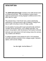
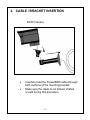
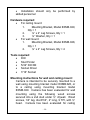
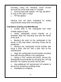
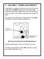
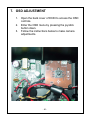
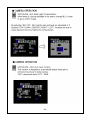
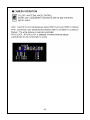
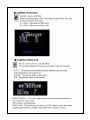
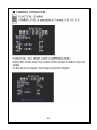
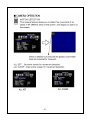
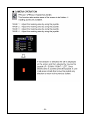
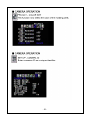
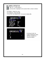
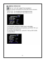
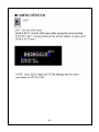
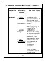
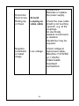
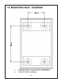
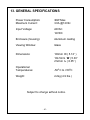
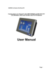
INSTALLATION INSTRUCTION
EX30
Infrared Imager™
MAN-30-06
-1-
IMPORTANT SAFETY INSTRUCTIONS
1.
Read these instructions.
2.
Keep this instruction.
3.
Heed all warnings.
4.
Follow all instructions.
5.
Do not use this apparatus near water.
6.
Clean only with dry cloth.
7.
Do not block any ventilation openings. Install in
accordance with manufacturer instructions.
8.
Do not install near any heat sources such as
radiators, heat registers, stoves or other
apparatus (including amplifiers) that produce
heat.
9.
Do not defeat the safety purpose of the polarized
or grounding-type plug. A polarized plug has two
blades with one wider than the other. A
grounding type plug has two blades and a third
grounding prong. The wide blade or the third
prong is provided for your safety. If the provided
plug does not fit into your outlet, consult an
electrician for replacement of the obsolete outlet.
-2-
10. Protect the power cord from being walked on or
pinched particularly at plugs, convenience
receptacles, and the power where they exit from
the apparatus.
11. Only use attachments/accessories specified by
the manufacturer.
12. Use only with the cart, stand, tripod, bracket, or
table specified by the manufacturer, or sold with
the apparatus. When a cart is used, use caution
when moving the cart/apparatus combination to
avoid injury from tip-over.
13. Unplug this apparatus during lightning storms or
when unused for long periods of time.
14. Refer all servicing to qualified service personnel.
Servicing is required when the apparatus has
been damaged in a way, such as power-supply
cord or plug is damaged, liquid has been spilled
or objects have fallen into the apparatus, the
apparatus has been exposed to rain or moisture,
does not operate normally, or has been dropped.
-3-
®
IMPORTANT
For best results, please read this Instruction Booklet
prior to installing the EX30 Infrared Imager.
WARNING !
CSA Certified / UL Listed CLASS 2 power adaptors must be used
in order to comply with electrical safety
Only qualified personnel shall install any EXTREME CCTV®surveillance
camera. EXTREME CCTV® will not be responsible for injuries or
damages resulting from the improper installation
or use of any equipment sold by EXTREME CCTV®,
their agents, distributors or dealers.
-4-
NOTE: This equipment has been tested and found to
comply with the limits for a digital device, pursuant to part
15 of the FCC rules. These limits are designed to provide
reasonable protection against harmful interference in a
residential installation. As part of its’ normal operation this
device can generate radio frequency energy and if not
installed and used in accordance with the installation
manual may cause interference to radio communications.
However, there is no guarantee that interference will not
occur on a particular installation. If the device does cause
interference to radio or television reception the user is
encouraged to try to correct the interference by one or
more of the following measures:
1) Fit Ferrite beads on all cable to and from the power
supply box, within the box walls.
2) Route the composite cable between the camera and the
power supply in steel conduit piping over the entire run of
the cable up to and including connection to a deep conduit
base fitted under the camera and a conduit fitting adaptor in
the wall of the PSU box.
3) Contact BOSCH Service Center for further advice.
-5-
INDEX – EX30 Infrared Imager™
PAGE
DESCRIPTION................................................................. 7
UNPACKING.................................................................... 8
PARTS LIST .................................................................... 8
ITEMS REQUIRED FOR INSTALLATION....................... 8
INITIAL PREPARATIONS ............................................... 9
GUIDELINES ................................................................... 9
1. MOUNTING BRACKET PREPARATION ................ 10
2. CABLE / BRACKET INSERTION ............................ 11
3. MOUNTING BRACKET ATTACHMENT ................. 12
4. CAMERA MOUNTING ............................................ 13
5. CAMERA LENS ADJUSTMENTS AND SELECTING
THE WINDOW ............................................................... 16
6. LED ARRAY - POWER ADJUSTMENTS................ 19
7. OSD ADJUSTMENT ............................................... 20
8. OSD MENU............................................................. 21
9. CAMERA RE-ASSEMBLY ...................................... 40
10. TROUBLESHOOTING GUIDE -CAMERA .............. 41
11. TROUBLESHOOTING GUIDE – LEDs ................... 45
12. MOUNTING HOLE - DIAGRAM .............................. 46
13. GENERAL SPECIFICATIONS ................................ 47
-6-
DESCRIPTION
The EX30 Infrared Imager consists of an LXR camera and
an infrared illuminator. This surveillance system gives
optimum performance during daylight conditions and in the
pitch black of night.
The camera has a “Vari Focal” lens, and is seamlessly
switched by a photocell when light conditions change from
day to night, ensuring no loss of image quality.
An all-weather housing with tough polycarbonate windows
contains all the electronics. Low voltage operation, low
power consumption, LED illuminators, thermostat controlled
defroster and solid-state CCD technology make this camera
very reliable and efficient.
A voltage regulator circuit allows for DC or AC operation,
and also provides protection from voltage surges, transient
spikes, and reverse voltage.
See the Light. Get the Picture.™
-7-
UNPACKING
Care should be taken when unpacking the shipped unit.
Check the parts list and confirm all items have been
located. Inspect the equipment thoroughly to ensure
nothing was damaged in transit.
Contact BOSCH Service Center if a problem is noted,
see the rear page of this booklet for contact numbers.
PARTS LIST
(items supplied with unit)
-
EX30 camera assembly
Installation Instructions booklet
Cardboard box containing one adjustable wall mounting bracket.
Extra window (80º illumination beam)
ITEMS REQUIRED FOR INSTALLATION
(not supplied with units)
•
•
•
Mounting hardware
Mounting tools
Camera Power Supply
-8-
INITIAL PREPARATIONS
•
Determine the operating voltage at the
installation site. The camera‘s Voltage Regulator
Board accepts both 10.5-40VDC and 12-28VAC
input without change to internal connections.
•
Determine the optimum mounting location for
the camera. See Section 4, Camera Mounting.
•
All cameras have been tested and pre-focused
with telephoto setting as factory default prior to
shipment. If any adjustment needed, it is
advisable to check the camera’s operation
before installation.
GUIDELINES
The installation of the EX30 camera is explained in
Sections 1 to 7.
It is important that these steps are followed in numerical
order.
It is also important to follow proper safety guidelines
when installing this product.
-9-
1. MOUNTING BRACKET PREPARATION
EXMB.028
Mounting Bracket
SET SCREW
•
•
Use the supplied Allen Key to remove the
setscrew from the supplied mounting
bracket.
Separate the two sections of the mounting
bracket.
- 10 -
2. CABLE / BRACKET INSERTION
EX30 Camera
•
•
Carefully feed the Power/BNC cable through
both sections of the mounting bracket.
Make sure the cable is not kinked, chafed,
or split during this procedure.
- 11 -
3. MOUNTING BRACKET ATTACHMENT
•
•
•
•
Attach the Mounting Bracket to the Camera’s
Mounting Block using the six bolts supplied
with the bracket.
Snug the two halves of the bracket together
with the Allen head set screw.
Tighten the setscrew enough so that the
camera can be adjusted for angle. Do not
over-tighten.
Note the angled part of the mounting bracket
faces to the rear of the camera.
- 12 -
4. CAMERA MOUNTING
Warning: this apparatus must be securely
attached to the wall or ceiling in accordance with
installation instructions. Failure to follow
installation instructions ma results in
injury/death.
Select a suitable location that protects the camera
from accidental damage, tampering and
environmental conditions exceeding the specifications
of the camera to be mounted.
Caution: Ensure the selected location is protected
from falling objects, accidental contact with moving
objects and unintentional interference from personnel.
Follow all applicable building codes.
&The following installation guidelines must be
followed:
•
Locate the bracket such that it cannot be
easily interfered with, either intentionally or
accidentally.
•
Select a smooth, flat mounting surface to
ensure proper sealing. The surface must also be
capable of supporting the combined weight of the
camera and mounting hardware under all
expected conditions of vibration and temperature.
•
Secure all cabling.
- 13 -
•
Installation should only be performed by
skilled personnel
Hardware required:
•
For ceiling mount:
1.
Mounting Bracket, Model EXMB.029,
Qty = 1
2.
¼’’ x 2” Lag Screws, Qty = 1
3.
¼’’ Washer, Qty = 1
•
For wall mount:
1.
Mounting Bracket, Model EXMB.028,
Qty = 1
2.
¼’’ x 2” Lag Screws, Qty = 4
Tools required:
•
Drill
•
Stud Finder
•
5/32” Drill Bit
•
Socket Driver
•
7/16” Socket
Mounting instructions for wall and ceiling mount:
Camera is intended to be securely mounted to a
wall using mounting bracket model EXMB.028, or
to a ceiling using mounting bracket model
EXMB.029. Camera has been evaluated for wall
mounting using the following wood screws
secured into a 2x4 stud under ½” drywall. Wood
screws, 1/4” lag, dia Ø1/4”, 2” long, 9 TPI, with ½”
head. Camera has been evaluated for ceiling
- 14 -
mounting using the following wood screws
secured into a 2x4 stud under ½” drywall:
•
wood screws with washer, 1/4” lag, dia Ø1/4”,
2” long, 9 TPI, with ½” head
•
16” flat washer.
Camera has not been evaluated for safety
requirements using other mounting kits.
Installation (Ceiling and Wall Mount)
•
Locate stud in the ceiling/wall and mark
outside edges of stud.
•
Using ceiling/wall mount bracket as a
template, align the mounting hole with the center
of the stud.
•
Marking the point on the ceiling/wall in the
center of the hole where mounting screw will be
positioned.
•
Remove the ceiling/wall mount bracket and
using a 5/32” drill bit, drill a pilot hole at the
marked point.
•
Align the ceiling/wall mount bracket mounting
hole with the hole drilled in the ceiling/wall
•
Using a 7/16” socket and driver, secure the
ceiling/wall mount bracket by screwing the 1/4” lag
bolt with 1/4” washer securely into the stud.
•
Use additional 1/4” lag bolt and 1/4” washer to
secure the remaining mounting holes.
•
Installation is complete.
- 15 -
5. CAMERA LENS ADJUSTMENTS AND
SELECTING THE WINDOW
For optimum picture quality, the camera lens should
be as close as possible to the inside face of the
viewing window, without touching.
The camera is pre-focused with telephoto
setting as factory default. Follow the steps below if
any adjustment needed.
•
•
•
Loosen the four bolts from the extrusion.
Remove the faceplate, window and the lens foam, set
aside. Make sure the photocell is not dislodged.
Do proper adjustment as 5.1
Loosen the four bolts
- 16 -
Loosen this setscrew
for Focus Adjustment
Loosen this setscrew
for Telephoto or Wide
Angle Adjustment
5.1. Vari Focal and “Auto-Iris” Control Adjustments
•
•
•
•
Loosen the lens set screws for focus/zoom
adjustments.
The setscrew marked N ←→ ∞ is used for image
focus.
The setscrew marked T←→ W is used for telephoto
or wide-angle settings.
Re-tighten the setscrews after focus adjustments
have been completed.
Window Selection
- 17 -
Telephoto (Factory standard)
Use 40º illumination beam
Wide
Use 80ºillumination beam
Use a Neutral Density filter or Infra-Red Pass filter to cover
the lens during focusing to simulate low light conditions on
scene for correct 24-hour focusing. For camera with varifocal lens, the camera should be focused with the lens iris
fully opened to simulate the worst possible depth of field.
Using a Neutral Density filter or Infra-Red Pass filter will
ensure the iris is fully open for correct setup and
adjustment.
Note that statement above is applicable only for Day/Night
or IR version cameras.
- 18 -
6. LED ARRAY - POWER ADJUSTMENTS
If adjustment is needed, remove the rear cover for access
to the LRB. The EX30 needs to be powered-up while
making the LED power adjustments. Cover the photocell
to turn the LEDs “ON” (850nm LEDs will have a slight red
glow).
For photocell “On/Off” light-level adjustment, rotate VR2.
Clockwise is off and counter-clockwise is on.
LED Power
Adjustment
Photocell On/Off
Adjustment
LED Power and Photocell On/Off Adjustments
Adjust the LED power if they are too bright or too dim.
For IR power adjustment, rotate VR1. Clockwise is high
and counter-clockwise is low.
- 19 -
7. OSD ADJUSTMENT
1.
2.
3.
Open the back cover of EX30 to access the OSD
controls.
Enter the OSD menu by pressing the joystick
button down.
Follow the instructions below to make camera
adjustments.
- 20 -
8. OSD MENU
- 21 -
Note
The following default settings should not be changed:
Lens = DC; E.Shutter = Auto
- 22 -
- 23 -
- 24 -
- 25 -
- 26 -
- 27 -
Note
The following default setting should not be changed.
Day & Night = Auto
- 28 -
- 29 -
- 30 -
- 31 -
- 32 -
- 33 -
- 34 -
- 35 -
- 36 -
- 37 -
- 38 -
- 39 -
9. CAMERA RE-ASSEMBLY
Make sure all wires are properly connected, all holes
are sealed against moisture penetration, and all
mounting screws are tight.
•
•
•
•
Slide the lens foam over the camera lens. Make
sure the foam is snug and as close to the
faceplate viewing window as possible and the
photocell is secure with an unobstructed view.
Attach the window, faceplate, and the rear cover
to the camera housing. Tighten the four bolts.
Tighten the camera’s adjustable mounting
bracket after the desired viewing angle has been
determined.
Power-up the camera and check its operation.
- 40 -
10. TROUBLESHOOTING GUIDE -CAMERA
PROBLEM
No Video
POSSIBLE
CAUSE
1. Power
Supply:
Connections
….
-Voltage
Range...
2. Video
Connections
LIKELY SOLUTION
Check the input
power connections at
the terminal block,
ensuring no wires are
loose.
The supply range is:
12-28VAC or
10.5-40VDC.
Measure the voltage
at the terminal block.
Determine if the
wiring polarity at the
“Video Connector”
terminal block is
correct.
Check BNC
connector.
If still no video,
connect the camera
directly to the
- 41 -
monitor. Check the
video signal. If okay,
the problem is with
the interconnections.
If still no video,
contact BOSCH
Service Center.
See rear page of
this manual for
contact information.
Poor
Picture
Quality
Dim Image
Snowy
Image
Iris closed
Poor Video
Signal
Noisy
Power
Supply
- 42 -
Increase iris level on
lens
Ensure the video
cable is correctly
matched and
terminated with 75
ohms at each end.
Make sure the video
cables are of similar
types.
Check all power
Horizontal
Scan Lines,
Rolling Up
or Down
Negative,
scrambled,
or faded
image
connections.
Relocate or replace
the power supply.
Ground
Looping on
video cable
Low voltage
Check the coax cable
shield is not touching
“ground”, e.g. at the
couplings.
An electrically
isolated circuit board
or isolation
transformer may be
required.
Check voltage at
input power cable.
Must be >10.5VDC
or >12VAC.
Video leads
reversed
connection.
- 43 -
- 44 -
11. TROUBLESHOOTING GUIDE – LEDs
PROBLEM
Fuse
Blows
Don’t
know if
LEDS are
“ON”
LEDs are
not “ON”
LEDs are
not turning
“OFF”
when
sufficient
ambient
light is
present
POSSIBLE SOLUTION
- Check the fuse rating.
- Check for shorting between the
housing and the input power wires.
- 850nm LEDs will have a faint red
glow when “ON”. 940nm LEDs are
covert.
- Aim the LEDs directly at an IR
sensitive camera, or use a mirror to
see the lights through the EX30
camera, or wait for the LEDs to
warm up (two minutes).
- Cover the photo sensor to activate
power to the LEDs (up to 30
seconds delay for activation).
- Adjust the photocell’s variable
resistor towards the “ON” position.
- Adjust power to the LEDs.
- Make sure the photo sensor is not
covered or hidden behind any
object.
- Adjust the photocell’s variable
resistor towards the “OFF” position
(up to 30 seconds delay). The LEDS
will stay “ON” or “OFF” if the
adjustments are at full turn.
- 45 -
12. MOUNTING HOLE - DIAGRAM
•
•
All dimensions expressed in millimeters
1.59” X 3.38” in inches
- 46 -
13. GENERAL SPECIFICATIONS
Power Consumption:
Maximum Current:
36W Max.
3.0A @12Vdc
Input Voltage:
24VAC
12VDC
Enclosure (housing):
Aluminum casting
Viewing Window:
Glass
Dimensions:
130mm H ( 5.12” )
134.5mm W ( 5.30”
212mm L ( 8.35” )
Operational
Temperatures:
0
0
-50 C to +50 C
Weight:
2.2kg (4.9 lbs.)
Subject to change without notice.
- 47 -
Note:
- 48 -
Americas
Bosch Security Systems, Inc.
850 Greenfield Road
Lancaster, Pennsylvania 17601 USA
Telephone+ 1 888-289-0096
Fax
+ 1 585-223-9180
Email: [email protected]
www.boschsecurity .us
Europe, Middle East, Africa:
Bosch Security Systems B.V.
P.O. Box 80002
5600 JB Eindhoven, Netherlands
Phone: + 31 40 2577 284
Fax: + 31 40 2577 330
[email protected]
www.boschsecurity.com
Asia Pacific:
Bosch Security Systems Pte Ltd.
38C Japan Pemimpin
Singapore 577 180
Phone: +65 6319 3450
Fax: +65 6319 3499
[email protected]
www.boschsecurity.com
© Bosch Security Systems., Inc. 2009; Data subject
to change with out notice
- 49 -