1
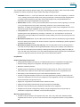
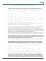
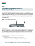
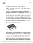
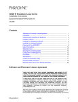
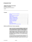
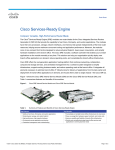
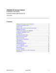
Data Sheet
Cisco Third-Generation 1-, 2-, and 4-Port T1/E1 Multiflex Trunk
Voice/WAN Interface Cards
These flexible interface cards support multiple integrated data, voice and video applications, facilitating the
migration from data only as well as circuit-switched voice/video services to a packet voice/video solution
Introduction
®
The Cisco Third-generation 1-, 2-port and 4-port T1/E1 Multiflex Trunk Voice/WAN Interface (MFT VWIC3s) support
data and voice applications on the Cisco 1921, 1941 and 1941W (data only), and the Cisco 2901, 2911, 2921, 2951,
3925, 3945, 3925E and 3945E Integrated Services Routers. The Cisco MFT VWIC3 combines WAN-interface-card
(WIC) and voice-interface-card (VIC) functions to provide unparalleled flexibility, versatility, and investment
protection through its many uses. Customers who choose to integrate data and voice in multiple steps preserve their
investment in a T1/E1 WAN interface because the Cisco MFT VWIC3 cards can be reused in packet voice
applications. The 2 port T1/E1 MFT VWIC3 is shown below.
Figure 1.
Cisco 1-,2- and 4-Port T1/E1 MFT VWIC3
The Cisco MFT VWIC3 interface cards add improvements over the Cisco Second-generation 1- and 2-port T1/E1
Multiflex Voice/WAN Interface Cards (MFT VWIC2s). The Cisco 2- and 4-port MFT VWIC3s enable each port to be
clocked from an independent clock source for data applications. Voice applications can now be clocked
independently from data applications, with all ports for voice applications clocked from a single source. The Cisco
MFT VWIC3s use the ECAN on the motherboard PVDM cards with up to 128ms echo-tail length for demanding
network conditions. MFT VWIC3 cards support up to 2 channel groups per T1/E1 port for serial data applications.
Refer to Table 3 for all configuration options offered with the MFT VWIC3 cards.
The Cisco MFT VWIC3 cards can be inserted into the EHWIC slot on the supported Cisco 1921, 1941, 1941W,
2901, 2911, 2921, 2951, 3925, 3945, 3925E and 3945E integrated services routers. The T1/E1 MFT VWIC3 cards
support both T1 and E1, providing additional flexibility in configuring the Cisco MFT VWIC3s for supporting T1,
fractional T1, E1, and fractional E1 for both voice and WAN applications. All MFT VWIC3 modules include the dropand-insert multiplexing capability, which eliminates costly external third-party channel service units/data service units
(CSUs/DSUs) and drop-and-insert multiplexers.
© 2010 Cisco and/or its affiliates. All rights reserved. This document is Cisco Public Information.
Page 1 of 9
Data Sheet
The Cisco MFT VWIC3 cards are offered in single-, dual- and quadruple-port versions, which can be used and then
redeployed as network requirements change, thereby addressing several applications:
●
T1/E1 data: The Cisco 1-, 2- and 4-port T1/E1 MFT VWIC3 versions act as a WIC, supporting T1, fractional
T1, E1, (including structured G.703 with G.704 framing), fractional E1, and E1structured G.703 applications.
To simplify remote management, these MFT VWIC3 cards integrate a fully managed DSU/CSU for T1
deployments and a fully managed DSU for E1 deployments.
●
E1/G.703 data: The Cisco 1- and 2- port G.703 MFT VWIC3 versions act as a WIC, supporting T1, fractional
T1, E1 (including structured G.703 with G.704 framing), fractional E1, and unstructured E1 (G.703)
applications. To simplify remote management, the G.703 version includes a fully managed DSU. The G.703
versions also support all the capabilities on the T1/E1 versions.
●
T1/E1 packet voice: The Cisco 1-, 2- and 4-port T1/E1 MFT VWIC3 (voice and WAN) versions act as a VIC,
supporting packet voice applications by providing T1, fractional T1, E1, and fractional E1 connections to
private branch exchanges (PBXs) and central offices, thereby enabling new services and reducing voice and
fax toll charges.
●
Mixed data and packet voice: The Cisco MFT VWIC3 interface cards can simultaneously support both data
and voice, reducing the complexity and number of network components and facilitating a graceful migration to
bandwidth-efficient packet voice.
●
Mixed data and packet voice with drop and insert: The Cisco MFT VWIC3 cards can be deployed as a
T1/E1 drop-and-insert multiplexer with integrated DSUs/CSUs, reducing the complexity of the network and
the cost of the central-office ports by efficiently combining time-division multiplexing (TDM) voice (PBX), IP
voice, and data on the same trunks. Cisco 1900, 2900 and 3900 ISR routers support drop and insert between
ports over a single MFT VWIC3 card and two ports over two different MFT VWIC3s
Key Benefits
Reduces Networking Lifecycle Costs
●
Enables graceful migration from data-only to multiplexed data and voice to packetized voice applications
●
Reduces training, deployment, management, and sparing inventory over single-purpose interfaces
●
Maximizes investment protection
●
Simplifies network configuration and sparing through the support of both T1 and E1 on the same card
●
Offers multifunction support for LAN-to-LAN routing, multiplexed data and voice, and packetized voice
●
Offers ability to share modules among Cisco 1900, 2900 and 3900 Series routers
●
Increases configuration flexibility and reduces cost for data applications by allowing individual ports to be
clocked from independent clock sources (not supported for voice applications, since all voice enabled ports
must be clocked from a single clock source)
●
Supports E1 configurations for both balanced and unbalanced modes
●
Supports (G.703 models) unstructured E1 (G.703) for using the full 2.048 Mbps
●
Eliminates costly external third-party CSUs/DSUs and drop-and-insert multiplexers
●
Simplifies remote network management by allowing a single management tool such as CiscoView or
CiscoWorks to support router, CSU/DSU, or drop-and-insert multiplexer
Maximizes System Resources
●
Increases T1/E1 port density on the supported Cisco 2911, 2921, 2951, 3925, 3945, 3925E and 3945E
integrated services routers—up to four T1/E1 connections with an integrated CSU/DSU in a single EHWIC
slot
© 2010 Cisco and/or its affiliates. All rights reserved. This document is Cisco Public Information.
Page 2 of 9
Data Sheet
●
Offers easy migration to bandwidth-efficient packet voice, enabling new services
Customers can choose to integrate data and voice in stages to preserve their investment in WAN interfaces. For
example, the Cisco MFT VWIC3 can support data-only applications as a WAN interface, and then be reused to
integrate data and voice with the drop-and-insert multiplexer function or configured to support packetized voice
(voice over IP [VoIP] or voice over Frame Relay [VoFR]).
Applications
Packet Voice Solutions: PBX and Central-Office Connectivity
The Cisco MFT VWIC3 interface cards, through its digital T1/E1 ports, supply PBX and public-switched-telephonenetwork (PSTN) connectivity for integrated services routers with the on-board EHWIC slots. The integrated services
routers support H.323-, Session Initiation Protocol (SIP)-, Media Gateway Control Protocol (MGCP)-, and Skinny
Client Control Protocol (SCCP)-based VoIP.
Data Solutions: 1- , 2- and 4-Port T1/E1 WIC with Integrated DSU/CSU
The Cisco MFT VWIC3 interface cards simplify branch-office connectivity by integrating the functions of a router,
T1/E1, and fractional T1/E1 serial interface with a fully managed DSU/CSU.
When used for “data-only” WAN connectivity, the Cisco MFT VWIC3 cards support numerous functions, including
®
Cisco IOS Software Command-Line Interface (CLI)-initiated loopback control, similar to the popular 1 Port
T1/Fractional T1 DSU/CSU WAN Interface Card (part number HWIC-1DSU-T1. Additionally, the MFT VWIC3 is also
offered in quadruple-port versions, enabling increased WAN port density in Cisco 2911, 2921, 2951 and Cisco 3900
Series routers. The T1/E1 MFT VWIC3 versions include integrated DSU functions for E1 deployments and integrated
CSU and DSU functions for T1 deployments, simplifying remote network management.
®
The Cisco 4-port MFT VWIC3 interface cards increase configuration flexibility on Cisco Systems integrated services
routers, eliminating the need for two dual-port T1/E1 HWICs. Increasing the T1/E1 port density in a single EHWIC
slot helps enable applications such as local serial aggregation with the 2-port high-speed serial WAN Interface Card
(part number HWIC-2T ), or ISDN backup with the 4 Port ISDN BRI S/T WAN Interface Card (part number HWIC-4BS/T) or the 1 port ISDN with NT-1 WAN Interface Card (part number HWIC-1B-U).
The Cisco MFT VWIC3 cards also support a channelized capability where the T1 or E1 service can be flexibly split
into one or two fractional channel groups. Thus a single physical port can provide connection to multiple sites.
The Third-generation 1- and 2-port G.703 Multiflex Trunk voice/WAN Interface Cards (product numbers VWIC31MFT-G703 and VWIC3-2MFT-G703) support not only unstructured E1 (G.703) but also all the features of the other
Cisco MFT VWIC3 cards, including drop and insert. Additional flexibility is provided on the 2 port G.703 Multiflex
Trunk voice/WAN Interface Cards with the capability to configure one port for unstructured E1 (G.703) while
configuring the other for standard framed E1.
Multiplexed Data and Voice Solutions: 2- and 4-Port T1/E1 Drop-and-Insert Multiplexer with Integrated
DSU/CSU
The Cisco 1-, 2- and 4-port MFT VWIC3 interface cards simplify branch-office connectivity by helping enable Cisco
2900 and 3900 routers to consolidate the functions of a router, a fully managed drop-and-insert multiplexer, and a
fully managed DSU/CSU into a single box. (It is possible to use two Cisco 1-port MFT VWIC3 interface cards for
supporting the drop-and-insert feature. Generally, a Cisco 2- or 4-port MFT VWIC3 is more appropriate because at
least 2 ports are required.) Typically a drop-and-insert multiplexer is used for channelized (that is, TDM) integration
of data and voice onto a single T1, fractional T1, E1, or fractional E1 connection to the central office. Sharing a line
can significantly reduce costs over those of two separate physical lines to the central office. Although the normal use
© 2010 Cisco and/or its affiliates. All rights reserved. This document is Cisco Public Information.
Page 3 of 9
Data Sheet
is for data and voice sharing of a T1 or E1 service, the drop-and-insert capability also can be used for video and
data, or data and data sharing of the service.
Moreover, the integrated drop-and-insert capability enhances system availability by allowing the Cisco IOS Software
to be reloaded while maintaining TDM switching.
Figure 2.
Drop and Insert to Share a T1/FT1 or E1/FE1 Service between Data and TDM
To illustrate, consider the example of a PBX with a T1 interface that needs to support a maximum of 10 simultaneous
calls. With 24 DS-0 channels in a T1 service (1.544 Mbps), this leaves 14 DS-0 channels or 896 kbps of bandwidth
for data from the router (14 x 64 kbps). The number of DS-0 channels assigned for PBX calls and the remainder that
are available for use with router data are fully configurable (statically, not dynamically). In the case of an E1 service,
30 DS-0 channels are available for division between voice and router data.
In this example one port of the Cisco 2-port T1/E1 MFT VWIC3 is connected to the PBX and the other port is
connected to the central office. The 10 DS-0 channels from the PBX are TDM switched to the “central-office port,”
and this switching is done on the MFT VWIC3 itself. The configuration of this TDM switching is flexible so that DS-0
channels on the “PBX port” do not have to be mapped to DS-0 channels with the same time slots on the centraloffice port. The remaining 14 DS-0 channels on the MFT VWIC3 central-office port terminate through the backplane
connector of the VWIC3 on the router as a single aggregate channel group. The 14 DS-0 channels are not
individually addressable by the router as a channelized service, but can be split into one or two channel groups.
The drop-and-insert function is included in all the Cisco MFT VWIC3 interface cards. The term “drop and insert” is
normally used when router data (or data from another data device) is multiplexed with voice calls. A more generic
term for “drop and insert” is “digital cross-connect.” For example, a single T1 connection from a PBX to the PBX port
on the MFT VWIC3 can be divided between DS-0 channels that are packetized (for example, VoIP) and DS-0
channels that are TDM switched to the central-office port of the MFT VWIC3 for standard circuit-switched voice
connectivity.
Analog Cross Connect Solution
The time-division multiplexing (TDM) DS0 channels can be cross-connected with analog voice ports to create an
analog cross connect solution. This capability is supported on the 2900 and 3900 series routers.
Support on Network-Module
MFT VWIC3 interface cards are supported on EHWIC slots only. MFT VWIC2 interface cards are supported on
Voice-capable network modules: 2 slot IP Communications Enhanced Voice/Fax Network Modules (NM-HD-2VE),
and IP Communications High-Density Digital Voice/Fax Network Modules (NM-HDV2), IP Communications HighDensity Digital Voice NM with 1 T1/E1 (part number NM-HDV2-1T1/E1), and IP Communications High-Density Digital
Voice NM with 2 T1/E1 (part number NM-HDV2-2T1/E1),
© 2010 Cisco and/or its affiliates. All rights reserved. This document is Cisco Public Information.
Page 4 of 9
Data Sheet
Table 1.
Cisco MFT VWIC3 Platform Support and Minimum Cisco IOS Software Release Requirements
VWIC3-1MFT-T1/E1
VWIC3-2MFT-T1/E1
VWIC3-1MFT-G703
VWIC3-2MFT-G703
VWIC3-4MFT-T1/E1
Cisco 1900 Chassis
EHWIC Slots
15.0(1)M3, 15.1(1)T1,
15.1(2)T
15.0(1)M3, 15.1(1)T1,
15.1(2)T
15.0(1)M3, 15.1(1)T1,
15.1(2)T
15.0(1)M3, 15.1(1)T1,
15.1(2)T
N/A*
Cisco 2900 Chassis
EHWIC Slots
15.0(1)M3, 15.1(1)T1,
15.1(2)T
15.0(1)M3, 15.1(1)T1,
15.1(2)T
15.0(1)M3, 15.1(1)T1,
15.1(2)T
15.0(1)M3, 15.1(1)T1,
15.1(2)T
15.1(3)T*
Cisco 3900 Chassis
EHWIC Slots
15.0(1)M3, 15.1(1)T1,
15.1(2)T
15.0(1)M3, 15.1(1)T1,
15.1(2)T
15.0(1)M3, 15.1(1)T1,
15.1(2)T
15.0(1)M3, 15.1(1)T1,
15.1(2)T
15.1(3)T
* VWIC3-4MFT-T1/E1is supported on Cisco 2911, 2921, 2951 and Cisco 3900 Series routers
Table 2.
Cisco MFT VWIC3 Card Feature Comparison
Part Number
Number of
Ports
T1 Support
E1 Support
Unstructured E1
(G.703) Support
Data Support
WIC Mode
Voice Support
VIC*
Drop-and-Insert
Multiplexing
VWIC3-1MFTT1/E1
1
Yes
Yes
No
Yes
Yes
Yes
VWIC3-2MFTT1/E1
2
Yes
Yes
No
Yes
Yes
Yes
VWIC3-4MFTT1/E1
4
Yes
Yes
No
Yes
Yes
Yes
VWIC3-1MFTG703
1
Yes
Yes
Yes
Yes
Yes
Yes
VWIC3-2MFTG703
2
Yes
Yes
Yes
Yes
Yes
Yes
Table 3.
Cisco MFT VWIC3 Card Configuration Comparison
Configuration Description
1-port Cards
2-port Cards
4-port Card
VWIC3-1MFT-T1/E1,
VWIC3-1MFT-G703
VWIC3-2MFT-T1/E1,
VWIC3-2MFT-G703
VWIC3-4MFT-T1/E1
2 total
2 per port
2 total
2 per port
4 total
1 per port
24 total (T1)
31 total (E1)
1 per timeslot
48 total (T1)
62 total (E1)
1 per timeslot
96 total (T1)
124 total (E1)
1 per timeslot
PRI (pri-group***)
1 total
1 per port
2 total
1 per port
4 total
1 per port
Drop & Insert (tdm-group****)
24 total (T1)
31 total (E1)
1 per timeslot
48 total (T1)
62 total (E1)
1 per timeslot
96 total (T1)
124 total (E1)
1 per timeslot
Data Only
Serial Data (channel-group*)
Voice Only
Voice CAS (ds0-group**)
Voice, Video and Data
* Channel Group refers to bonding of one or more timeslots into a single HDLC-framed serial connection for IP data traffic connectivity. This is used for
HDLC, Frame Relay and MLPPP serial WAN connections.
** Ds0 Group refers to Bonding of one or more timeslots into a single TDM voice connection using Channel Associated Signaling (CAS) such as E&M,
FXS or FXO. This is used for TDM PBX or PSTN connections and typically deployed only on T1.
*** PRI Group refers to bonding of two or more timeslots into a single TDM connection using ISDN signaling. This is typically used for TDM PBX or
PSTN voice and video connections on T1 and E1, and also for data WAN connections on E1. Each call on the PRI is individually indicated as being a
voice, video or data call with the ISDN bearer capability delivered with the call. Signaling is done on the D-channel, which is always channel 24 on a
T1, and channel 31 on an E1.
**** TDM Group refers to cross-connecting one or more timeslots from one TDM interface to another. This is used to groom channels from different
access points onto a combined T1 or E1 uplink. Since the router merely cross-connects and does not interpret or route the traffic from the ingress
interface to the egress interface, the traffic type (voice, video and data) is transparent to the router.
© 2010 Cisco and/or its affiliates. All rights reserved. This document is Cisco Public Information.
Page 5 of 9
Data Sheet
Specifications
Table 4.
Part Number and Descriptions of Cisco MFT VWIC3 Cards
Product Number
Description
VWIC3-1MFT-T1/E1
1-Port T1/E1 Multiflex Trunk Voice/WAN Interface Card
VWIC3-2MFT-T1/E1
2-Port T1/E1 Multiflex Trunk Voice/WAN Interface Card
VWIC3-4MFT-T1/E1
4-Port T1/E1 Multiflex Trunk Voice/WAN Interface Card
VWIC3-1MFT-G703
1-Port G.703 Multiflex Trunk Voice/WAN Interface Card
VWIC3-2MFT-G703
2-Port G.703 Multiflex Trunk Voice/WAN Interface Card
Cisco IOS Software Release and Cisco IOS Software Feature Set License Requirements
Refer to Table 1 for platform support. The Cisco 1- and 2-port MFT VWIC3 cards are first supported in Cisco IOS
Software Release 15.0(1)M3 and will be first available in the 15.0(1)M extended maintenance release. The Cisco 4port MFT VWIC3 card are first supported in Cisco IOS Softwae Release 15.1(3)T. Data applications require the IP
Base technology package, which is included by default. Voice applications require a minimum of the UC technology
package, which is optional.
Data Features
●
T1/E1 or fractional T1/E1 network interface
●
n x 64 kbps or n x 56 kbps, non-channelized data rates (T1: n = 1 to 24, E1: n = 1 to 31)
●
Standards based, including ANSI T1.403 and AT&T Publication 62411
Network Interfaces Specifications
Table 5.
T1 Network Interface Specifications
T1 Network Interface
Transmit Bit Rate
1.544 Mbps ± 50 bps/32 ppm
Receive Bit Rate
1.544 Mbps ± 50 bps/32 ppm
Line Code
Alternate-mark-inversion (AMI), binary 8-zero substitution (B8ZS)
AMI Ones Density
Enforced for n x 56-kbps channels
Framing Format
D4 (Super Frame [SF]) and Extended Super Frame (ESF)
Output Level (line build-out [LBO])
0, –7.5, or –15 dB
Input Level
+1 dB0 down to –24 dB0
Data-Terminal-Equipment (DTE) Interface (WIC mode)
Fractional service
DTE Interface (VIC mode)
G.704 or structured
Data-Communications-Equipment (DCE) Interface
G.704 or structured
© 2010 Cisco and/or its affiliates. All rights reserved. This document is Cisco Public Information.
Page 6 of 9
Data Sheet
Table 6.
E1 Network Interface Specifications
E1 Network Interface
Transmit Bit Rate
2.048 Mbps ± 100 bps/50 ppm
Receive Bit Rate
2.048 Mbps ± 100 bps/50 ppm
Data Rate
1.984 Mbps (framed mode) per E1 port
Clocking
Internal and loop (recovered from network)
E1 National Bits
Fixed (nonconfigurable)
Encoding
High-density bipolar three (HDB3)
DTE Interface (WIC mode)
Fractional service
DTE Interface (VIC mode)
G.704 or structured
DCE Interface
G.704 or structured
Dimensions (H x W x D)
MFT VWIC3: 0.75 x 3.08 x 4.74 in. (1.91 x 7.82 x 12.04 cm)
Weight
●
1 port VWIC3-1MFT-T1/E1 : 0.18 lb (82 g)
●
1 port VWIC3-1MFT-G703 : 0.18 lb (82 g)
●
2 port VWIC3-2MFT-T1/E1 : 0.19 lb (86 g)
●
2 port VWIC3-2MFT-T1/E1 : 0.19 lb (86 g)
●
4 port VWIC3-4MFT-T1/E1: 0.21 lb (95 g)
Diagnostics
●
ANSI T1.403 Annex B/V.54 loopup/down code recognition, network loopback, and user-initiated loopbacks,
network payload loopback, local DTE loopback, and remote line (codes: V.54, loop up, and loop down)
●
Bit-error-rate-testing (BERT) patterns: All 0’s, all 1’s, 1:2, 1:8, 3:24, QRW, QRSS, 63, 511, 2047, and
V.54/T1.403 annex B bit patterns, and two user-programmable 24-bit patterns
●
Alarm detection: Alarm indication signal (AIS), time-slot 16 AIS, remote alarm, far-end block error (FEBE), out
of frame (OOF), cyclic-redundancy-check (CRC) multiframe OOF, signaling multiframe OOF, frame errors,
CRC errors, loss of network signal (red alarm), loss of network frame, receive (blue alarm) (AIS) from
network, receive (yellow) from network performance reports or error-counters CRC, errored seconds, burst
errored seconds, severely errored seconds, Ft and Fs framing errors for SF framing, (FPS) framing errors for
ESF framing, and 24-hour history stored in 15-minute increments
●
Onboard processor for real-time facility-data-link (FDL) messaging, in-band code detection and insertion,
alarm integration, and performance monitoring
●
Full FDL support and FDL performance monitoring, according to configurable standard: ANSI T1.403 or AT&T
TR 54016
DSU/CSU
●
Selectable DSX-1 cable length in increments from 0 to 655 feet in DSU mode
●
Selectable DS-1 CSU line build-out: 0, –7.5, and –15 dB
© 2010 Cisco and/or its affiliates. All rights reserved. This document is Cisco Public Information.
Page 7 of 9
Data Sheet
LEDs
●
CD (data carrier detect): Indicates a received error on the telco link
●
LP (loopback): Indicates that the interface is in loopback mode
●
AL (alarm): Indicates an alarm condition
Table 7.
Network Management Features
Management Feature
Telnet or Console
Simple Network Management
Protocol (SNMP)
Remote and local configuration, monitoring, and troubleshooting from Cisco IOS Software CLI
● Router and DSU/CSU managed by single SNMP agent; router, DSU, and CSU appear as a single network
entity to user
● Standard MIB (MIB II)
● Cisco Integrated DSU/CSU MIB
● RFC 1406 T1 MIB, Including Alarm Detection and Reporting
SNMP Traps
Generated in response to alarms
Environmental
●
Operating temperature: 0 to 40ºC (32 to 104°F)
●
Storage temperature: –25 to +70ºC (–13 to 158°F)
●
Relative humidity: 5 to 85% noncondensing operating; 5 to 95% noncondensing, nonoperating
Regulatory Compliance
Table 7 gives regulatory compliance information for the Cisco MFT VWIC3 cards.
Table 8.
Regulatory Compliance for Cisco MFT VWIC3 Cards
Safety
EMC Immunity
EMC Emissions
● UL 60950
● CAN/CSA C22.2 No. 60950
● EN55024 (CISPR24)
● EN61000-4-2
● CFR 47 Part 15, Class A
● ICES-003 Class A
● IEC 60950-1
● EN 60950-1
● EN61000-4-3
● EN41000-4-4
● EN55022 Class A
● CISPR22 Class A
● AS/NZS 60950
● EN41000-4-5
● EN41000-4-6
● AS/NZS 3548 Class A
● VCCI Class A
● EN41000-4-8
● EN41000-4-11
● EN 300386
● EN61000-3-2
● EN50082-1
● EN61000-6-2
● EN61000-3-3
Network Equipment Building Standards (NEBS)
● GR-63
● GR-1089 Type 1, 3
● ITU-T K.21
Telecom Homologation
Homologation requirements vary by country and interface type. For specific country information, refer to the online
approvals data base at
http://tools.cisco.com/cse/prdapp/jsp/externalsearch.do?action=externalsearch&page=EXTERNAL_SEARCH&modul
e=EXTERNAL_SEARCH.
T1 Compliance (partial list)
●
TIA-968-A
●
CS-03
●
Jate
●
ANSI T1.403
© 2010 Cisco and/or its affiliates. All rights reserved. This document is Cisco Public Information.
Page 8 of 9
Data Sheet
E1 Compliance (partial list)
●
TBR4 , TBR12, TBR13
●
ITU-T G.703, G.704, G.823, I.431
●
S016 (Australia)
Printed in USA
© 2010 Cisco and/or its affiliates. All rights reserved. This document is Cisco Public Information.
C36-609138-01
09/10
Page 9 of 9