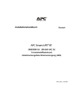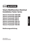
1
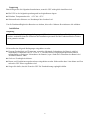
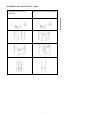
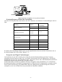
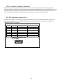
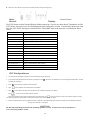
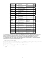
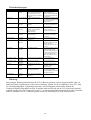
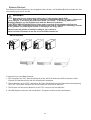
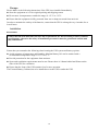
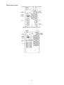
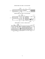
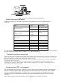
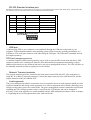
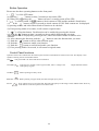
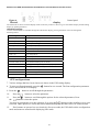
ROLINE ProSecure II
700/1000/1500/2000/3000VA
Standgerät
19”Rack 1HE / 2HE
Bedienungsanleitung
I
BESTIMMUNGEN
IV
WICHTIGER SICHERHEITSHINWEIS
V
SPEZIELLE SYMBOLE
VI
ALLGEMEINE BESCHREIBUNG
1
SYSTEMBESCHREIBUNG
1
ALLGEMEINE BESCHREIBUNG
1
EFFIZIENZ OPTIMIERUNGSFUNKTION
2
FREE-RUN-MODUS
3
DIAGNOSTIK-TESTS
3
SYSTEM KONFIGURATION
3
OPTIONEN
3
SICHERHEITS INFORMATION
5
ANWENDERTÄTIGKEITEN
5
LAGERUNG
6
INSTALLATION
6
RÜCKSEITENANSICHTEN
8
VERBINDUNGEN FÜR STROMVERSORGUNG UND LASTEN
VOREINSTELLUNGEN SEITENS DES HERSTELLERS
11
COMPUTER UND SIGNAL VERBINDUNGEN
11
USV MIT EINEM COMPUTER VERBINDEN
12
RS-232 STANDARD INTERFACE PORT
12
USB PORT
13
EPO PORT (NOT AUS; EMERGENCY POWER OFF)
13
II
10
NETZWERK TRANSIENTEN SCHUTZ
13
BEDIENUNGSLEITFADEN FÜR ANWENDER
14
START UND SHUTDOWN DER USV
14
SHUTDOWN DER USV
14
TASTEN BEDIENUNG
14
KONTROL-PANEL FUNKTIONEN
15
NORMAL-DISPLAY
16
USV KONFIGURATIONEN
16
MANUELLER TEST DER USV
17
ERKLÄRUNG DER USV-MELDUNGEN
18
ALARM ANZEIGEN
18
FEHLERBEHEBUNGEN
19
WARTUNG
19
BATTERIE-WECHSEL
20
BATTERIETAUSCH
20
TECHNISCHE SPEZIFIKATIONEN
I
STANDARDS
II
III
Bestimmungen
FCC Teil 15
Hinweis:
Dieses Gerät wurde getestet und entspricht den Grenzwerten digitaler Class B (700-2000VA) und Class A
(3000VA)-Geräte, gemäß Abschnitt 15 der FCC Regulationen. Diese Grenzwerte bieten angemessenen
Schutz gegen schädliche Interferenz , wenn das Gerät in einer kommerziellen Umgebung betrieben wird.
Dieses Gerät generiert, benutzt und kann Radiofrequenzenergie ausstrahlen, und verursacht, wenn es
nicht gemäß den Bedienungsanweisungen installiert und benutzt wird, schädliche RadiokommunikationsInterferenz. Der Betrieb dieses Geräts in Wohngebieten verursacht wahrscheinlich schädliche Interferenz,
für die der Benutzer auf eigene Kosten Abhilfe schaffen muss.
Gemäss Abschnitt 15 der FCC Bestimmungen, wurde dieses Produkt geprüft und entspricht dadurch den
Vorrausetzungen für Class B (700-2000VA) und Class A (3000VA) bei digitalen Geräten, die geschaffen
wurde um ausreichenden Schutz gegen gefährliche Interferenzen bei Installationen in Wohngebieten zu
gewährleisten.
Installation und Gebrauch der Geräte sollten mit den Anweisungen der Gebrauchsanleitung
übereinstimmen um Interferenzen zu vermeiden die durch Abstrahlenergie des Gerätes erzeugt werden.
Trotzdem kann nicht garantiert werden das nicht eine bestimmte Menge von Interferenzen in einigen
Installationen auftreten können.
Wenn durch Aus- und Wiederanschalten darauf geschlossen werden kann, dass Radio oder TV- Empfang
durch Interferenzen aus diesem Gerät gestört werden, sollte eine der folgenden Maßnahmen getroffen
werden:
l Die Empfangsantenne an einem anderen Ort oder in andere Richtung positionieren
l Entfernung zwischen Empfangsgerät und USV vergrößern
l USV und Empfangsgerät an verschiedene Stromkreise anschließen
l Erfahrenen TV/Radio-Fachmann zu Rate ziehen.
ICES-003
This Class B Interference Causing Equipment meets all requirements of the Canadian Interference
Causing Equipment Regulations ICES–003. Cet appareil numérique de la classe B respecte toutes les
exigences du Reglement sur le matériel brouilleur du Canada.
Declaration of Conformity Request
Units labeled with a CE mark comply with the following standards and directives:
l Harmonic Standards: EN 50091-1-1 and EN 50091-2
l EU Directives:73/23/EEC, Council Directive on equipment designed for use within certain voltage
limits
l 93/68/EEC, Amending Directive 73/23/EEC
l 89/336/EEC, Council Directive relating to electromagnetic compatibility
l 92/31/EEC, Amending Directive 89/336/EEC relating to EMC
The EC Declaration of Conformity is available upon request for products with a CE mark.
IV
Wichtiger Sicherheitshinweis
Bitte diese Hinweise aufbewahren
●
ACHTUNG (USV enthält interne Batterien) Gefahr durch elektrischen Stromschlag.
Auch wenn das Gerät nicht am Stromnetz angeschlossen ist, können im Gerät und den
Ausgangssteckdosen gefährliche Spannungen anliegen.
● ACHTUNG (Keine Benutzerwartung im Geräte-Inneren): Gefahr auf elektrischen
Stromschlag, nicht den Gehäusedeckel abnehmen. Keine Benutzerwartung im GeräteInneren. Service nur durch qualifiziertes Personal.
● ACHTUNG (Kein isolierter Batterieanschluss): Gefahr auf elektrischen Stromschlag, der
Batteriekreis ist nicht vom AC-Eingang isoliert. Zwischen Batterieanschlüssen und Erdung
kann gefährliche Spannung anliegen.
● WARNUNG (Sicherungen): Um der Gefahr von Feuer vorzubeugen, nur Sicherungen des
selben Typs und Wert verwenden.
● WARNUNG: Die USV ist nur zum Gebrauch in trockenen, sauberen Räumen geeignet.
● ACHTUNG: Batterien nicht ins Feuer werfen, Explosionsgefahr.
● ACHTUNG: Batterie nicht öffnen, das austretende Elektrolyt ist gefährlich für Haut und
Augen.
● ACHTUNG: Eine Batterie stellt eine Gefahr auf elektrischen Stromschlag und hohen
Kurzschlussstrom dar.
Vor dem Batteriewechsel sollten folgende Maßnahmen getroffen werden:
-
Ringe , Uhren oder andere Metallgegenstände ablegen.
-
Werkzeug mit isolierten Griffen verwenden.
● Um die Gefahr des elektrischen Stromschlages zu reduzieren, muß die USV von der
Stromversorgung getrennt werden, bevor das Interface-Signalkabel angeschlossen wird. Das
Stromversorgungskabel erst nach dem Verbinden des Signalkabels wieder anschließen.
● Der Batterieservice sollte nur durch qualifiziertes und geschultes Personal erfolgen. Batterien
nicht öffentlich zugänglich lagern.
V
Die Anweisungen dieser Betriebsanleitung werden als wichtig erachtet und sollten während
Inbetriebnahme und laufendem Betrieb immer genau befolgt werden.
ACHTUNG
Das Gerät führt hohe Spannung. Wenn die USV Betriebsanzeige aktiv ist, können die Ausgänge
Spannung führen; auch wenn das Gerät selbst nicht an der Spannungsversorgung
angeschlossen ist.
Vorsicht bei Installation in geschlossenen, temperatur- und feuchtigkeitsgeregelten Räumen, um
der Gefahr von elektrischem Stromschlag vorzubeugen.
Zum Anschluss des Gerätes das mitgelieferte Anschlusskabel verwenden. Das Gerät so
positionieren das die hinteren Anschlüssen gut zugänglich sind.
Alle Servicetätigkeiten an diesem Gerät sollten nur durch qualifiziertes und geschultes Personal
erfolgen.
Bevor irgendwelche Wartungs- oder Instandhaltungs- oder Transporttätigkeiten durchgeführt
werden muss das Gerät komplett ausgeschaltet und abgetrennt werden
Spezielle Symbole
Die folgenden Symbole auf der USV weisen auf Vorsichtsmaßnahmen hin:
GEFAHR DURCH ELEKTRISCHEN STROMSCHLAG – Bitte beachten Sie, dass hier
Gefahr durch elektrischen Stromschlag besteht.
ACHTUNG: BEACHTEN SIE DIE BEDIENUNGSANLEITUNG – Bitte beachten Sie die
Bedienungsanleitung für zusätzliche Informationen.
SICHERER ERDUNGSKONTAKT – Zeigt einen Erdungsanschlusspunkt an.
LAST AN/AUS – Mit diesem Schalter werden die Ausgangssteckdosen und das Anzeigepanel
geschaltet.
RJ-45 ANSCHLUSS – Der Anschluss ist für Netzwerkverbindungen vorgesehen,
Telekommunikationsverbindungen sollten nicht damit verwendet werden.
Die USV oder deren Batterien nur über die entsprechenden Annahmestellen entsorgen, da die
Batterien Blei-Gel enthalten.
VI
Allgemeine Beschreibung
Die Beschreibung in dieser Anleitung beschreibt einphasige USV Systeme im Leistungsbereich 700 –
3000 VA, ihre Grundfunktionen, Betriebsabläufe, und Notfall- Situationen, sowie weiterführende
Informationen zu Versand, Lagerung, Handhabung und Installation der Anlage. Es sind nur detaillierte
Anforderungen der USV beschrieben. Die Installation muss in Übereinstimmung mit diesem Handbuch
erfolgen. Elektrische Installationen müssen ebenso den lokalen Gesetzen und Regelungen entsprechen.
Nur qualifiziertes Personal darf die Anschlussarbeiten durchführen, da Fehlbedienungen sich fatal
auswirken können.
Systembeschreibung
Verschiedene Arten von elektrischen Geräten werden durch die USV (Unterbrechungsfreie
Stromversorgung) geschützt: Computer, Workstations, Prozessregelungssysteme,
Telekommunikationssysteme, Kassensysteme und andere kritische Anlagen. Die Aufgabe einer USV ist
der Schutz der Systeme vor Stromausfall, Strom in schlechter Qualität und damit zusammenhängenden
Problemen.
Elektrische Interferenzen stören in vielen Ausprägungen bei Wechselstrom und erzeugen dort Probleme.
Diese kommen von Beleuchtungen, Störungen bei Stromversorgern, Klimaanlagen und
Fertigungsautomaten. Darum ist Schutz von empfindlichen elektrischen Geräten vor Stromausfall, Überoder Unterspannung, Spannungs- oder Frequenzschwankungen, Transienten und andere Stromstörungen
notwendig.
Damit Spannungsprobleme nicht die kritischen Systeme erreichen und dadurch Schäden an Hardware und
Software durch Fehlfunktionen erzeugen, hilft die USV eine konstante Spannung aufrecht zu erhalten,
sowie die Ausgangsspannung vom restlichen Netz zu trennen.
Allgemeine Beschreibung
Diese USV –Anlage entspricht der Produktnorm
IEC 6240-3 der Class 1 (VFI-SS-111)
Durch Doppelwandlertechnik kann die USV unterbrechungsfreie, saubere einphasige Spannung an Ihre
Systeme liefern, während die Batterien permanent aufgeladen bleiben. Bei einem Spannungsausfall der
länger als die Backup-Zeit der USV dauert, schaltet die USV automatisch ab und vermeidet dadurch
Tiefentladung der Batterien. Wenn die Spannung wiederkehrt startet die USV automatisch wieder an und
beginnt die Wiederaufladung der Batterien.
1
Wie in Bild 1 des Blockdiagramms:
Ein Eingangsfilter reduziert Transienten
Um die volle Batterieladung zu erhalten, wird die Wechselspannung im Gleichrichter gleichgerichtet und
geregelt und aus diesem dann zum Inverter und Konverter geleitet.
Im Inverter wird aus der Gleichspannung wiederum Wechselspannung erzeugt und diese zur Last geleitet.
Während eines Spannungsausfall wird die Leistung aus der Batterie bezogen.
Der Konverter erhöht die Spannung für den Inverter.
Bild.1. Block Diagramm
Effizienz Optimierungsfunktion
Die Effizienz Optimierungsfunktion ist eine neue Eigenschaft die Kosteneffektivität, Minimierung von
Leistungsverlusten und Reduktion des Leistungsverbrauches vereint. Der Wechsel zwischen Bypass- und
ONLINE- Modus wird automatisch und passend zu den Umgebungsbedingungen durchgeführt. ONLINE
-Modus wird bei schlechter werdender Spannungsversorgung verwendet; Bypass Modus bei
kontinuierlicherer Spannungsversorgung. Abweichungen werden in wenigen Sekundenbruchteilen
erkannt und der ONLINE- Modus sofort aktiviert. Rückschalten zum Online-Modus erfolgt wenn die
Eingangsspannung um ±10% abweicht (oder nominal ±15%, selektierbar), wenn die Eingangsfrequenz
um ±3% abweicht oder wenn gar kein Eingang anliegt.
Obwohl Hoch-Effizienz Standard ist, ist der Standard- Betreib der ONLINE Modus. Bypass kann über
das LCD –Panel aktiviert werden, hingegen kann ONLINE- Betrieb auf Wunsch verwendet werden.
2
Free-Run-Modus
Die USV arbeitet im Free-Run-Modus wenn die Eingangsfrequenz außerhalb des selektierten
Eingangsfrequenzbereiches liegt. Free Run mode liegt an, wenn die Ausgangsfrequenz nicht mit der
Eingangsfrequenz übereinstimmt. Beim Start der USV reguliert die USV im Bereich 50 oder 60 Hz
±0.25Hz. Bitte im Kapitel 7.2 des Handbuches für Bypass im Free-Run-Modus nachlesen.
Diagnostik-Tests
Beim Start der USV wird automatisch ein Diagnostik-Test ausgeführt, der Elektronik und Batterien prüft,
sowie Probleme auf dem LCD Display anzeigt.
Ein ‘advanced battery management system’ zeigt ständig den Zustand der Batterien an, und sendet
Vorwarnungen für den Wechsel der Batterien wenn dieser notwendig wird. Weiterhin wird nach 30
Tagen Normalbetrieb, ein Batterie-Entladetest durchgeführt und etwaige Probleme am LCD Display
angezeigt. Bis auf die ersten 24 h nach dem Startup, während die USV im Lademodus ist, können
Diagnostik-Test durchgeführt werden (Seite 7.2).
System Konfiguration
Das System besteht aus dem USV-Gerät und den internen Batterien. Je nach Lokalität und
Lastanforderungen sind einige zusätzliche Optionen als massgeschneiderte Lösungen erhältlich.
Bei der Planung eine USV-Systems sollten die folgende Punkte beachtet werden:
l Die Gesamtlast durch das zu schützende System sollte die Ausgangsleitung (VA) bestimmen. Dazu
sollte etwas Reserve für Erweiterungen und Fehlberechnungen vorgesehen werden.
l Die benötigte Backup Zeit bestimmt die notwendige Größe der Batterie. Wenn die Last geringer ist als
die Nominalleistung der USV ist die effektive Batterielaufzeit höher.
Optionen
Anschluss Möglichkeiten:
•
Relais Karte
•
SNMP/WEB Karte
3
Folgende USV Modelle sind erhältlich
Modell
Backup Zeit mit
Internen Batterien (Volllast)
Aufladezeit auf 90% Kapazität
USV 700VA
5 min
4 Stunden
USV 1000VA
6 min
4 Stunden
USV 1500VA
5 min
4 Stunden
USV 2000VA
6 min
4 Stunden
USV 3000VA
5 min
4 Stunden
Rack 19““
Modell
Backup Zeit mit
Internen Batterien (Volllast)
Aufladezeit auf 90% Kapazität
USV 700VA
5 min
4 Stunden
USV 1000VA
6 min
4 Stunden
USV 1500VA
5 min
4 Stunden
USV 2000VA
6 min
4 Stunden
USV 3000VA
5 min
4 Stunden
4
Sicherheits Information
Die folgenden Informationen sind, zusätzlich zum USV Sicherheitshandbuch,
für alle Anwender lebensnotwendig.
Lagerung und Transport
Bitte mit äußerster Vorsicht behandeln, da in den Batterien hohe Energiedichten enthalten sind. Das Gerät
immer in der auf der Verpackung aufgedruckten Position aufstellen.
Installation
Wenn brennbare Substanzen wie Gase oder Dämpfe vorhanden sind oder der Raum luftdicht verschlossen
ist besteht erhöhte Gefährdung, deswegen sollten dort keine elektrischen Geräte in Betrieb genommen
werden.
Die Instruktionen in diesem Handbuch erläutern wie die USV sicher installiert werden kann. Missachtung
dieser elektrischen Gefährdungspotentiale kann sich fatal auswirken, deswegen sollte dies Handbuch
aufbewahrt werden.
WARNUNG!
Es wird dringend empfohlen das USV- Gehäuse nicht zu öffnen, da die enthaltenen
Komponenten hohe Spannungen führen; deren Berührung könnte sich fatal auswirken. Nur
autorisierte Techniker dürfen dieses Gerät warten.
Die Ausgangsanschlüsse dieser USV führen lebensgefährliche Spannungen, auch wenn das
Gerät nicht am Stromnetz angeschlossen ist.
Anwendertätigkeiten
Die einzigen Tätigkeiten die Anwender durchführen dürfen:
l Ein- und Ausschalten der USV
l Einstellungen auf der Bedieneinheit
l Data-Interface–Kabel anschließen.
All diese Tätigkeiten sollten genau so durchgeführt werden, wie in diesem Handbuch beschrieben.
Höchstmögliche Vorsicht sollte für alle Tätigkeiten vorgenommen werden, Änderungen dabei könnten
sich gefährlich für den Bediener auswirken.
5
Lagerung
Bitte befolgen Sie die folgenden Instruktionen, wenn die USV nicht gleich installiert wird.
l Die USV in der Originalverpackung und im Originalkarton lagern
l Erlaubter Temperaturbereich: +15°C bis +25°C.
l Sicherstellen der Schutzes vor Nassdampf oder feuchter Luft.
Um die Funktionsfähigkeit der Batterien zu erhalten, diese alle 6 Monate für mindestens 8 h aufladen.
Installation
Umgebung
Sicherstellen das alle Umgebungsbedingungen in Übereinstimmung zu diesem Handbuch eingehalten
werden, andernfalls kann die Sicherheit des Installationspersonals und die Funktionalität des Gerätes
nicht garantiert werden.
Sicherstellen das folgende Bedingungen eingehalten werden:
l Extreme Feuchtigkeit und Temperatur vermeiden. Maximale Lebensdauer der Batterie wird bei
empfohlener Temperatur von 15 °C bis 23 °C erreicht. Höhere Umgebungstemperaturen führen
zwangsläufig zu geringerer Lebensdauer der Batterie, bspw. Sinkt die Lebensdauer der Batterie bei
30Grad auf unter 2 Jahre.
l Gerät vor Feuchtigkeit schützen.
l Raum- und Ventilationsvorgaben müssen eingehalten werden. Sicherstellen dass 10cm hinter und 5cm
neben der USV Platz vorgehalten wird.
l Sorgen Sie dafür, dass die Front der USV für Frontbedienung zugänglich bleibt.
6
Installation der Rack-Mount Typen
Installation mit unteren
Schienen.
Installation mit hinterem Bügel
.
7
Rückseitenansichten
8
9
Verbindungen für Stromversorgung und Lasten
Die folgenden Ein- und Ausgangskabel werden bei allen Modellen mitgeliefert:
700 VA, 1000 VA,
1500 VA, 2000 VA
3000 VA
Ein IEC 320 10 A (Eingangskabel)
Zwei IEC 320 10 A (Ausgangskabel)
Ein IEC 320 16 A (Eingangskabel)
Zwei -IEC 320 10 A (Ausgangskabel)
l Verbinden Sie das Eingangskabel der USV mit einer geerdeten Steckdose. Die Batterien werden
automatisch geladen, wenn das Gerät an der Stromversorgung angeschlossen ist. Bitte beachten Sie,
dass die maximale Backup-Zeit bei sofortigem Start des Gerätes nicht zur Verfügung steht weil die
Batterien min. 8 h vor dem ersten Gebrauch aufgeladen werden müssen.
l Wenn das Gerät einen “Site Wiring Fault” (Verkabelungsfehler) zeigt, stecken Sie den Schukostecker
um 180° gedreht ein (Kapitel 7.4)
l Nach dem Aufladen der Batterien können die Lasten angeschlossen werden. (Fig. 3)
l Keine Geräte anschließen, die möglicherweise die USV überlasten oder solche die gerichteten
Halbwellenstrom ziehen, wie Haartrockner oder Staubsauger.
l Sollen Computer oder Alarmanlagen verwendet werden, müssen die Anschlüsse anhand Kapitel 6 des
Handbuches vorgenommen werden.
l Die Installation ist jetzt fertiggestellt.
.
10
Fig. 3 Beispiel der Installation von Plug & Play Produkten
Voreinstellungen seitens des Herstellers
Auf dem LCD Display findet man mehrere der USV Parameter zur Selektion. Voreinstelllungen sind wie
folgt:
Einstellung
Ausgangs- Spannung
Selektion
HerstellerVoreinstellung
208/220/230/240 Vac 230V
±10%
Eingang/Bypass Spannung
+10/-15%
+10/-15%
+15/-20%
±2%
Eingang/Frequenz
±5%
±5%
±7%
Hoch Effizienz Modus
An/Aus
Aus
Free Run Modus
An/Aus
An
Bypass An/Aus bei FreeRun Modus
An/Aus
Aus
Akust.Alarm-Signal deaktivieren
An/Aus
Aus
Verkabelungsfehler-Alarm
An/Aus
Aus
Externes Batterie Pack
0, 1, 2
0
Sie können die Einstellungen ändern, aber es wird empfohlen dass dies nur nach der Installation und vor
der Inbetriebnahme der Last erfolgt. (Kapitel 7.2)
Computer und Signal Verbindungen
Auf der Rückseite der USV befindet sich ein Interface das die Kommunikation mit dem Computer
ermöglicht; dessen Position ist über Fig. 2 zu finden. Dort befindet sich ein USB-Interface, eine RS232
Schnittstelle und eine Not-Aus-Schnittstelle (EPO,. Emergency Power Off). USB Schnittstelle und RS232
Schnittstelle können nicht gleichzeitig verwendet werden.
Zusätzlich befindet sich dort ein optionaler Interface-Steckplatz, der die Installation von verschiedenen
Kommunikationskarten ermöglicht. Er kann parallel zu USB oder RS232-Schnittstelle verwendet werden.
Derzeit sind herstellerseitig eine SNMP/WEB- Karte die Management und Monitoring über Netzwerk
ermöglicht, sowie eine AS/400 Karte mit potentialfreien Kontakten erhältlich.
11
USV mit einem Computer verbinden
Das Kommunikationsschnittstelle für die USV und den PC wird komplett mit PowermanagementSoftware geliefert. Nur über das mitgelieferte Kommunikationskabel kann die Verbindung zum PC über
den RS232 Port hergestellt werden. Stellen Sie auch sicher, dass das Betriebssystem des PC auch von
dieser Software unterstützt wird. Die Hinweise der Software helfen bei der Installation.
RS-232 Standard Interface Port
Das RS-232 Interface verwendet eine 9pol. SUB-D Buchse. Die Information besteht aus Daten über
Spannungsversorgung, Last und USV. Die Interface Port-Kontakte und ihre Funktion sind aus der
folgenden Tabelle zu ersehen.
Pin #
Signal Name
Richtung (re USV)
Funktion
2
TxD
Output
TxD Output
3
RxD
Input
RxD / Inverter Off Input
5
Common
6
CTS
Output
Ac Fail Output
8
DCD
Output
Low Battery Output
9
RI
Output
+8-24 VDC Power
Common
Achtung! Maximaler Wert
24Vdc/50mA
12
USB Port
Sie können die USV auch über den USB-Port mit der USB Schnittstelle des Computers verbinden. USB
standardisierte Hard- und Software sowie installierte USB Treiber sind Vorraussetzung für die
Verbindung. Der RS232-Port kann nicht gleichzeitig zum USB-Port verwendet werden. Das USBKabel ist standardisiert und kann separat bezogen werden.
EPO Port (NOT AUS; Emergency Power Off)
Ein kundenspezifischer Schalter (Öffner) kann verwendet werden um die EPO- Verbindung der USV zu
öffnen und damit die Ausgänge der USV abzuschalten. Da der EPO- Schalter die Ausgänge hart
abschaltet, kommen keine ‚shutdown’ Abläufe der Management Software mehr zur Auswirkung. Die
USV muss manuell wieder gestartet werden um wieder Spannung an die Ausgänge zu bekommen.
Netzwerk Transienten Schutz
Der Netzwerk-Überspannungs-Schutz auf der Rückseite des Gerätes hat Ein- und Ausgang als RJ45
Buchse (10BaseT). Verbinden Sie den Eingangsstecker mit der als IN bezeichneten Buchse und den
Ausgangsstecker mit der als OUT bezeichneten Buchse ihres Netzwerk-Anschlusses.
6.2 Last Segmente (700 - 3000 VA)
Die Power Management Software steuert die Steckdosengruppen (Lastsegmente), die geordneten
‚shutdown’ und ‚startup’ der Geräte ermöglichen. Weniger kritische Geräte können dann während eines
Stromausfalls eher ausgeschaltet werden um Batteriekapazität für kritische Lasten zu sparen. Näheres im
Manual zur Powermanagement Software. Der Lastgruppenstatus kann über das LCD Display überwacht
und gesteuert werden. Die Lastsegmente werden normalerweise über die Powermanagement Software
gesteuert. (Kapitel 5.2 für die zwei Lastsegmente)
13
Bedienungsleitfaden für Anwender
Dieses Kapitel enthält notwendige Informationen über die Funktionsweise des Gerätes.
Normalerweise arbeitet die USV automatisch, aber für einige Zustände wie z.B. kurz nach
Installation ist das ,Start’ und ‚Shutdown’ -Verfahren hier beschrieben.
Start und Shutdown der USV
Start der USV
l Vergewissern Sie sich das die Installation der USV korrekt ist und das Eingangskabel an einer gut geerdeten Anschlussdose
angeschlossen ist.
l Die USV kann durch betätigen des
Knopfes am Frontpanel gestartet werden.
l Die USV wird jetzt ihre Tests durchlaufen: interne Funktion, Hauptsynchronisation und Inverter Startup. Danach wird Spannung an die
Ausgangsdosen geleitet
l Nach diesem Tests wird die USV auf dem Panel “Ready on” anzeigen. Die LED wird aufleuchten wenn Ausgangs-Spannung anliegt und
das LCD Display wird “Line mode” anzeigen.
l Angeschlossene Last einschalten.
Shutdown der USV
l Herunterfahren und abschalten der angeschlossenen Lasten.
l Drücken des
Knopfes am Frontpanel für fünf Sekunden. Das Signal ertönt und die USV beginnt das ‚shutdown’.
l Das LCD Display zeigt ‚UPS OFF’ für ein paar Sekunden.
l In Notfällen sollte der EPO-(Not-Aus)-Kontakt an der Rückseite des Gerätes verwendet werden.
Tasten Bedienung
l Am Frontpanel befinden sich drei Bedienungstaster:
l 1. “
” ist ein EIN / AUS Taster :
l a). Drücken des ”
” Tasters (min. 3 Sekunden) zum Anschalten derUSV.
l (b). Wenn die USV arbeitet, drückt man den “
2.“
” Taster (min 3 Sekunden) um die USV auszuschalten.
” ist der Enter Taster. Mit diesem Taster wird der Zustand der USV anhand folgender Liste geprüft:
l (a). Drücken des “
” Tasters (min. 2 Sekunden) um den Zustand der USV zu ermitteln.
Jeder Wert kann durch einmaliges drücken des Tasters angezeigt werden, 15 Funktionswerte können abgerufen werden.
l (b) 10 Sekunden nach dem letzten Tasterdruck springt die USV wieder auf die Hauptanzeige.
l 3.
ist ein Funktionstaster . Alle Funktion können über Druck auf diesen Taster aktiviert werden.
l (a). Drücken des
” Taster (min 2 Sekunden) zur Wahl der gewünschten Funktion.
l Jeder Wert kann durch einmaliges Drücken angewählt werden, 14 Funktionswerte können angezeigt werden.
l (b). Nach Funktionswahl drücken des “
” Taster zur Aktivieren der gewünschten Funktion.
l (c). Drücken des “
” Taster für weitere Funktionsauswahl.
l (d). Drücken des “
” Taster zu Funktionsanwahl.
l (e). Drücken des “ ” Taster zum Bestätigen und Aktivieren der Funktion.
l (f). Nach 10 Sekunden ohne Tastenbetätigung springt das LCD-Panel wieder zurück.
14
Kontrol-Panel Funktionen
l Die Funktion der USV wird auf dem Anzeigepanel mit 5 LED und einem LCD Screen angezeigt. Das Anzeigemodul kann auch
akustische Signale absetzen.
l ON/
Die grüne LED leuchtet bei als Betriebsanzeige der USV.
l ON-LINE/
leuchtet grün.
Wenn die USV im Normal oder statischem Bypass Modus ist, führen die Ausgänge Spannung und diese LED
l
ON-BAT/
USV im Batteriemodus.
l BYPASS/
USV im Bypass Modus, die LED leuchtet gelb.
l FAULT/
Bei internem Fehler in der USV, leuchtet dieses LED in rot und ein akustischer Alarm ertönt. Zum Abstellen
des Alarmtones irgend einen der Frontpanel-Taster drücken.
15
l Status der USV, Messwerte und Alarm werden auf dem LCD Screen angezeigt.
Kontroll-Panel
Bild 6.
Normal-
Display
Der USV Status wird im Normal-Display Modus angezeigt. Von hier aus kann durch Tastendruck auf die
USV Werte-Anzeigen sowie die Einstellungsanzeigen zugegriffen werden. Verschiedene Messwerte sind
über die USV-Werte-Anzeigen ersichtlich; über Tastendruck kann man durch die verschiedenen Werte
rollen:
LCD Anzeige
Beschreibung
O/P VOLT= xxx, xV
Anzeige: Ausgang AC Spannung
O/P FREQ= xx, x Hz
Anzeige: Ausgangs-Frequenz
I/P VOL T= xxx, xV
Anzeige: Eingang AC Spannung
I/P FREQ= xx, x Hz
Anzeige: Eingangs-Frequenz
BAT VOLT= xx,xV
Anzeige: Batterie-Spannung
O/P LOAD%= xx%
Anzeige: Last: % der max. Last
O/P W= xW
Anzeige: Ausgang in Watt
O/P VA= xVA
Anzeige: Ausgang in VA
O/P CURR= xA
Anzeige: Ausgang Strom
BACKUP TIME= xx min Anzeige: Geschätzte Backup Zeit in Minuten
BAT CHARG= xx%
Anzeige: Geschätzte Batterieladung in %
TEMPERATURE= xxC
Anzeige: Ermittelte Umgebungstemperatur
BAT PACK NUM= x
Anzeige: Externe Batterie-Pack-Number
RATING = xxxxVA
Anzeige: USV Auslastung
CPU VERSION xx.x
Anzeige: CPU Version
USV Konfigurationen
1. Verschiedene Einstellungen werden im USV Einstellungs-Display angezeigt.
2. Um in den Konfigurationsmodus zu kommen, drücken Sie den
LCD Display angezeigt.
3. Den
4. Den
5. Den
Den
Taster für eine Sekunde. Der erste Konfigurationsparameter wird am
Taster drücken zum Rollen der Parameter.
Taster drücken um den Parameter anzuwählen.
Taster drücken um durch die Optionen für die selektierten Parameter zu Rollen
Taster für die gewählte Option drücken
Wenn zum Speichern der Selektion aufgefordert wird, kann durch den
Taster gespeichert werden. Die anderen Optionen werden
automatisch gespeichert und gestartet. In der unteren Tabelle sind weitere Details zu sehen.
6. Wenn 10 Sekunden keine Tasten gedrückt wurden, beendet die USV das Konfigurationsmenue und kehrt zum Normalbetrieb zurück.
Anzeige im LCD-Panel : Line Mode.
ACHTUNG!
Die Herstellereinstellungen müssen nicht unbedingt geändert werden, sie können aber auf ein spezifiziertes
USV-System hin geändert werden.
16
Einstellungen
LCD
Display
Beschreibung
Selektion
Voreinstellung
Output Spannung
O/P V
Setting
Nominal Spannung
208/220/230/240 V
230V
Input/Frequenz
I/P F Setting
Input/Bypass
Spannung
I/P Bypass
Set
Free Run Modus
Free Run
Set
Bypass
Enable/Disable at
Free run mode
Bypass
disable
HE Modus
HE Mode
Set
Force Manual
Bypass
Manual
bypass
Management der
Lastgruppen
Outlet
Setting
Batterie Test
Battery Test Batteriezustandstest
Lautlos Funktion
Silence Set
Anzahl der
Externen Batterie
Packs
Einstellung benötigt für
Bat Cabinet
Laufzeitberechnung
Set
Verdrahtungsfehler Site Fault
Alarm
Set
±2%
Input-Frequenz-Bereich für
±5%
USV im Free Run Modus
±7%
±10%
Input-Spannungs-Bereich
+10/-15%
wenn Bypass aktiv ist.
+15/-20%
Wenn die USV im Free Run
Modus (unsynchroniziert) ON/OFF
laufen darf
Wenn Enable gewählt ist,
geht die USV auf Bypass
Disable/Enable
(unsynchroniziert.)
USV läuft im HochON/OFF
Effizienz-Modus
USV läuft dauerhaft im
ON/OFF
Bypass-Modus
. Nur für Service**
1 ON & 2 ON
Zwei Lastsegmente können
1 OFF & 2 ON
über das Panel gesteuert
1OFF & 2 OFF
werden
1 ON & 2 OFF
Enable oder disable der
Lautlos-Funktion
±5%
+10/-15%
ON
Disable
OFF
OFF
Beide Last
segmente
ON
ON/OFF
OFF
0 (nur interne Batterien)
1(ein externes Gehäuse)
2 (zwei externe Gehäuse)
0
Enable oder disable für
Verdrahtungsfehler-Alarm
Enable /Disable
Disable
English
Sprachwahl
Language
Sprachauswahl
English, Deutsch, Franz.,
Spanisch, Italienisch..
Generator Modus
Generator
Generator Modus ***
ON/OFF
OFF
Set RS232
communication
RS232
Control
RS232 Kommunikation
enable oder disable
Enable/Disable
Enable
**) Anmerkung: Damit die USV und die Power Management Software ordnungsgemäß funktionieren,
sollte die Einstellung ‚manueller Bypass’ auf OFF stehen da sonst die angeschlossene Last nicht
geschützt ist. Die Einstellung ist für den Einsatz mit externem Wartungs- Bypass vorgesehen.
***) Anmerkung: Die USV-Anlage sollte ausgeschaltet und mit anliegender AC-Spannung gehalten
werden bevor die Generator-Funktion aktiviert wird.
Manueller Test der USV
Manuelle Tests können sowohl für die USV als auch für die Batterien durchgeführt werden, auch währen
des Ladezustandes. Sie erreichen dies über das Konfigurationsmenue.
Manueller Batterie Test:
In den Parametern rollen bis ‘Manual Bat Test’ auf LCD erscheint.
Den
Taster zweimal drücken
17
Erklärung der USV-Meldungen
Die hier beschriebenen Fehlerbehebungsmaßnahmen geben einfache Hinweise auf USV-Störungen.
Nach Erkennen von Alarmanzeigen auf dem Kontrollpanel sollten die Fehlerbehebungs- maßnahmen
eingeleitet werden.
Alarm Anzeigen
Die USV erzeugt folgende Alarmsignale:
l Wenn die USV auf Batteriebetrieb ist und das ON BATTERY LED leuchtet, piept die USV alle 5
Sekunden
l Wenn die USV im Bypass-Modus läuft und das BYPASSED LED leuchtet, gibt die USV kein
Tonsignal von sich.
l Wenn die USV einen internen Fehler hat und das ALARM LED leuchtet, gibt die USV einen
konstanten akustischen Alarm ab, und zeigt die Fehlerursache auf dem Display an.
Alarm Stummschalten
l Durch betätigen irgendeines der drei Taster auf dem Front-Panel, kann das Alarmsignal abgestellt
werden, außer bei Batterieunterspannung, die den Alarm erneut ertönen lässt..
l Am LCD Display kann auch lautloser Alarm eingestellt werden, so daß bei keiner Funktionsstörung
akustisch gewarnt wird.
l
Hiervon wird aber dringend abgeraten.
18
Fehlerbehebungen
Anzeige am LCD
Output Overload
Battery Test
Akust. Alarm
Zwei Piep pro
Sekunde
Alarm Beschreibung
Die UPS ist überlastet (im Line
Modus). Die Geräte brauchen
mehr Leistung als die USV
liefern kann. Die USV arbeitet
im Bypass.
Kein Tonsignal. Die USV führt Batterietest
durch.
Over-Charge
Konstanter
Alarmton
Batterien sind
überladen.
Low Battery
2 Töne alle 5
Sekunden
On-Battery
Ein Ton alle 5
Sekunden
Die USV arbeitet auf Batterie
und wird gleich abschalten
wegen zu geringer
Batteriespannung
Die USV arbeitet auf
Batteriespannung.
Charger Failure
Konstanter
Alarmton
Konstanter
Alarmton
Over-Temperature
Output Short
Konstanter
Alarmton
High output Voltage
Konstanter
Alarmton
Konstanter
Alarmton
2 Töne pro
Sekunde
Low Output Voltage
Bus Fault
Fehler im BatterieLadesegment.
Überhöhte Temperatur.
Behebungsmassnahmen
Weniger wichtige Geräte auf
anderen Stromkreisen
betreiben. danach, schaltet die
USV automatisch zurück auf
Normalbetrieb.
Keine Aktion erforderlich. Die
USV zurück auf Normalbetrieb
wenn der Batterietest
erfolgreich war.
Geschützte Lasten ausschalten.
USV abschalten und Service
benachrichtigen.
Die USV wird wiederanlaufen
wenn ausreichende
Netzspannung zurückkehrt.
Offene Dateien schliessen und
kontrollierten‚ ‚shut down’
durchführen..
Service benachrichtigen.
Überprüfen ob Ventilatoren
und Lüftungsöffnungen nicht
verdeckt sind, und
Umgebungstemperatur nicht
über 40°C.
Ausgangskurzschluss
Alle Lasten abziehen und USV
erneut einschalten. Wenn
dadurch der Fehler behoben ist
hat eines der angeschlossenen
Geräte einen Defekt. Falls
Fehler nicht behoben Service
benachrichtigen
Ausgangsspannungsüberhöhung Service benachrichtigen
Ausgangsunterspannung
Service benachrichtigen
Überhöhte interne DC-Bus
Spannung e.
Geschütze Lasten und USV
abschalten . Service
benachrichtigen
USV ohne Erdung installiert.
USV-Spannungsvlarität
falsch:Verbindungsstecker um
180° drehen (Schuko).
Site wiring Fault
1 Ton pro
Sekunde
Spannungsdifferenz zwischen
Masse und Erdpotential
Line abnormal
1 Ton pro
Sekunde
Falsche AC Leitung während
Auto-Restart
Wartung
Mit geringem Wartungsaufwand kann die USV in Betrieb gehalten werden. Gegebenenfalls sollte ein
Batteriewechsel vorgenommen werden. Die kritischsten Aspekte für die Verfügbarkeit einer USV sind
die Umweltbedingungen. Umgebungstemperatur- und Feuchtigkeit sollten immer anhand der
Gerätespezifikation eingehalten werden; weiterhin sollte der Bereich um die USV sauber und staubfrei
gehalten werden. Bei einer Temperatur von 23°C, ist die typische Batterielebensdauer 4 Jahre. Ebenfalls
sollte in Abständen von 6-12 Monate geprüft werden ob die Backup-Zeit noch ausreichend ist.
19
Batterie-Wechsel
Die Batterien können dank dem‚ hot-swappable battery feature’ im laufenden Betrieb und ohne die Last
abzuschalten gewechselt werden.
WARNUNG!
Batterien können elektrischen Schlag oder Verbrennungen durch hohe
Kurzschlussströme verursachen. Bitte die folgenden Schutzmaßnahmen vorsehen: 1. Ringe und
Uhren ablegen. 2. Werkzeug mit isolierten Griffen verwenden. 3. Werkzeug und andere
Metallgegenstände von den Schaltkreisen und den Batterien fernhalten.
ELECTRISCHER STROMSCHLAG. Bitte nicht versuchen die Beschaltung an Batterien,
Verkabelung oder Verbindungssteckern zu ändern oder neu zu verdrahten. Änderungsversuche
in der genanten Art können gravierende Verletzungen zur Folge haben.
Batterien nur mit gleicher Anzahl des richtigen Typs tauschen.
Batterien nicht freischalten wenn das Gerät im Batteriemodus ist.
Batterietausch
Vorgehensweise beim Batterietausch:
1. Das Frontpanel der USV kann durch Druck an den mit Pfeil markierten Stellen entfernt werden.
Danach die Schrauben lösen und den Metalldeckel abnehmen.
2. Batteriekassette aus der USV entnehmen. Bei allen Modellen beträgt die Batteriekassettenspannung
max. 48V. Nach dem Abziehen der Stecker Batterien der Kassette tauschen.
3. Die Kassette mit den neuen Batterien in die USV einsetzen und Anschließen.
4. Metallfrontplatte aufsetzen und anschrauben. Frontpanel aufsetzen und festschrauben .
20
Technische Spezifikationen
Leistungsbereich 700-3000 VA (230V)
Allgemein
Nennleistung
700VA, 1000 VA, 1500 VA, 2000 VA, 3000 VA bei Pf 0.7
Technologie
On-line, Doppelwandler Technologie mit automatischem Bypass
EINGANG
Phase
Eine Phase mit Erdung
Bypass Spannung:
184-265 VAC (wählbar)
Eingangs-Spannungsbereich:
120/140/160 VAC-276 VAC
Frequenz:
50/60 Hz. Automatische Erkennung
Fre0quenzabweichungsbereich
45-65 Hz
Synchronization window
± 3Hz.
Eingangsstrom
700 VA 3A, 1000 VA 4A,
1500 VA 5.7A, 2000 VA 7.7A, 3000 VA 12A
Eingangs Leistungsfaktor: 0.97
AUSGANG
Ausgangsspannung: 208/220/230/240 VAC, über LCD Panel wählbar
Spannungsregelung: ± 2%
Spannungsverzerrung: < 5% THD bei nicht linearer Last, < 3% THD bei linearer Last
Frequenzregelung:
± 0.25 Hz (Batterie- oder Free Run-Modus)
Dynamik :
± 9 % max. von 100% bis 20 % oder von 20% bis 100 % lineare Last
Überlastkapazität:
100-125% 1 min, 125-150% 10 sec
Wirkungsgrad:
größer 86%
Leistungsbereich 700-3000 VA (19” Rack-Mount Modell)
Allgemein
Nennleistung
700VA, 1000 VA, 1500 VA, 2000 VA, 3000 VA bei p.f 0.7
Technologie
On-line, Doppelwandler Topologie mit automatischem Bypass
EINGANG
Phase
Eine Phase mit Erdung
Bypass Spannung:
184-265 VAC (wählbar)
Eingangs-Spannungsbereich:
120/140/160 VAC-276 VAC
Frequenz:
50/60 Hz. Automatische Erkennung
Frequenzabweichungsbereich
45-65 Hz
Synchronisationsbereich
± 3Hz.
Eingangsstrom
700 VA 3A, 1000 VA 4A,
1500 VA 5.7A, 2000 VA 7.7A, 3000 VA 12A
Eingangs Leistungsfaktor: 0.97
AUSGANG
Ausgangsspannung: 208/220/230/240 VAC, über LCD Panel wählbar
Spannungsregelung: ± 2%
Spannungsverzerrung: < 5% THD bei nicht linearer Last, < 3% THD bei linearer Last
Frequenzregelung:
± 0.25 Hz (Batterie- oder Free Run-Modus)
Dynamik :
± 9 % max. von 100% bis 20 % oder von 20% bis 100 % lineare Last
Überlastkapazität:
100-125% 1 min, 125-150% 10 sec
Wirkungsgrad:
größer 86%
Umgebung
Umgebungstemperatur:+0 °C to +35 °C
Empfohlene Temperatur:
+15 °C to +25 °C
Lagertemperatur:
-15 °C to +50 °C
Kühlung:
Aktive Kühlung
Feuchtigkeit:
0-95%, nicht kondensierend
Geräuschemission:
< 45 db Normal und Batterie-Modus (700-1000 VA)
< 50 db Normal und Batterie-Modus (1500-3000 VA)
STANDARDS
l Sicherheit:
EN50091-1-1
l Emissionen:
EN50091-2 class B
l Störsicherheit:
EN50091-2
230V Modell
AusgangsLeistung
700VA/490 W
1000VA/700W
1500VA/1050W 2000VA/1400W 3000VA/2100W
Anschluss
Eingang
IEC 320 (10A)
IEC 320 (10A)
IEC 320 (10A)
IEC 320 (10A)
Anschluss
Ausgang
4 x IEC 320
C14(10A)
4 x IEC 320
C14(10A)
4 x IEC 320
C14(10A)
8 x IEC 320
C14(10A), 1 x
IEC 320 (16A)
Batterietyp
Blei-Gel
7.2Ah/12V
Blei-Gel
7.2Ah/12V
Blei-Gel
Blei-Gel 9Ah/12V 7.2Ah/12V
Blei-Gel 9Ah/12V
3
3
6
Anzahl Batterien 2
Backup Zeit/Voll
Last
5 min
Ladezeit
6
IEC 320 (16A)
8 x IEC 320
C14(10A), 1 x
IEC 320
C20(16A)
6 min
5 min
6 min
5 min
<4 Stunden
<4 Stunden
<4 Stunden
<4 Stunden
<4 Stunden
auf 90%
auf 90%
auf 90%
auf 90%
auf 90%
19” Rack-Mount Modell
Ausgangs
leistung
AnschlußEingang
AnschlußAusgang
700VA/490 W
1000VA/700W 1500VA/1050W 2000VA/1400W 3000VA/2100W
4 x IEC 320
C14(10A)
Blei-Gel
7.2Ah/12V
4 x IEC 320
C14(10A))
Blei-Gel
7.2Ah/12V
4 x IEC 320
C14(10A)
Blei-Gel
9Ah/12V
4 x IEC 320
C14(10A)
Blei-Gel
7.2Ah/12V
4 x IEC 320
C14(10A)
Blei-Gel
9Ah/12V
2
3
3
6
6
5 min
6 min
5 min
6 min
5 min
<4 Stunden auf
90%
<4 Stunden auf
90%
<4 Stunden auf
90%
<4 Stunden auf
90%
<4 Stunden auf
90%
Abmessung
B x T x H 428 x 425 x 84
mm
428 x 425 x 84
428 x 425 x 84
428 x 610 x 84
428 x 610 x 84
17.3
18.1
31.6
33
Batterietyp
Anzahl
Batterien
Backup
zeit/Vollast
Ladezeit
Gewicht kg
14.6
ProSecure II
700 VA - 3000 VA UPS
User’s and Installation Manual
.
IV
INTRODUCTION
7
SYSTEM DESCRIPTION
7
FREE RUN MODE
9
DIAGNOSTIC TESTS
9
SYSTEM CONFIGURATION
10
SAFETY INFORMATION
11
STORAGE
12
INSTALLATION
12
REAR PANEL VIEWS
14
CONNECTION TO MAINS AND LOADS
16
DEFAULT SETTINGS AT THE FACTORY
17
COMPUTER AND ALARM CONNECTIONS
17
CONNECTING THE UPS TO A COMPUTER
17
RS-232 STANDARD INTERFACE PORT
18
USB PORT
18
NETWORK TRANSIENT PROTECTOR
18
LOAD SEGMENTS
18
USER’S GUIDE TO OPERATIONS
19
STARTING AND SHUTTING DOWN THE UPS
19
BUTTON OPERATION
20
CONTROL PANEL FUNCTIONS
20
1
NORMAL DISPLAY
21
UPS CONFIGURATIONS
21
MANUAL TEST OF THE UPS
23
INTERPRETING UPS MESSAGES
23
TROUBLE SHOOTING
24
MAINTENANCE
25
REPLACING BATTERIES
25
TECHNICAL SPECIFICATIONS
26
STANDARDS
27
2
NOTICE: Pursuant to section 15 of the FCC rules, this product has been tested and thereby complies to the conditions of a
Class B (700-2000VA) and Class A (3000VA) digital device, which have been established for offering sufficient protection
against dangerous interference for installation in a residential area. Installation and use of the equipment should comply with
the instructions provided in order to avoid such interference due to the amount of radio frequency energy that is radiated and
generated by the equipment. In spite of this, we cannot assure that a certain amount of interference may not occur in some
installations. If, by turning on and off, it can be deduced that your radio or television reception is found to be influenced by
harmful interference from the equipment, it is recommended to use one of the following preventive measures:
l Place the receiving antenna in a separate location or orientation.
l Ensure a greater distance is achieved between the receiver and the equipment.
l Ensure that your equipment is connected to an outlet on a separate circuit than the receiver.
l Contact a technician experienced with radio and TV or a dealer for further assistance.
This Class B Interference Causing Equipment meets all requirements of the Canadian Interference Causing Equipment
Regulations ICES–003. Cet appareil numérique de la classe B respecte toutes les exigences du Reglement sur le matériel
brouilleur du Canada.
Declaration of Conformity Request
Units labeled with a CE mark comply with the following standards and directives:
l Harmonic Standards: EN 50091-1-1 and EN 50091-2
l EU Directives:73/23/EEC, Council Directive on equipment designed for use within certain voltage limits
93/68/EEC, Amending Directive 73/23/EEC
89/336/EEC, Council Directive relating to electromagnetic compatibility
92/31/EEC, Amending Directive 89/336/EEC relating to EMC
The EC Declaration of Conformity is available upon request for products with a CE mark.
3
IMPORTANT SAFETY INSTRUCTIONS
SAVE THESE INSTRUCTIONS
● CAUTION (UPS Having Internal Batteries): Risk of electric shock - Hazardous live parts inside this unit are
energized from the battery supply even when the input AC power is disconnected.
● CAUTION (No User serviceable Parts): Risk of electric shock, do not remove cover. No user serviceable parts
inside. Refer servicing to qualified service personnel.
● CAUTION (Non-isolated Battery supply): Risk of electric shock, battery circuit is not isolated from AC input,
hazardous voltage may exist between battery terminals and ground. Test before touching.
● WARNING (Fuses): To reduce the risk of fire, replace only with the same type and rating of fuse.
● WARNING: Intend for installation in a controlled environment.
● CAUTION: Do not dispose of batteries in a fire, the battery may explode.
● CAUTION: Do not open or mutilate the battery, released electrolyte is harmful to the skin and eyes.
● CAUTION: A battery can present a risk of electric shock and high short circuit current. The following
precaution should be observed when working on batteries
Remove watches, rings or other metal objects.
Use tools with insulated handles.
● To reduce the risk of electric shock, disconnect the UPS from the mains supply before installing a computer
interface signal cable. Reconnect the powers cord only after signaling interconnections have been
made.Servicing of batteries should be performed or supervised by personnel knowledge of batteries and the
required precautions. Keep unauthorized personnel away from batteries.
4
The instructions contained within this safety manual are deemed important and should be closely
followed at all times during installation and follow-up maintenance of the UPS and batteries.
CAUTION
The unit has a dangerous amount of voltage. If the UPS indicator is on, the unit’s outlets may
have a dangerous
amount of voltage even when not plugged into the wall outlet because the battery may continue
to supply power.
Care should be taken to undertake installation indoors free from electrically-conductive
particles which is under temperature and humidity control in order to reduce
the risk of electric shock.
It is best to disconnect the device using the power supply cord. Ensure that the equipment is
placed in a position near
the outlet where easily accessible.
Except replacing the batteries, all servicing on this equipment must be carried out by qualified
service personnel.
Before conducting any maintenance, repair or shipment, first ensure that everything is turned
off completely and disconnected.
For additional safety instructions, please use the Safety Manual as reference.
5
Special Symbols
The following symbols used on the UPS warn you of precautions:
RISK OF ELECTRIC SHOCK – Please observe the warning that a risk of electric shock is
present.
CAUTION: REFER TO OPERATOR’S MANUAL - Refer to the operator’s manual for
additional information, such as important operating and maintenance instructions.
SAFE GROUNDING TERMINAL - Indicates primary safe ground
LOAD ON/OFF - Pressing this button turns on/off the outputreceptacles and the Indicator light.
RJ-45 RECEPTACLE - The receptacle provides network interface connections and telephone or
telecommunications equipment should not be plugged into it.
Please do not discard the UPS or UPS batteries as the UPS may have valve regulated, lead–acid
batteries. Please recycle batteries.
The instructions contained within this safety manual are deemed important and should be closely
followed at all times during installation and follow-up maintenance of the UPS and batteries.
6
Introduction
The information provided in this manual covers single phase 700 – 3000 VA, uninterruptible power
systems, their basic functions, operating procedures, and emergency situations, also including information
on how to ship, store, handle and install the equipment. Only detailed requirements of the UPS units are
described herein, and installation must be carried out in accordance with this manual. Electrical
installations must also carefully follow local legislation and regulations. Only qualified personnel should
conduct these installations as failure to acknowledge electrical hazards could prove to be fatal.
System description
Several different kinds of sensitive electrical equipment stay protected by a UPS (Uninterruptible Power
System) including computers, workstations, process control systems, telecommunications systems, sales
terminals, other critical instrumentation, etc. The purpose of the UPS is to protect these systems from
poor quality utility power, complete loss of power, or other associated problems.
Electrical interference abounds in many forms causing problems in AC power, from lightning, power
company accidents and radio transmissions to motors, air conditioners, and vending machines, among
others. So protection of sensitive electrical equipment is vital to protect against power outages, low or
high voltage, slow voltage fluctuations, frequency variations, differential and common-mode noises,
transients, etc.
In order to prevent power line problems reaching critical systems causing damage to software, hardware
and causing equipment to malfunction, the UPS helps by maintaining constant voltage, isolating critical
load output if needed, and cleaning the utility AC power.
7
General description
As a double conversion on-line UPS, it is able to supply uninterrupted, clean single-phase power to your
critical systems while keeping batteries charged continuously, regardless of whether utility power fails or
not.
In event that a power failure lasts longer than a UPS backup time, it will shut down avoiding battery
discharge, and as soon as voltage comes back, the UPS will automatically charge up and start recharging
the batteries.
As shown in fig.1 block diagram:
l An input filter reduces transients on the mains
l For maintaining full battery charge, AC-power is rectified and regulated in the rectifier feeding power
to the inverter and battery converter.
l DC power is converted to AC in the inverter passing it on to the load.
l Power is maintained from the battery during a power failure.
l The converter increases voltage appropriately for the inverter.
Fig.1. Block diagram
The Efficiency Optimizer function is a new feature for the UPS adding cost effectiveness, minimizing
power loss and reducing power consumption. Alternating between bypass and on-line modes is achieved
automatically and in accordance with the conditions of the utility power. On-line mode may be used
during times of intermittent power supply, and bypass mode when power flows smoothly in order to
obtain greatest efficiency. Irregularities can be detected in less than a second, and on-line mode
reactivated immediately. Switching back to online mode occurs when input voltage is outside ±10% or
nominal (±15% selectable), when input frequency is outside of ±3Hz or when no input line is available.
Although high efficiency is standard, the default operation is in on-line mode. Bypass can be activated in
the LCD panel, though on-line can be run permanently if preferred.
8
Free Run Mode
The UPS operates in free run mode when input frequency is outside of the selected input frequency range.
Free run mode is when output frequency does not match input frequency. When starting the UPS, the
frequency regulation detected is 50 or 60 Hz ±0.25Hz. Please refer to chapter 7.2 if you want bypass
available while running in free run mode.
Diagnostic tests
When you start the UPS, a diagnostic test is automatically executed that checks electronics, battery, and
reports any problems on the LCD display.
An advanced battery management system always monitors the conditions of the batteries sends any
forewarnings if replacement is needed. Otherwise every 30 days of normal mode operation, a battery
discharge test is performed and any problems reported on the LCD display.
Except during the first 24 hours after startup while the UPS is in charging mode (please see chapter 7.2),
diagnostic tests can be performed manually from the front panel at any time.
9
System Configuration
The UPS device and the internal backup battery make up the system. Depending on the site and load
requirements of the installation, certain additional options are available as a tailored solution.
Planning a UPS system, the following should be taken into consideration:
l The total demand of the protected system shall dictate the output power rating (VA). Allow a margin
for future expansion or calculation inaccuracies from measuring power requirements.
l Backup time needed will indicate the battery size needed. If load is less than the UPS nominal power
rating then actual backup time is longer.
l The following options are available:
l External Battery Cabinets
l Transformer cabinets
l Maintenance bypass switches
l Connectivity options (relay card, SNMP/WEB card)
The following UPS models are available
Model
Backup time
Recharge time to 90% capacity
Internal batteries
UPS 700VA
5 min
4 hours
UPS 1000VA
6 min
4 hours
UPS 1500VA
5 min
4 hours
UPS 2000VA
6 min
4 hours
UPS 3000VA
5 min
4 hours
Additional External Battery Cabinets are available if more back-up time is needed.
10
Safety Information
Information presented here is vital to all personnel and please also read the UPS
safety manual.
Storage and Transportation
Please handle with extreme caution since a high amount of energy is contained with the batteries. Always
keep the unit in position as marked on the packaging and never drop the unit.
Installation
If flammable substances such as gases or fumes are present or if the room is airtight, a safety hazard
situation exists, in which no electrical equipment should be operated.
The instructions in this manual explain how to install the UPS safely. Not acknowledging such electrical
hazards may be fatal, so keep this manual for all future reference.
WARNING!
It is strongly advisable not to open the UPS cabinet as the components have very high voltage
and touching them may be fatal. Only a technician from the manufacturer or an authorized
agent may service the unit.
This UPS unit’s output receptacles carry live voltage even when not connected to a power
supply as it has its own energy source.
User’s operations
The only operations that users are permitted to do are:
l Turning the UPS unit on and off
l Operating the users interface
l Connecting data interface cables
l Changing the batteries
All such operations are to be performed exactly as instructed in this manual. The greatest care possible
must be taken for any of these operations and any change thereof may prove very hazardous to the
operator.
11
Storage
Please adhere to the following instructions if the UPS is not installed immediately:
l Store the equipment as is in its original packing and shipping carton
l Do not store in temperatures outside the range of +15°C to +25°C.
l Ensure that the equipment is fully protected from wet or damp areas and from moist air.
In order to maintain the vitality of the batteries, ensure that the UPS is recharged every 6 months for at
least 8 hours.
Installation
Environment
Ensure that all environmental concerns and requirements are met according to these technical
specifications, otherwise the safety of installation personnel cannot be guaranteed and the unit
may malfunction.
Ensure that you remember the following when locating the UPS system and battery options:
l Avoid extremes of temperature and humidity. Maximal battery life can be attained with a
recommended temperature range of 15 °C to 25 °C.
l Provide protection for the equipment from moisture.
l Space and ventilation requirements must be met. Ensure there is 100mm behind and 50mm on the
sides of the UPS for ventilation.
l Ensure that the front of the UPS remains clear for user operation.
The External Battery Cabinets has to be installed next to the UPS or under the UPS.
12
Installation of “Rack-mounted” types:
Installation with bottom bracket.
Installation with rear bracket
13
Rear panel views
PROSECURE II 700~1.5KVA REAR PANEL
PROSECURE II 2-3KVA REAR PANEL
14
PROSECURE II 700~1.0KVA 1U REAR PANEL
PROSECURE II 700~1.5KVA 2U REAR PANEL
PROSECURE II 2~3KVA 2U REAR PANEL
15
Connection to mains and loads
The following Input and Output cables come supplied with all models
700 VA, 1000 VA,
(option)- IEC 320 10 A (Input cable)
1500 VA, 2000 VA
Two IEC-IEC 320 10 A (Load cable)
3000 VA
(option)-IEC 320 16 A (Input cable)
Two IEC-IEC 320 10 A (Load cable)
l Ensure that the UPS is disconnected from mains and loads while connecting the External Battery
Cabinets, if needed.
l Use the battery cable that comes with the External Battery Cabinet to connect the External Battery
Cabinet to the UPS. Connect a second battery cabinet to the first one with the cable provided if more
than one is to be installed.
l Be aware of UPS parameters and changing the Battery pack quantity when using the external battery
cabinets (see chapter 7.2)
l Connect the Input cable to the UPS and connect the other end to a grounded outlet. The batteries will
automatically charge when connected to the mains. Please realize that although you may start using the
UPS immediately, maximum back-up time will still not be available, so it is recommended to charge
the batteries for a minimum of 8 hours before use.
l If unit instantly shows a “Site Wiring Fault”, rotate the connector (Schuko) (see chapter 7.4).
l After charging, connect the loads to the UPS (see the example in fig 3).
l Do not connect any devices that have the possibility of overloading the UPS or drawing half-wave
rectified current, such as hair dryers or vacuum cleaners.
l Should computer or alarm connections be used, use connections according to chapter 6 of the manual
provided with that option. The connections can be referred to on the rear panel.
l The installation is now complete
16
Fig. 3 Example of Installation of Plug & Play products
Default settings at the factory
On the LCD display you will find several of the UPS parameters to select. Default settings are
as follows:
Settings
Selection
Factory default
Output Voltage Setting
100/110/115/120/127
120V (FOR LV series)
Vac
208/220/230/240 Vac 230V (FOR HV series)
±10%
Input/Bypass Voltage
+10/-15%
+10/-15%
+15/-20%
±2%
Input/Frequency
±5%
±5%
±7%
HE Mode Setting
On/Off
Off
Free Run Mode
On/Off
On
Bypass Enable/Disable at free run mode Disable/Enable
Disable
Alarm silence
On/Off
Off
Site wiring alarm
Enable/Disable
Disable
External Battery pack setting
0, 1, 2
0
You may change default settings, but we recommend that this is done after installation and before starting
up loads. Read UPS configurations in chapter 7.2 for more information.
Computer and Alarm connections
At the back of the UPS is an interface allowing direct communication with your computer system, the location of which can be
found in figure 2. There is a RS232 serial data interface, one USB data interface and an emergency power off switch supplied.
However, the RS232 port cannot be used when the USB interface is in use.
In addition there is an optional interface slot that allows you to install different communications cards. It can be used parallel
with either the RS232 or USB ports.
Currently there are two cards available for the optional interface slot. An SNMP/WEB card allows management and
monitoring over a network or internet, and the AS/400 card allows voltage free relay contacts. Your local dealer will have
more information about these option cards.
Connecting the UPS to a Computer
The communication device for the UPS and PC comes as a complete package with power management
software. Only the communication cable provided with UPS may be used to connect to your computer,
which is accomplished through the UPS RS232 port. Also ensure that the operating system on your
computer is supported. Instructions provided in the power management software will help with this
installation.
Other advanced power protection solutions such as SNMP are provided by your dealer.
17
RS-232 Standard Interface port
The RS-232 interface uses a 9-pin female D-sub connector. This information consists of data about utility, load and the UPS.
The interface port pins and their functions are identified in the following table.
Pin #
Signal name
Direction (re UPS)
Functions
2
TxD
Output
TxD Output
3
RxD
Input
RxD / Inverter Off Input
5
Common
6
CTS
Output
Ac Fail Output
8
DCD
Output
Low Battery Output
9
RI
Output
+8-24 VDC Power
Common
Caution! Max rated values
24Vdc/50mA
USB port
Connecting the UPS to your computer is accomplished through the USB port on the back of your
computer. USB compliant hardware and operating system will be necessary including installation of a
UPS driver. The serial port cannot be used when using the USB port. The USB cable is standard and can
be bought separately.
EPO port (emergency power off)
A customer-supplied switch located remotely can be used to open the EPO connection and allows UPS
output receptacles to be switched off. Since the EPO shuts down the equipment immediately, orderly
shutdown procedures are not followed and not by any power management software. The UPS will have to
be manually restarted in order to regain power to the outlets.
Network Transient protector
The network transient protector, located on the back panel, has both IN and OUT jacks, and houses a
single RJ-45 (10BaseT) network connector. Connect the input connector to the jack labeled IN, and the
output connector to the jack labeled OUT.
Load segments
The power management software controls the sets of receptacles known as load segments which provides
organized shutdown and startup of the equipment. Less critical equipment can be turned off during power
outages saving battery power for critical loads. The power management software manual has more details
regarding this. The load group status can be viewed from the LCD display and can be changed if
necessary. These load segments are usually handled with the UPS management software. Refer to chapter
5.2 regarding the two load segments that come with each model.
18
User’s guide to operations
Necessary information for operation of the unit is covered in this chapter. Normally the UPS
runs automatically, but on those few occasions such as just after installation, all the starting and
shutting down procedures are described herein.
Starting and shutting down the UPS
Starting the UPS
l Ensure that installation was correct and successful and that the input power cable is connected to a
well-grounded outlet.
l The UPS can be started by pushing the
button on the front panel.
l The UPS should now start its inspection of: internal functions, main synchronization and inverter
startup. Then power should start to be supplied via the outlets.
l During this inspection, the LCD will display “Ready on”. The LED shall light up when output power
has commenced and the LCD will display “Line mode”.
l Switch on the loads.
Shutting down the UPS
l Shut down and turn off the loads.
l Push the
down.
button on the front panel for five seconds. The alarm will sound and the UPS will shut
l The LCD will display UPS OFF for a few seconds.
l In emergency situations, the EPO located on the back of the unit should be used.
19
Button Operation
Please note the three operating buttons on the front panel:
1. “
” is a ON/ OFF button :
(a). Push the “
” button (at least 3 seconds) to turn on the UPS.
(b). When UPS is working, the
” button (at least 3 seconds) to turn off the UPS.
2. “
” is a Enter button. Use this button to check content of UPS and the method is listed below:
(a). Push the
” button (at least 2 seconds) to check content of UPS. Each content can be displayed
by pressing at once, and it has fifteen kinds of function to be checked.
(b) If no pressing within 10 seconds, it will return to original status.
3. “
” is a Function button . Each function can be enabled by pressing this button.
(a). Push the “ ” button (at least 2 seconds) to choose which function that you want.
Each content can be displayed by pressing at once, and it has fourteen kinds of function to be
checked.
(b). After choosing the function, push the “
” button to enter the function that you want.
(c). Push the “
” button to choose other function again.
(d). Push the “
” button to enable your function.
(e). Push the “
” button to confirm and enable your function.
(f). If no pressing within 10 seconds, it will return to original status.
Control Panel functions
Operation of the UPS is indicated on the monitor panel with five LED indicators and an LCD screen. This display is also
capable of alerting the user with audible alarms.
ON/
ON-LINE/
This green LED is lit when UPS has been turned on.
When the UPS is in normal or static bypass modes, there is voltage at the
LED will light up in green.
ON-BAT/
While operating in battery mode.
BYPASS/
While operating in bypass mode, this LED will light up in yellow.
FAULT/
output terminals and this
If any internal error occurs in the UPS, this LED will light up in red and give off an audible alarm. Press any
of the buttons on the front panel to turn off the alarm.
20
Status of the UPS, measurements and alarms are all indicated on the LCD screen.
Control panel
Figure 6.
Normal
display
The UPS status is shown in normal display mode. From here you have a choice to go to UPS meters display and the Setting
display by pushing the button.
UPS meters display
Various measurements are available through the UPS meters display; pressing the button will scroll through the
following meters:
LCD message
Description
O/P VOLT= xxx, xV
Shows Output AC voltage
O/P FREQ= xx, x Hz
Shows Output Frequency
I/P VOL T= xxx, xV
Shows Input AC voltage
I/P FREQ= xx, x Hz
Shows Input Frequency
BAT VOLT= xx,xV
Shows Battery Voltage
O/P LOAD%= xx%
Shows Load % of max load
O/P W= xW
Shows Output Watts
O/P VA= xVA
Shows Output VA
O/P CURR= xA
Shows Output Current
BACKUP TIME= xx min Shows Estimated Backup time in minutes
BAT CHARG= xx%
Shows approximate percentage of Battery capacity
TEMPERATURE= xxC
Shows approximate ambient temperature
BAT PACK NUM= x
Shows External Battery Pack Number
RATING = xxxxVA
Shows UPS Rating
CPU VERSION xx.x
Shows CPU Version
UPS configurations
7. Various settings that have been chosen are shown in the UPS setting display.
8. To enter configuration mode, press the
will be shown on the LCD display.
9. Press the
10.
Press the
button for one second. The first configuration parameter
button to scroll through the parameters.
button to select the parameter.
11.
Press the
button to scroll through the options for the selected parameter; Press
the
button to select the option.
You may be prompted to save the selection, if so press the
button to either confirm or save your
selection. Other options are saved and started automatically. See the table below for further details.
12.
If no buttons are pressed (or user inactivity) for ten seconds, the UPS shall exit the configuration
mode and return to normal mode displaying Line mode.
21
13.
Caution!
The factory default settings do not necessarily have to be changed, although you are free to tailor the UPS to
your specific needs.
Settings
LCD
display
Explanation
Output Volt.Setting
O/P V
Setting
Select Nominal Voltage
Input/Frequency
Select input frequency
I/P F Setting range when UPS goes into
free run mode
Input/Bypass
Voltage
I/P Bypass
Set
Select Input Voltage range
when bypass is available
Free Run Mode
Free Run
Set
Select if UPS can run in
Free run mode
(unsynchronized)
Bypass
Enable/Disable at
Free run mode
Bypass
disable
If Enable is chosen, the
UPS can go to bypass when Disable/Enable
unsynchronized.
Disable
He mode Setting
HE Mode
Set
Select if UPS runs in high
efficiency mode
ON/OFF
OFF
Force Manual
Bypass
Manual
bypass
Permanently force UPS to
ON/OFF
bypass. For service only.**
OFF
Management of
Load groups
Outlet
Setting
You can put the two load
groups on and off form
front panel
Do Battery Test
Battery Test
Detect battery is normal or
not.
Silence Function
Silence Set
Enable or disable silence
function
Number of
External battery
Packs
This setting is needed
Bat Cabinet
For UPS to predict
Set
Backup time
Site wiring alarm
Sit Fault Set
Select Language
Language
Selection
Factory
default
208/220/230/240 V
230V
100/110/115/120/127 V
120V
±2%
±5%
±7%
±10%
+10/-15%
+15/-20%
ON/OFF
±5%
+10/-15%
ON
1 ON & 2 ON
1 OFF & 2 ON
1OFF & 2 OFF
1 ON & 2 OFF
Both load
segments
ON
ON/OFF
OFF
0 (only internal batteries)
1(one external cabinet)
2 (two external cabinets)
0
You can enable or disable
the site wiring alarm
Enable /Disable
Disable
Select load language
English, German, French,
English
Spanish, Italian.
Set Generator Mode Generator
Set unit in generator mode.
ON/OFF
***
OFF
Set RS232
communication
Set RS232 communication
enable or disable
Enable
RS232
Control
22
Enable/Disable
Manual test of the UPS
Manual UPS or Manual Battery tests can be conducted from the UPS configuration as well and are functional even when the
UPS is not charging the battery.
Manual Battery test:
Scroll the parameters until Manual Bat test displays on the LCD.
Press the
button twice.
**) Note: In order for the UPS and power management software to operate normally, Manual Bypass should always be set to
OFF as the load will not be protected by the unit when Manual Bypass is ON. This is aimed for operating an external
maintenance bypass switch.
***) Note: You should turn UPS off and keep the AC power before you use “Generator” function. (even you want to select
“\Generator\OFF” to back to normal mode).
Interpreting UPS messages
Troubleshooting procedures described here give simple instructions in determining UPS malfunctions.
Start the troubleshooting procedure if you witness any alarm indication on the control panel.
Alarm indicators
The UPS gives the following audible alarms:
l If UPS is on battery and the ON BATTERY LED is on, UPS will beep every 5 seconds.
l If the battery capacity is low and the ON BATTERY LED is flashing, the UPS will beep twice every 5 seconds.
l If UPS is on bypass and the BYPASSED LED is on, UPS will no beep.
l If UPS has an internal fault and the ALARM LED is on, the UPS will give a constant audible alarm displaying the cause on
the LCD display.
Silencing an alarm
By pressing any of the three buttons on the front panel, the alarm can be turned off, except when the battery is low, which will
cause the alarm to resound.
On the LCD display, you can also choose silent alarm mode which will not warn you of any malfunction audibly.
23
Trouble shooting
Displayed on LCD
Output Overload
Battery Test
Audible Alarm Alarm Description
Two Beeps per The UPS is overloaded (in
second
Line Mode). Your
equipment needs more
power than the UPS can
provide. The UPS operates
in bypass.
No Beeps
The UPS is doing a battery
test.
Over-Charge
Constant beep
Low Battery
2 beeps every
5seconds
On-Battery
Once every 5
seconds
Constant beep
Constant beep
Charger Failure
Over-Temperature
Output Short
High output Voltage
Low Output Voltage
Bus Fault
Constant beep
Constant beep
Constant beep
2 Beeps per
second
Site wiring Fault
1 Beep per
second
Line abnormal
1 Beep per
second
What You Should Do
Shut off the least important
equipment connected to the
UPS. If this solves the
overload problem, the UPS
will switch from bypass back
to normal operation.
No action needed. The UPS
will return to normal operation
when it successfully completes
the battery test.
Batteries are
Turn off protected loads. Turn
overcharged.
off UPS and call your local
dealer
The unit is operating on
The unit will restart
Battery Power and will shut Automatically when
down soon due to very low acceptable power returns.
battery voltage
The unit is operating on
Save your data and perform a
Battery Power.
controlled shutdown.
Charger has failed.
Phone the local dealer
High ambient Temperature. Make sure the unit’s fans and
vent holes are not blocked, and
make sure the ambient
surrounding temperature is not
above 40 degree C. If these
conditions did not solve the
problem, call your service
representative.
Output short circuit
Call the Local dealer
High output voltage
Call the Local dealer
Low output voltage
Call the Local dealer
High internal DC bus
Turn off protected loads. Turn
Voltage.
off UPS and call your local
dealer
Voltage detected Between UPS mains connector polarity
Neutral and Ground
Wrong. Rotate the connector
(Schuko). UPS installed to
mains supply without ground.
See page 15 on how to disable
the Site wiring alarm
Wrong AC Line backed up
during auto restart
24
Maintenance
With a minimal amount of maintenance, you can expect the UPS to application, otherwise consider changing the batteries.
have a long life free of trouble. The most critical issues for the reliability of the UPS are environmental issues. Ensure that the
temperature and humidity are always according to specifications and keep the area around the unit clean and dust free. At a
temperature of 25°C, the typical battery lifetime is 4 years. Also check at regular intervals of 6 to 12 months whether the backup time of the battery is adequate for it.
Replacing batteries
The batteries may be replaced without having to turn the UPS off or disconnecting the load due to the hot-swappable battery
feature.
WARNING!
Batteries may cause electrical shock or burn from high short circuit currents. Please
observe the following precautions:
1. Remove jewelry and metal objects such as watches and rings.
2. Use tools that have insulated handles.
3. Keep tools and other metal objects from contacting and away from the batteries.
ELECTRIC ENERGY HAZARD. Do not attempt to rewire, alter, or change any battery wiring
or connectors. Attempting to make such alterations can cause injury.
Replace the batteries with the same number and type as originally installed batteries.
DO NOT DISCONNECT the batteries while UPS is in Battery mode.
Replacing batteries (700 - 3000 VA)
The following is a step-by-step tutorial for replacing the batteries:
5. The front panel of the UPS can be removed by pushing where the arrows indicate in the pictures above. Next, unscrew the
screws and remove the metal battery cover.
6. Remove the battery cartridge from the UPS. The voltage in all models will be less than 48Vdc once the battery is
disconnected from the UPS.
7. Replace the batteries.
8. Push the cartridge with the new batteries back into the UPS.
9. Reinstall the metal plate and the front panel.
25
Technical Specifications
Power Range 700-3000 VA
GENERAL
Rated power
700VA, 1000 VA, 1500 VA, 2000 VA,
3000 VA at p.f 0.7
Technology
On-line, double conversion topology with automatic bypass
INPUT
Phase
Single phase with ground
Bypass Voltage:
184-265 VAC (user selectable)
Input Voltage range:
120/140/160 VAC-276 VAC
Frequency:
50/60 Hz. Auto selection
Frequency window from mains
45-65 Hz
Synchronization window ± 3Hz.
Input current
700 VA 3A, 1000 VA 4A, 1500 VA 5.7A,
2000 VA 7.7A, 3000 VA 12A
Input Power factor:
0.97
OUTPUT
Output Voltage:
208/220/230/240 VAC, selectable from LCD panel
Voltage regulation:
± 2%
Voltage distortion:
< 5% THD at full non-linear load, < 3% THD at full linear load
Frequency regulation
± 0.25 Hz (battery or free running mode)
* 120V at 40% load, 140V at 70%, 160V at 100%.
Dynamic response:
± 9 % max from 100% to 20 % or from 20% to 100 % linear load
Overload capacity:
100-125% 1 min, 125-150% 10 sec
Efficiency:
greater than 86%
Power Range 700-3000 VA (19” Rack-mount model)
GENERAL
Rated power
700VA, 1000 VA, 1500 VA, 2000 VA,
3000 VA at p.f 0.7
Technology
On-line, double conversion topology with automatic bypass
INPUT
Phase
Single phase with ground
Bypass Voltage:
184-265 VAC (user selectable)
Input Voltage range:
120/140/160 VAC-276 VAC
Frequency:
50/60 Hz. Auto selection
Frequency window from mains
45-65 Hz
Synchronization window ± 3Hz.
Input current
700 VA 3A, 1000 VA 4A, 1500 VA 5.7A,
2000 VA 7.7A, 3000 VA 12A
Input Power factor:
0.97
OUTPUT
Output Voltage:
208/220/230/240 VAC, selectable from LCD panel
Voltage regulation:
± 2%
Voltage distortion:
< 5% THD at full non-linear load, < 3% THD at full linear load
Frequency regulation
± 0.25 Hz (battery or free running mode)
* 120V at 40% load, 140V at 70%, 160V at 100%.
Dynamic response:
± 9 % max from 100% to 20 % or from 20% to 100 % linear load
Overload capacity:
100-125% 1 min, 125-150% 10 sec
Efficiency:
greater than 86%
26
Ambient temperature:
+0 °C to +40 °C
Recommended temperature:+15 °C to +25 °C
Storage temperature:
-15 °C to +50 °C
Cooling:
Forced air-cooling
Humidity:
0-95%, non-condensing
Audible noise:
< 45 db normal and battery mode (700-1000 VA)
< 50 db normal and battery mode (1500-3000 VA)
STANDARDS
Safety:
Emissions:
Immunity:
OUTPUT
EN50091-1-1
EN50091-2 class B
EN50091-2
700VA/490 W
1000VA/700W
1500VA/1050W 2000VA/1400W 3000VA/2100W
Connection
IEC 320 (10A)
Input
IEC 320 (10A)
IEC 320 (10A)
IEC 320 (10A)
IEC 320 (16A)
4 x IEC 320
(10A)
4 x IEC 320
(10A)
8 x IEC 320
(10A), 1 x IEC
320 (16A)
8 x IEC 320
(10A), 1 x IEC
320 (16A)
4 x 5-15R (US)
4 x 5-15R (US)
12 x 5-15R (US) 12 x 5-15R (US)
2 x Europe
2 x Europe
2 x Europe
6 x Europe, 1 x
IEC 320 (16A)
6 x Europe, 1 x
IEC 320 (16A)
Battery type
Lead-acid
7.2Ah/12V
Lead-acid
7.2Ah/12V
Lead-acid
9Ah/12V
Lead-acid
7.2Ah/12V
Lead-acid
9Ah/12V
Number of
batteries
2
3
3
6
6
Backup
time/full
load
5 min
6 min
5 min
6 min
5 min
Recharge
time
<4 hours to 90% <4 hours to 90% <4 hours to 90% <4 hours to 90% <4 hours to 90%
POWER
4 x IEC 320
(10A)
Connection
Output
4 x 5-15R (US)
Dimensions
W x D x H 152 x 420 x 238 152 x 420 x 238 152 x 420 x 238 225 x 425 x 360 225 x 425 x 360
mm
Weight kg
13.5
16.2
17
31.6
33
27
19” Rack-mount Model
OUTPUT
POWER
Connection
Input
Connection
Output
Battery
type
Number of
batteries
Backup
time/full
load
Recharge
time
Dimensions
WxDxH
mm
Weight kg
700VA/490 W
1000VA/700W 1500VA/1050W 2000VA/1400W 3000VA/2100W
6 x 5-15R (US)
6 x 5-15R (US)
6 x 5-15R (US)
4 x 5-15R (US)
4 x 5-15R (US)
Lead-acid
7.2Ah/12V
Lead-acid
7.2Ah/12V
Lead-acid
9Ah/12V
Lead-acid
7.2Ah/12V
Lead-acid
9Ah/12V
2
3
3
6
6
5 min
6 min
5 min
6 min
5 min
<4 hours to 90% <4 hours to 90% <4 hours to 90% <4 hours to 90% <4 hours to 90%
428 x 425 x 84
428 x 425 x 84
428 x 425 x 84
428 x 610 x 84
428 x 610 x 84
14.6
17.3
18.1
31.6
33
28