1
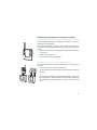
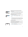
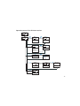
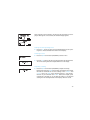
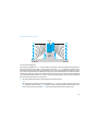
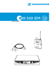
Mikroport® System 2015
Bedienungsanleitung
Instructions for use
Notice d’emploi
Istruzioni per l’uso
Instrucciones de uso
Gebruiksaanwijzing
1
Bedienungsanleitung........................................................................................3
Instructions for use ........................................................................................ 55
Notice d’emploi .............................................................................................105
Istruzioni per l’uso........................................................................................157
Instrucciones de uso ....................................................................................209
Gebruiksaanwijzing .....................................................................................261
Sennheiser, Mikroport und Soundfield sind eingetragene Warenzeichen
der Sennheiser electronic GmbH & Co. KG, Wedemark
Sennheiser, Mikroport and Soundfield are registrated trademarks of
Sennheiser electronic GmbH & Co. KG, Wedemark, Germany
Sennheiser, Mikroport et Soundfield sont des marques déposées de
Sennheiser electronic GmbH & Co. KG, Wedemark, Allemagne
Sennheiser, Mikroport e Soundfield sono marchi commerciali registrati della
società Sennheiser electronic GmbH & Co. KG, Wedemark, Germania
Sennheiser, Mikroport y Soundfield son marcas registradas de la sociedad
Sennheiser electronic GmbH & Co. KG, Wedemark, Alemania
Sennheiser, Mikroport en Soundfield zijn geregistreerde merknamen van
Sennheiser electronic GmbH & Co. KG, Wedemark, Duitsland
2
Mikroport® System 2015
Instructions for use
55
Safety instructions
Never open an electronic unit! If units are opened by customers in breach of
this instruction, the warranty becomes null and void.
Keep the units away from central heating radiators and electric heaters.
Never expose them to direct sunlight.
Use the units in dry rooms only.
Use a damp cloth for cleaning the units. Do not use any cleansing agents or
solvents.
Thank you for choosing Sennheiser!
We have designed these products to give you reliable operation over many
years. Over half a century of expertise in the design and manufacture of
high-quality electro-acoustic equipment have made Sennheiser a worldleading company in this field.
Please take a few moments to read these instructions carefully, as we want
you to enjoy your new Sennheiser products quickly and to the fullest.
56
Contents
Information for users of
the receiver
Information for users of
the transmitter
Information for the
technical expert
Safety instructions ......................................................................56
The 2015 Mikroport® System ...................................................59
The operating principle of the 2015 Mikroport® System ................ 59
Delivery includes ..........................................................................60
Operating controls of the EK 2015 receiver ...........................61
Indications and displays on the receiver ............................................. 62
Operating controls of the SK 2015 transmitter ....................64
Indications and displays on the transmitter ...................................... 65
Preparing the units for use ........................................................67
Transporting the transmitter and receiver ......................................... 67
Inserting the battery pack/batteries (transmitter and receiver) .. 67
Connecting sound sources to the transmitter ................................... 68
Connecting the receiver to hearing aids or headphones ................. 70
Attaching the transmitter or receiver to clothing ............................. 71
Using the receiver ........................................................................72
Switching the receiver on/off ................................................................ 72
Activating/deactivating the lock mode .............................................. 72
Adjusting the level of the received audio signal ............................... 73
Adjusting the level of the internal microphone ................................. 73
Switching the channel ............................................................................. 73
Displaying the frequency ....................................................................... 74
Operating menu of the EK 2015 receiver ............................................ 75
Using the transmitter .................................................................76
Switching the transmitter on/off ......................................................... 76
Muting the microphone .......................................................................... 76
Activating/deactivating the lock mode .............................................. 77
Displaying the frequency ....................................................................... 77
Working with the transmitter’s operating menu .............................. 78
Overview of menus .................................................................................. 80
Operating menu of the SK 2015 transmitter ..................................... 81
Adjustment tips for the operating menu of the transmitter .......... 82
57
Troubleshooting ...........................................................................84
Error checklist .......................................................................84
Recommendations and tips ................................................................... 85
Care and maintenance ................................................................86
Configuration of the units by the technical expert ..............87
Working with the configuration menu ................................................ 87
Overview of menus .................................................................................. 89
Structure of the configuration menu of the EK 2015 receiver ....... 90
Structure of the configuration menu of the SK 2015 transmitter 92
Adjustment tips for the configuration menu ..................................... 93
Colored battery doors and face plates ................................................ 97
Additional information ........................................................................... 98
Specifications ............................................................................ 100
Connector assignment ..........................................................................102
System variants and accessories ........................................... 103
Warranty regulations ............................................................... 313
Declaration of conformity............................................... 316, 317
58
The 2015 Mikroport® System
The 2015 Mikroport® System allows the integration of people with hearing problems in schools and universities, at the workplace and in their free time. Design and characteristics of the 2015 Mikroport® System
are ideally suited to the needs of the users. Operation is simple and easy to learn. The units are small, lightweight and unobtrusive when worn.
The operating principle of the 2015 Mikroport® System
The speaker, for example the teacher, wears the SK 2015 transmitter. The person with hearing problems,
the pupil in this case, wears the EK 2015 receiver. The receiver can be equipped either with a connecting
cable for a hearing aid or with headphones. Without wires and with full freedom of movement, the pupil
can now hear the teacher as if he were sitting right next to him. For the time in which the teacher is speaking, ambient noise is reduced markedly, so that the dialog between teacher and pupil has priority at all
times. When the teacher is not speaking, the pupil can hear his fellow pupils either via the microphones in
the hearing aid or via the internal microphone in the receiver. The 2015 Mikroport® System gives reliable
assistance, even in difficult listening situations. The transmitting power is sufficient for relatively large distances. The MKE 2015-2 clip-on microphone ensures a high degree of intelligibility as well as the possibility
to lip-read at the same time. The highest degree of intelligibility is ensured by the ME 2015-H headset
microphone (optional accessory). Due to the position close to the mouth, loud background noise and bad
acoustics are faded out. The wide range of accessories allows the receiver to be connected to almost any
hearing aid; it can be coupled to the latter either electrically or inductively.
Transmitter and receiver are powered via the BA 2015 battery pack. The operating time of the battery pack
is sufficient for a normal working day (up to 12 hours). The charging contacts on transmitter and receiver
allow the units to be charged in the L 2015 charger without the necessity of removing the battery pack.
If power supply is not available for recharging the battery pack, you can alternatively use 1.5 V AA size batteries. When powered by batteries, transmitter and receiver can also be used for up to 12 hours.
Additional audio sources (e.g. CD player, television, sound card of a computer) can be connected to the
3.5 mm jack socket of the transmitter.
Especially for integrative schools, there is the advantage that you can combine the 2015 Mikroport® System with the Soundfield EMP 2015 System. In addition, transmitters and receivers of the evolution wireless
series can be used together with the 2015 Mikroport® System. For details, please visit our web site at
www.sennheiserusa.com.
59
Delivery includes
MKE 2015-2
SK 2015
MZQ 2
BA 2015
EK 2015
L 2015
y
y
y
y
y
y
y
y
1 SK 2015 transmitter
1 MKE 2015-2 clip-on microphone
1 EK 2015 receiver
2 BA 2015 battery pack
1 L 2015 charger
1 MZQ 2 microphone clip
1 power supply NT 1
1 EZB 2015 system case
incl. transport case, transport holding device (for EK 2015 and
SK 2015) and shoulder strap
y 2 EZG 2015 pouches with one neck strap each
y 3 instructions for use:
Instructions for use of 2015 Mikroport® System
Instructions for use of MKE 2015-2
Instructions for use of L 2015
Note:
All components of the 2015 Mikroport® System are also available separately (see “System variants and accessories“ on page 103).
EZB 2015
transport case
transport holding
device
EZG 2015
60
The 2015 Mikroport® System consists of the following components:
Operating controls of the EK 2015 receiver
Operating controls
LC display panel
Headphone output (HI), 3.5 mm jack socket
Output for hearing aids (LOW), 2.5 mm jack
Alphanumeric display
5-step level display for received audio signal
socket
Antenna
Red LED for battery status and missing trans
mitter RF signal indication
Green LED for audio signal indication
Charging contacts
SET button
/ rocker button (UP/DOWN)
Battery compartment
Battery compartment cover
Unlocking button
ON/OFF button with ESC function
Internal microphone
LC display
(FM)
5-step display for microphone level (MIC)
of internal microphone (only with switched-on
internal microphone)
Lock mode icon (lock mode is activated)
4-step battery status display
5-step level display for received RF signal
Note:
Depending on the individual configuration of
your receiver, some of the displays shown here
may not appear on the display panel.
61
Indications and displays on the receiver
Battery status indication
The 4-step battery status display on the display panel and the red LED provide information on the capacity of the BA 2015 battery pack or the batteries:
3 segments:
capacity approx. 100 %
2 segments:
capacity approx. 70 %
1 segment:
capacity approx. 30 %
Battery status display
and red LED flashing:
LOW BAT (you should immediately
replace the battery pack or the batteries)
Warning indication for missing RF signal
The red LED lights up constantly when no RF signal is being received, e.g.
because the microphone of the transmitter is muted.
Audio signal indication
The green LED lights up when an audio signal of sufficient strength (e.g.
the voice of the speaker) is being received.
Alphanumeric display
62
After switching on the receiver, the alphanumeric display first displays
the name of the receiver. After approx. three seconds, the standard display
appears, indicating the channel bank (1) and the channel (01).
Display for the audio level
The display shows the level of the received audio signal.
Display for microphone level (internal microphone)
The display shows the level of the internal microphone.
Note:
Depending on the configuration of your receiver, this display may not
appear on the display panel.
Display for the RF level
The display shows the level of the received RF signal. The more segments
displayed, the better the reception.
Display for lock mode
If the lock mode is activated, the lock mode icon appears on the standard
display. If the lock mode is deactivated, the lock mode icon disappears from
the standard display.
Display backlighting
After pressing a button, the display remains backlit for approx. 15 seconds.
63
Operating controls of the SK 2015 transmitter
Operating controls
64
Audio input (LINE), 3.5 mm jack socket
Microphone input (MIC), 2.5 mm jack socket
Antenna
Red LED for battery status and muting
indication
Yellow LED for audio peak
Charging contacts
SET button
/ rocker button (UP/DOWN)
Battery compartment
Battery compartment cover
Unlocking button
ON/OFF button with ESC function
LC display
MUTE switch for microphone input
LC display panel
Alphanumeric display
5-step display for line level (LINE)
5-step display for microphone level (MIC)
Lock mode icon (lock mode is activated)
4-step battery status display
Note:
Depending on the individual configuration of
your transmitter, some of the displays shown
here may not appear on the display panel.
Indications and displays on the transmitter
Battery status indication
The 4-step battery status display on the display panel and the red LED provide information on the capacity of the BA 2015 battery pack or the batteries:
3 segments:
capacity approx. 100 %
2 segments:
capacity approx. 70 %
1 segment:
capacity approx. 30 %
Battery status display
and red LED flashing:
LOW BAT (you should immediately replace
the battery pack or the batteries)
MUTE indication
The red LED lights up constantly when the microphone of the transmitter
is muted.
Audio peak indication
The yellow LED should only light up briefly during peak level passages.
When it lights up constantly, the line or microphone input level is too high.
Alphanumeric display
After switching on the transmitter, the alphanumeric display first displays the name of the transmitter. After approx. three seconds, the standard display appears, indicating the channel bank (1) and the channel (01).
65
Display for line level
The display for line level (LINE) shows the level of the line input. The display should show full deflection only during the loudest passages.
Display for microphone level
The display for microphone level (MIC) shows the level of the connected
microphone. The display should show full deflection only when you speak
very loudly.
Display for lock mode
If the lock mode is activated, the lock mode icon appears on the standard
display. If the lock mode is deactivated, the lock mode icon disappears from
the standard display.
Display backlighting
After pressing a button, the display remains backlit for approx. 15 seconds.
66
Preparing the units for use
Transmitter and receiver have been adapted by your technical expert to suit
your individual applications.
Transporting the transmitter and receiver
In addition to the EZB 2015 system case offering room to store all components of the system, delivery also includes a transport case. This is suitable
for the day-to-day transport of a transmitter and a receiver and of two
replacement battery packs.
Transport
case
Push the transmitter and the receiver into the transport holding device as
shown on the left. The units fit snugly in the case preventing damage during transport. It is possible to store the battery packs in the front pocket of
the transport case, as well as in the transport holding device.
Transport holding
device
Inserting the battery pack/batteries
(transmitter and receiver)
For powering the units, we recommend using the supplied BA 2015 battery
pack. The battery pack can be recharged in the L 2015 charger while
remaining in the transmitter or receiver (see operating manual of the
charger). If no power supply is available for recharging the battery pack,
you can alternatively use 1.5 V AA size batteries.
Press the two unlocking buttons and open the battery compartment
cover .
Insert the battery pack or the batteries as shown on the left. Please
observe correct polarity when inserting the battery pack or the batteries.
Close the battery compartment. The battery compartment cover locks
into place with an audible click.
67
How to properly use the battery pack or the batteries
For battery pack operation, only use the BA 2015 battery pack in order to
ensure optimum operational reliability. Batteries and rechargeable battery
cells have different discharging curves. Transmitter and receiver are able to
identify the BA 2015 battery pack and to use it to full capacity. They also
adapt the battery status display according to the type of power supply used
(batteries or battery pack). Individual rechargeable battery cells will not be
identified as battery packs.
After use (e.g. during the night), charge the BA 2015 battery pack of
the transmitter or receiver in the L 2015 charger. The maximum charging time is 2.5 hours, at which time the unit then switches to trickle
charging.
If you do not use the transmitter or receiver for extended periods of
time (e.g. while you are on holiday), remove the battery pack or the
batteries. After three months at the latest, the battery packs will need
a refresh charge in the L 2015 charger. This prevents damage to the
battery pack due to self-discharge.
Connecting sound sources to the transmitter
Connecting the microphones to the transmitter
In addition to the supplied MKE 2015-2 clip-on microphone, a plug-on
microphone (MKE 2015-0) and a headset microphone (ME 2015-H) are
available as optional accessories. DC powering of these condenser microphones is via the microphone input.
Connect the 2.5 mm jack plug of the microphone or the microphone
cable to the transmitter’s 2.5 mm jack socket (MIC) .
Via the operating menu, adjust the sensitivity of the microphone input
(see “Adjusting the microphone sensitivity“ on page 82).
68
Attaching and positioning the microphones
The MKE 2015-2 clip-on microphone (supplied) and the MKE 2015-0 plugon microphone (optional accessory) are omni-directional and pick up sound
equally from all directions. They are the best choice if movements of the
speaker’s head have to be compensated for. However, they should be
attached as close as possible to the sound source.
Use the microphone clip to attach the MKE 2015-2 clip-on microphone to
MKE 2015-2 clothing (e.g. tie, lapel) at a maximum distance of 9.8 inches from your
mouth.
MKE 2015-0
When using the MKE 2015-0 plug-on microphone, wear the transmitter
around your neck using the EZG 2015 pouch with neck strap. Adjust the
length of the neck strap so that the distance between the microphone and
your mouth is 9.8 inches at the most.
You can use the MKE 2015-0 plug-on microphone to transmit the speech of
several persons at a time with only one transmitter. Put the transmitter
with the plug-on microphone on the table in front of the speaker. The person speaking should keep a distance of approx. 9.8 inches to the microphone.
The ME 2015-H headset microphone (optional accessory) has a super-cardioid pick-up pattern.
Adjust the ME 2015-H headset microphone so that a comfortable and
secure fit is ensured.
ME 2015-H
Position the microphone of the headset at the corner of your mouth.
Make sure that the sound inlet is directed towards your mouth. The
sound inlet is marked with a little dot.
69
Connecting audio sources to the transmitter
You can connect audio sources such as a CD player, a television, or the sound
card of a computer to the line input of the transmitter.
Connect the 3.5 mm jack plug of the connecting cable to the transmitter’s 3.5 mm jack socket (LINE) .
Via the operating menu, adjust the sensitivity of the line input (see
“Adjusting the sensitivity of the line input“ on page 82).
Note:
If the transmitter is preset so that the line input is switched off, the display for line level is not shown on the display panel.
Connecting the receiver to hearing aids or headphones
Connecting the receiver to hearing aids with direct audio input
Connect a hearing aid with direct audio input to the receiver’s 2.5 mm
jack socket (LOW) . Suitable connecting cables (see “System variants
and accessories“ on page 103) are available from your Sennheiser dealer.
Connecting the receiver to a hearing aid without audio input
(hearing aid must have Telecoil)
Connect the EZT 2015 induction neck loop or the EZI 120 induction
couplers for hearing aids without audio input to the receiver’s 3.5 mm
jack socket (HI) . Suitable connecting cables for the induction couplers (see “System variants and accessories“ on page 103) are available
from your Sennheiser dealer.
Connecting the headphones
You must only connect headphones with a stereo jack plug and a minimum
impedance of 32 Ω to the receiver (see “Connector assignment“ on
page 102).
Connect the headphones to the receiver’s 3.5 mm jack socket (HI).
70
Attaching the transmitter or receiver to clothing
Attaching the transmitter or receiver to clothing using the belt clip
Using the supplied belt clip, you can attach the transmitter or receiver to
clothing (e.g. belt, waistband).
The belt clip is detachable so that you can also attach the transmitter or
receiver with the antenna pointing downwards. To do so, attach the clip as
follows:
Remove the belt clip from its fixing points by pushing in the direction
of the arrows.
Rotate the belt clip by 180°.
Insert the belt clip into its fixing points.
Wearing the transmitter or receiver around your neck
Using the EZG 2015 pouch, you can wear the transmitter or receiver around
your neck.
Insert the transmitter or receiver into the pouch.
Use the snap hooks to attach the neck strap to the eyelet of the pouch
as shown.
Note:
When using the transmitter with the MKE 2015-0 plug-on microphone
(optional accessory), adjust the length of the neck strap so that the distance between the microphone and your mouth is 9.8 inches at the
most.
71
Using the receiver
After you have switched on the receiver, it can then be operated with the
SET button and the / rocker button (UP/DOWN) , making it very
easy to use for children. All settings become effective immediately. The display then switches back to the standard display.
Switching the receiver on/off
Press the ON/OFF button to switch the receiver on. The name of the
receiver is displayed for approx. three seconds and then switches to the
standard display.
To switch the receiver off, press the ON/OFF button until “OFF”
appears on the display.
Activating/deactivating the lock mode
The receiver has a lock mode that prevents accidental programming or
switching off during operation.
Press the SET button and keep it pressed.
Press the button (DOWN) . “LOCK” appears on the display. The lock
mode is activated and the lock mode icon appears on the standard
display.
To deactivate the lock mode, press the SET button again and keep it
pressed.
72
Press the button (DOWN) . “UNLOCK” appears on the display. The
lock mode is deactivated and the lock mode icon disappears from the
standard display.
Adjusting the level of the received audio signal
You can adjust the level of the received audio signal (e.g. the voice of the
speaker) in 64 steps.
Use the / rocker button (UP/DOWN) to adjust the level of the
received audio signal so that you can hear the speaker loud and clear.
Adjusting the level of the internal microphone
You can adjust the level of the internal microphone (via which you can hear
environmental sounds) in 64 steps.
Press the SET button . The current level is displayed.
Use the / rocker button (UP/DOWN) to adjust a comfortable
level.
Note:
You can only adjust the level of the internal microphone when the internal microphone is switched on in the receiver’s configuration. If, in addition, the automatic priority circuit is switched on, the internal
microphone is faded out as soon as speech is being transmitted.
Switching the channel
You can only switch between the released channels. This can be necessary
when the selected channel is subject to interference.
Always set the receiver to the same channel as the transmitter. If interference occurs, check to ensure that the same frequency is assigned to the
same channel on both transmitter and receiver.
Press the SET button and keep it pressed for approx. five seconds.
The current channel is displayed.
Use the / rocker button (UP/DOWN) to select a channel.
73
Displaying the frequency
You can display the frequency stored in the selected channel. If you operate
your system on one of the channels with a freely selectable frequency
(channel bank “U”), this feature is very important as it allows you to check
if the transmitter and the receiver are set to the same frequency.
74
Press the SET button and keep it pressed.
Press the button (UP) . The current frequency is displayed.
Operating menu of the EK 2015 receiver
after 3 seconds
FM. 17
FM. 28
Current setting
/ : 01...64
after 3 seconds
SET
MIC. 28
MIC. 38
/ : 01...64
Current level of
internal
microphone (only
if microphone is
switched on)
after 3 seconds
Press SET
1.01
8.16
for 5 seconds Current channel
/ : all released
channels
after 7 seconds U.01...U.20,
1.01...8.20
SET + SET + LOCK
UNLOCK
after
2 seconds
Activating the
lock mode
Lock mode
activated
Lock mode
deactivated
after 2 seconds
SET + after
2 seconds
749.800
Current
frequency
75
Using the transmitter
Switching the transmitter on/off
Press the ON/OFF button to switch the transmitter on. The name of
the transmitter is displayed for approx. three seconds and then
switches to the standard display.
To switch the transmitter off, press the ON/OFF button until “OFF”
appears on the display.
Note:
The transmitter can only be switched off when the standard display is
shown on the display panel. When in the operating menu, briefly pressing the ON/OFF button will cancel your entry (ESC function) and return
you to the standard display with the last stored settings.
Muting the microphone
The transmitter has a MUTE switch that noiselessly mutes the transmitted microphone signal. This switch does not switch off the transmitter.
Set the MUTE switch to the position “MUTE”. The red LED lights up.
Set the MUTE switch back to the original position to activate the microphone signal.
76
Activating/deactivating the lock mode
The transmitter has a lock mode that prevents accidental programming or
switching the power off during operation. However, you can still mute the
microphone.
Press the SET button .
Press the button (DOWN) . “LOCK” appears on the display. The lock
mode is activated and the lock mode icon appears on the standard
display.
To deactivate the lock mode, press the SET button again and keep it
pressed.
Press the button (DOWN) . “UNLOCK” appears on the display. The
lock mode is deactivated and the lock mode icon disappears from the
standard display.
Displaying the frequency
You can display the frequency stored in the selected channel. If you operate
your system on one of the channels with a freely selectable frequency
(channel bank “U”), this feature is very important as it allows you to check
if transmitter and receiver are set to the same frequency.
Press the SET button and keep it pressed.
Press the button (UP) . The current frequency is displayed.
77
Working with the transmitter’s operating menu
By way of example of the “CHAN” menu, this section describes how to use
the transmitter’s operating menu.
Function of the buttons
Mode
Buttons To ...
Standard display ON/OFF
Operating menu
Setting mode
78
switch the transmitter on/off
SET
get into the operating menu
/
without function
ON/OFF
cancel the entry and return to the
standard display
SET
get into the setting mode of the
selected menu
/
change to the previous menu () or
change to the next menu ()
ON/OFF
cancel the entry and return to the
standard display
SET
store the settings and return to the
previous menu level
/
adjust the setting of the selected menu:
option (/)
After switching on the transmitter, the name of the transmitter is first displayed. After approx. three seconds, the standard display appears.
Getting into the operating menu
Press the SET button to get from the standard display into the operating menu. The last selected menu flashes on the display.
Selecting a menu
Press the / rocker button (UP/DOWN) to select a menu.
Press the SET button to get into the setting mode of the selected menu.
The current setting that can be adjusted flashes on the display.
Adjusting a setting
Press the / rocker button (UP/DOWN) to adjust the setting.
By briefly pressing the / rocker button, the display jumps either
forwards or backwards to the next setting. In the “SENSIT” and
“CHAN” menu, the / rocker button features a “fast search”
function: If you hold down the or button, the display cycles
continuously, allowing you to get fast and easily to your desired
setting. The new setting flashes on the display until it is stored.
79
Storing a setting
Press the SET button to store the setting. “STORED” appears on the display, indicating that the setting has been stored. The display then
returns to the top menu level.
With most menus, new settings become effective immediately
without having to be stored. An exception is the “CHAN” menu.
With this menu, new settings only become effective after they have
been stored (“STORED” appears on the display, indicating that the
setting has been stored).
Exiting the operating menu
Select the “EXIT” menu to exit the operating menu and to return to the
standard display.
When in the operating menu, briefly pressing the ON/OFF button
will cancel your entry (ESC function) and return you to the standard
display without storing the setting.
Overview of menus
80
Display
Function of the menu
SENSIT (MIC)
Adjusting the sensitivity of the microphone
input
SENSIT (LINE)
Adjusting the sensitivity of the line input
CHAN
Switching the channel
EXIT
Exiting the operating menu and returning to
the standard display
Operating menu of the SK 2015 transmitter
ON/OFF
Cancels your entry
on all levels of the
operating menu
EXIT
after 3 seconds
1.17
SET
SENSIT
SET
Adjusting the
microphone
sensitivity
SEN. 32
SEN. 12
Current sensitivity
setting
/ : 1...32 dB
SET: Stores the
setting
SET
STORED
SENSIT
SET
Adjusting the line
input sensitivity
SEN. OFF
SEN. 18
Current sensitivity
setting
/ : OFF, 1...32 dB
SET: Stores the
setting
SET
STORED
CHAN
Selecting a
channel
SET
SET
1.17
5.20
Current channel (only released
channels can be selected)
/ : U.01...20,
1.01...8.20
SET: Stores the
setting
STORED
SET
EXIT
Exiting the
operating menu
SENSIT
SET + LOCK
Activating the
lock mode
after
2 seconds
SET + Lock mode
activated
UNLOCK
Lock mode
deactivated
after 2 seconds
SET + after 2 seconds
749.800
Current
frequency
81
Adjustment tips for the operating menu of the
transmitter
Adjusting the microphone sensitivity
SENSIT (MIC)
Via the “SENSIT (MIC)” menu, you can adjust the sensitivity of the connected microphone in 32 steps. The microphone sensitivity is correct
adjusted when the display for microphone level (MIC) shows full deflection only when you speak very loudly. The yellow LED should only light
up briefly.
Note:
For monitoring the adjusted microphone sensitivity, the display for
microphone level (MIC) is always indicated – even when the microphone is muted.
Adjusting the sensitivity of the line input
SENSIT (LINE)
Via the “SENSIT (LINE)” menu, you can adjust the sensitivity of the line
input in 32 steps.
The input sensitivity is adjusted too high when loud passages cause overmodulation in the transmission link. In this case, the yellow LED will light
up for longer periods of time. If, on the other hand, the sensitivity is
adjusted too low, the transmission link will be undermodulated, which
would result in a signal with high background noise.
The sensitivity is correctly adjusted when the display for line level (LINE) shows full deflection only during the loudest passages.
Note:
If the sensitivity of the line input is set to “OFF”, the display for line level
(LINE) is not shown on the display panel.
82
Switching between the channels
CHAN
Via the “CHAN” menu, you can switch between the released channels. This
can be necessary when the selected channel is subject to interference.
With the 2015 System, a transmitter can be received by several receivers
on the same frequency. In this case, it may be necessary to switch to a channel that is released on all receivers.
Always set the transmitter and the receiver(s) of a transmission link to the
same channel. For multi-channel operation, only use the released channels
in one channel bank and, if possible, only use the channel banks “1” to “8”
since these accommodate fixed preset frequencies which are intermodulation-free.
Exiting the operating menu
EXIT
Via the “EXIT” menu, you can exit the operating menu and return to the
standard display.
83
Troubleshooting
Error checklist
Problem
Possible cause
Possible solution
No display on the
display panel
Battery pack or batteries at low
capacity.
Recharge the battery pack or
replace the batteries.
Receiver: No RF signal Transmitter and receiver are not
on the same channel/frequency.
The transmitter is out of range.
Set transmitter and receiver to the same
channel. Check if the frequency is the
same. If this is not the case, set
transmitter and receiver to a different
channel.
Reduce the distance between
transmitter and receiver.
The technical expert must check the
squelch threshold setting.
Receiver: RF signal
available,
but no audio signal
The transmitter’s microphone is
muted (“MUTE”).
Deactivate the muting function.
Microphone signal has The transmitter’s microphone
sensitivity is adjusted too low.
a high level of
background noise
Via the “SENSIT (MIC)” menu, increase
the microphone sensitivity.
Line signal has a high The transmitter’s line sensitivity is
adjusted too low.
level of background
noise
The transmitter’s microphone signal
interferes with the line signal.
Via the “SENSIT (LINE)” menu, increase
the line sensitivity.
Microphone signal is
distorted
Via the “SENSIT (MIC)” menu, reduce the
microphone sensitivity.
The transmitter’s microphone
sensitivity is adjusted too high.
Mute the transmitter’s microphone
(“MUTE”).
Line signal is distorted The transmitter’s line sensitivity is Via the “SENSIT (LINE)” menu, reduce
adjusted too high.
the line sensitivity.
84
Problem
Possible cause
Possible solution
No access to a certain The channel has not been released. Set transmitter and receiver to a
channel
different channel.
The technical expert must release the
channel.
If problems occur that are not listed in the above table or if the problems cannot be solved with the proposed solutions, please contact your technical expert for assistance.
Recommendations and tips
... for system planning
y Transmitter and receiver of a transmission link must be set to the same frequency.
y A transmitter can be received by several receivers on the same frequency.
y However, a receiver cannot receive several transmitters on the same frequency. Incorrect settings are
indicated by crackling and chirping in the receiver.
... for the MKE 2015-0 plug-on microphone (optional accessory)
y Adjust the length of the neck strap so that the distance between the microphone and your mouth is
9.8 inches at the most.
y The plug-on microphone allows you to transmit group discussions. For this purpose, place the transmitter on the table on a soft and springy pad.
... for the ME 2015-H headset microphone (optional accessory)
y Always use the microphone with a popshield and position the microphone at the corner of the mouth.
y You can vary the bass reproduction by increasing/decreasing the talking distance.
y Make sure that the sound inlet is directed towards the mouth. The sound inlet is marked with a little
dot.
... for the SK 2015 transmitter
y Make sure that the antenna and the microphone cable do not cross.
y For best results, make sure that the transmitter sensitivity is correctly adjusted.
85
... for optimum reception
y The system’s range depends to a large extent on location and can be up to 164 feet. There should be
a “free line of sight” between transmitting and receiving antenna.
... for multi-channel operation
y For multi-channel operation, you can only use the channels in a channel bank. Each of the channel
banks “1” to “8” accommodates factory-preset frequencies which are intermodulation-free. For alternative frequency combinations, please refer to the enclosed frequency table. The freely selectable frequencies can be selected via the “TUNE” menu and can be stored in the channel bank “U”.
y When using several transmitters simultaneously, interference can be avoided by maintaining a minimum distance of 7.8 inches between two transmitters.
y For multi-channel applications, use special accessories (see “System variants and accessories“ on
page 103).
Care and maintenance
y Use a slightly damp cloth to clean the units from time to time.
Note:
Do not use any cleansing agents or solvents.
y If you do not use the transmitter or receiver for extended periods of time (e.g. while you are on holiday), remove the battery pack or the batteries. After three month, the battery packs will need a refresh
charge in the L 2015 charger. This prevents damage to the battery pack due to self-discharge.
86
Configuration of the units by the technical
expert
Depending on the area of application, the technical expert configures the
transmitter and the receiver for optimum use.
Working with the configuration menu
By way of example of the “FADE” menu, this section describes how to use
the configuration menu.
Function of the buttons
Mode
Buttons
“SETUP” display ON/OFF
Configuration
menu
Setting mode
To ...
switch the transmitter or receiver on/off
SET
get into the configuration menu
/
without function
ON/OFF
cancel the entry and return to the
“SETUP” display
SET
get into the setting mode of the selected
menu
/
change to the previous menu () or
change to the next menu ()
ON/OFF
cancel the entry and return to the
“SETUP” display
SET
store the settings and return to the
configuration menu
/
adjust the setting of the selected menu:
option (/)
87
Getting into the configuration menu
Note:
In order to get into the configuration menu, the transmitter or receiver
must be switched off.
Press the SET button and keep it pressed.
Press the ON/OFF button and keep it pressed for approx. five
seconds. “SETUP” appears on the display.
Press the SET button to get into the configuration menu.
Selecting a menu
Press the / rocker button (UP/DOWN) to select a menu.
Press the SET button to get into the setting mode of the selected menu.
The current setting that can be adjusted flashes on the display.
Adjusting a setting
Press the / rocker button (UP/DOWN) to adjust the setting.
By briefly pressing the / rocker button, the display jumps either
forwards or backwards to the next setting. In the “FADE”, “TUNE“,
“NAME“ and “ACCESS” menu, the / rocker button features a
“fast search” function: If you hold down the or button, the
display cycles continuously, allowing you to get fast and easily to
your desired setting. The new setting flashes on the display until it
is stored.
88
Storing a setting
Press the SET button to store the setting. “STORED” appears on the display, indicating that the setting has been stored. The display then
returns to the top menu level.
With most menus, new settings become effective immediately
without having to be stored. An exception are the “RESET” menus
of both transmitter and receiver and the “TUNE” menu of the transmitter. With these menus, new settings only become effective after
they have been stored.
Exiting the configuration menu
When in the configuration menu, briefly pressing the ON/OFF button will
cancel your entry (ESC function) and return you to the “SETUP” display
without storing the setting.
Overview of menus
Display
SETUP
INT.MIC
FADE
SQELCH
ACCESS
TUNE
NAME
RESET
Receiver
Standard display in the configuration
menu
Switching the internal microphone
on/off
Adjusting the gain reduction of the
automatic priority circuit
Adjusting the squelch threshold
Releasing channels for the user
Setting a frequency for a selected
channel in the channel bank “U” (user
bank)
Entering a name
Resetting the unit to the factorypreset default settings
Transmitter
Standard display in the configuration
menu
–
–
–
Releasing channels for the user
Setting a frequency for a selected
channel in the channel bank “U” (user
bank)
Entering a name
Resetting the unit to the factorypreset default settings
89
Structure of the configuration menu of the EK 2015 receiver
Transmitter must be switched off.
Simultaneously press SET and ON/OFF and keep both buttons pressed for 5 seconds
RESET
SETUP
SET
INT.MIC
SET
Switching the
internal
microphone on or
off
MIC. OFF
MIC. ON
Internal
microphone
switched on or
off
/ : ON/OFF
ON/OFF
Cancels your entry
on all levels of the
operating menu
SET: Stores the
setting
SET
STORED
FADE
SET
Adjusting the gain
reduction of the
automatic priority
circuit
FAD. OFF
FAD. 29
Current gain
reduction setting
/ : OFF, 01...64
STORED
SQELCH
SET
Adjusting the
squelch
threshold
Releasing
channels for the
user
SET
SQ LO
SQ MID
/ : LO, MID,HI
Displays
channels that
can be released
STORED
90
SET: Stores the
setting
SET
SET
1.01
Press SET for 1 second
The selected channels
are released
TUNE
SET
Current squelch
threshold
STORED
ACCESS
SET: Stores the
setting
5.20
ACCESS
/ : U.01...20,
1.01...8.20,
ERASE
Channel
released:
"ACCESS" is
displayed briefly
The next channel
that can be
released is
displayed
ON/OFF
Cancels your entry
on all levels of the
operating menu
ACCESS
SET
SET
TUNE
U.01
U.04
Setting a
frequency for a
selected channel
in the channel
bank "U"
Current channel
Select a channel
U.01...U.20
744.500
Current
frequency of
the selected
channel
744.650
/ : Receiving
SET
STORED
NAME
SET
Assigning a name
EK 2015
PETE15
Current name
/ : Enter a name (6 characters)
STORED
RESET
Loading the
factory-preset
default settings
SET
frequency
tunable in steps
of 25 kHz
SET: Stores the
setting
SET
Letters w/o pronounciation marks,
numbers from 0...9, special
characters, spaces
SET: 5 x next character, then store
the setting
RST. NO
RST. OK
Confirm your
selection
/ :
SET
/ :
OK
SET: Unit loads factory-preset
default settings, unit is restarted,
"SETUP" display appears
NO
SET: Reset is cancelled
SET
INT.MIC
SETUP
91
Structure of the configuration menu of the SK 2015 transmitter
Transmitter must be switched off.
Simultaneously press SET+ON/OFF and keep both buttons pressed for 5 seconds
RESET
SETUP
ACCESS
SET
SET Releasing
channels for the
user
ON/OFF
Cancels your entry
on all levels of the
operating menu
SET
1.01
5.20
Displays
channels that
can be released
ACCESS
/ : U.01...20,
Channel released:
"ACCESS" is
displayed briefly
1.01...8.20,
ERASE
Press SET
for 1
The selected channels are released
The next channel that
can be released is
displayed
STORED
SET
SET
TUNE
U.01
U.04
744.500
744.650
Setting a
frequency for a
selected channel
in the channel
bank "U"
Current channel
/ : U.01...20
Current
frequency of the
selected
channel
/ : Transmittion
frequency tunable
in steps of 25 kHz
SET: Stores the
setting
SET
STORED
NAME
SET
Assigning a
name
SK 2015
PETE15
Current name
/ : Enter a name (6 characters)
STORED
RESET
Loading the
factory-preset
default settings
SET
RST. NO
RST. OK
Confirmation
/ :
SET
ACCESS
92
SET
Letters w/o pronounciation marks,
numbers from 0...9, special
characters, spaces
SET: 5 x next character, then store
the setting
OK
SET: Unit loads factory-preset
default settings, unit is restarted,
"SETUP" display appears
/ :
NO
SET: Reset is cancelled
SET
SETUP
Adjustment tips for the configuration menu
Switching the internal microphone on or off (receiver only)
INT.MIC
The EK 2015 receiver has an internal microphone that picks up environmental sounds. The internal microphone can be switched on or off on via the
“INT.MIC” menu.
Adjusting the gain reduction of the automatic priority circuit
(receiver only)
FADE
The receiver is equipped with an automatic priority circuit. This ensures that
the gain of the hearing aid microphones or of the receiver’s internal microphone is reduced during speech transmission. The speaker has automatic
priority over environmental sounds, providing for better speech intelligibility with the receiver. The internal microphone in the receiver has a preset
gain reduction. For the hearing aid microphones, in contrast, you can adjust
the gain reduction via the “FADE” menu. The higher the set value, the
greater the gain reduction. In the “OFF” setting, the automatic priority circuit is switched off, i.e. the gain of the microphones is not reduced while the
speaker is talking.
A speech filter completes the automatic priority circuit, ensuring that interfering noise such as banging doors do not trigger the automatic priority circuit.
Adjusting the squelch threshold (receiver only)
SQELCH
The receiver is equipped with a squelch that can be adjusted via the
“SQELCH” menu. The squelch eliminates annoying noise when the transmitter is switched off. It also suppresses sudden noise when there is no
longer sufficient transmitter power received by the receiver.
There are three possible squelch settings:
y LO =low
y MID =middle
y HI =high
93
Selecting the setting “LO” reduces the squelch threshold, selecting the setting “HI” increases the squelch threshold. Adjust the squelch threshold –
with the transmitter switched off – to the lowest possible setting that suppresses hissing noise.
Important notes:
If the squelch threshold is adjusted too high, the transmission range
will be reduced. Therefore, always adjust the squelch threshold to the
lowest possible setting.
When in the setting mode of the “SQELCH” menu, pressing the
button (DOWN) for more than three seconds will switch off the
squelch. “SQ.OFF” appears on the display. If no RF signal is being received, hissing noise will occur. This setting is for test purposes only.
Releasing channels for the user
ACCESS
Transmitter and receiver have nine channel banks with up to 20 switchable
channels each. Via the “ACCESS” menu, you can restrict access to the channels by only releasing the channels to be available to the user.
Note:
The units are factory-preset so that all channels are available to the
user.
In order to rule out the possibility that channels are released which should
not be available to the user, we recommend that you first lock all channels
and then release individual channels one after the other.
For multi-channel operation, we recommend that you only release the channels in one channel bank. Only use the channel banks “1” to “8” since these
accommodate fixed preset frequencies which are intermodulation-free.
To lock all channels, select “ERASE” from the “ACCESS” menu.
Press the SET button to confirm your selection.
All channels are now locked.
94
To release individual channels, select the desired channel by using the
/ rocker button (UP/DOWN). (By briefly pressing the button, the
display jumps either forwards or backwards to the next channel; by holding down the button, the display cycles continuously.)
Note:
You can display the frequency stored in the selected channel. To do so,
press the SET button and the button (UP) simultaneously.
Briefly press the SET button. The selected channel can now be accessed
by the user. “ACCESS” briefly appears on the display and the display
then displays the next channel that can be released.
Have you released all required channels as described above? Store your
settings by pressing the SET button until “STORED” appears on the display.
Selecting the frequencies to be stored in the channel bank “U”
TUNE
Via the “TUNE” menu, you can select the frequencies to be stored in the
channel bank “U” (user bank). When selecting the “TUNE” menu, the transmitter or receiver automatically switches to the channel bank “U”.
Note:
Always assign the same frequency to the same channel on both transmitter and receiver.
Use the / rocker button (UP/DOWN) to select the channel for which
you want to set the frequency.
Press the SET button to confirm your selection. The currently set frequency is displayed.
Use the / rocker button (UP/DOWN) to select the desired transmission or receiving frequency. The frequencies are tunable in 25-kHz
steps within a switching bandwidth of 36 MHz max. For intermodulation-free frequencies, please refer to the enclosed frequency table.
95
Press the SET button to store your setting.
Entering a name
NAME
Via the “NAME” menu, you can enter a freely selectable name for the transmitter or receiver. This name is briefly shown on the display panel after
switch-on.
The name can consist of up to six characters such as:
y letters (without pronounciation marks),
y numbers from 0 to 9,
y special characters e.g. () - . _ and spaces.
To enter a name, proceed as follows:
After you have entered into the setting mode of the menu, the first segment starts flashing on the display.
Use the / rocker button (UP/DOWN) to select a character. By briefly
pressing the button, the display jumps either forwards or backwards to
the next character. If you hold down the button, the display starts cycling continuously.
Press the SET button to change to the next segment.
After you have entered the name completely press the SET button to
store your setting and to return to the top menu level.
Resetting the unit to the factory-preset default settings
RESET
Via the “RESET” menu, you can reset the unit to the factory-preset default
settings. In order to prevent an accidental reset, a safety query appears on
the display. You can select “NO” or “OK”.
y “NO”: If you select “NO” and confirm your selection by pressing the
SET button, the reset of the unit is cancelled and you return to
the configuration menu.
y “OK”: If you select “OK” and confirm your selection by pressing the
SET button, the unit is reset to the factory-preset default settings. After the reset, the unit is restarted and “SETUP”
appears on the display.
96
Colored battery doors and face plates
For an integrative teaching approach with several children and the teacher
it is important that the children and the teacher distinguish their units easily. Colored battery doors (ordered separately) are available for both the
transmitter and receiver. The receivers face plate can also be replaced with
colored ones (ordered separately). (see “System variants and accessories“
on page 103).
Changing the battery compartment cover
Press the two unlocking buttons and open the battery compartment
cover .
Insert a thin screwdriver into the small recess between the front cover
and the lower part of the housing.
Carefully lever out the front cover on both sides.
First insert the colored front cover into the recess on the upper end of
the battery compartment and then press it down onto the housing.
Close the battery compartment.
Changing the face plate (receiver only)
Press the two unlocking buttons and open the battery compartment
cover .
Use a thin screwdriver to push out the pin of the battery compartment
cover.
Replace the battery compartment cover with a colored one.
Push the pin back in.
Close the battery compartment.
97
Additional information
The channel bank system
The 2015 System is available in three UHF frequency ranges with 1,440 transmission/receiving frequencies
per frequency range. Please note: Frequency usage is different for each country. Your Sennheiser agent will
have all the necessary details on the available legal frequencies for your area.
Range A:
Range B:
Range C:
518 to 554 MHz
626 to 662 MHz
740 to 776 MHz
Transmitter and receiver have nine channel banks with up to 20 switchable channels each.
channel 1
preset frequency
channel 2
preset frequency
channel 20
preset frequency
channel 1
freely selectable frequency
channel 2
freely selectable frequency
channel 20
freely selectable frequency
channel bank 1... 8
channel bank U
Each of the channels in the channel banks “1” to “8” has been factory-preset to a transmission/receiving
frequency (see enclosed frequency table). These frequencies are preset and cannot be changed as countryspecific regulations on frequency usage are taken into account. The channel bank “U” (user bank) allows
you to store your selection out of 1,440 transmission/receiving frequencies that are freely selectable within
the preset frequency range.
An advantage of the factory-preset frequencies is that
y the system is ready for immediate use after switch-on,
y several systems can be operated simultaneously on the preset channels of a channel bank without
causing intermodulation interference.
98
HDX noise reduction system
RF link
Inherent
noise
of the
RF link
Transmitter
Receiver
You can hear the difference:
This product is equipped with HDX, the Sennheiser noise reduction system that reduces RF interference. It
increases the signal-to-noise ratio in wireless audio transmission. HDX is a wideband compander system
which compresses the audio signal in the transmitter in a 2:1 ratio (related to dB) to lift it above the inherent noise floor of the RF link. A 110 dB dynamic range signal is thus transmitted with an effective dynamic
range of only 55 dB, which is above the 60 dB noise floor of the RF link. In the receiver the signal is expanded
in an identical and opposite way in a 1:2 ratio to restore the original signal, at the same time reducing the
RF noise to below the noise floor of the receiver.
HDX has been specially developed for high quality RF microphone systems.
Note:
Only transmitters and receivers that are equipped with HDX can work correctly with each other. If non
HDX equipment was mixed with HDX, the dynamic range would be drastically reduced and the transmission would sound blunt and flat. HDX is permanently active and cannot be switched off.
99
Specifications
2015 Mikroport® System
RF characteristics
Modulation
FM mono
Frequency ranges
518–554, 626–662, 740–776, 786–822, 830–866 MHz
Transmission/receiving frequencies 8 channel banks with up to 20 factory-preset channels each
1 channel banks with up to 20 freely selectable channels
(1,440 frequencies, tunable in steps of 25 kHz)
Switching bandwidth
36 MHz
Nominal/peak deviation
±24 kHz / ±48 kHz
AF characteristics
Noise reduction system
AF frequency response
Signal-to-noise ratio (at 1 mV, peak
deviation)
THD (at nominal deviation, 1 kHz)
General data
Temperature range
Dimensions of system case
(H x W x D)
Weight of system case (equipped)
CE Certificate of Conformity
100
Sennheiser HDX
80–16,000 Hz
96 dB(A)
≤ 0.3 %
–10 °C to +55 °C
9.8 x 8.1 x 6.9 inches
approx. 5.7 lbs.
see last page
EK 2015 receiver
Sensitivity (with HDX, peak
deviation)
AF frequency response of internal
microphone
Adjacent channel rejection
Intermodulation attenuation
Blocking
Squelch
Power supply
Nominal voltage
Power consumption
Operating time
with BA 2015
battery pack
with batteries
Headphone output
Output for hearing aid
Dimensions (H x W x D)
Weight (with BA 2015 battery pack)
Temperature range
typ. 1.4 μV at 52 dBArmsS/N
200–10,000 Hz
typ. 75 dB
typ. 75 dB
typ. 90 dB
4 steps:
OFF
LO:
5 dBμV
MID: 15 dBμV
HI:
25 dBμV
BA 2015 battery pack, 2.4 V
or AA size batteries, 1.5 V
2.4 V DC
typ. 110 mA
typ. 12 h
typ. 12 h
3.5 mm jack socket: 2 x 20 mW/32 Ω
2.5 mm jack socket: 3 mV/2 kΩ
82 x 64 x 24 mm (without antenna)
approx. 0.38 lbs.
–10 °C to +55 °C
101
SK 2015 transmitter
RF output power at 50 Ω
RF radiating power
Spurious emission
Max. input voltage
(peak deviation/input impedance)
Nominal voltage
Power consumption at nominal
voltage
Power supply
Operating time
with BA 2015
battery pack
with batteries
Dimensions (H x W x D)
Weight (with BA 2015 battery pack)
Temperature range
typ. 10 mW
typ. 1 mW
< 4 nW
Microphone: 200 mV/5 kΩ (soft limiter threshold)
Line: 3 V/47 kΩ
2.4 V
≤ 120 mA
BA 2015 battery pack, 2.4 V
or AA size batteries, 1.5 V
typ. 12 h
typ. 12 h
3.2 x 2.5 x 0.9 inches (without antenna)
approx. 0.38 lbs.
–10 °C to +55 °C
Connector assignment
SK 2015:
3.5 mm stereo jack plug,
unbalanced
EK 2015:
3.5 mm stereo jack plug,
unbalanced
102
SK 2015:
2.5 mm mono jack plug
EK 2015:
2.5 mm stereo jack plug,
unbalanced
System variants and accessories
System 2015-A-US
System 2015-B-US
System 2015-C-US
EK 2015 A
EK 2015 B
EK 2015 C
SK 2015 A
SK 2015 B
SK 2015 C
System with USA power supply
with USA power supply
with USA power supply
EK 2015 receiver
SK 2015 transmitter
(518–554 MHz)
(626–662 MHz)
(740–776 MHz)
(518–554 MHz)
(626–662 MHz)
(740–776 MHz)
(518–554 MHz)
(626–662 MHz)
(740–776 MHz)
MKE 2015-0
Plug-on microphone for SK 2015,
condenser, omni-directional, 2.5 mm jack plug
MKE 2015-2
Clip-on microphone for SK 2015,
condenser, omni-directional, cable length: 31.2 inches
ME 2015-H
BA 2015
L 2015
Headset microphone for SK 2015,
condenser, super-cardioid, cable length: 31.2 inches
Battery pack for EK 2015 and SK 2015
Charger for BA 2015 battery pack
103
Power supply for one L 2015
NT 1-US
with USA mains connector, 120 V
Power supply for three L 2015
NT 3-US
with USA mains connector, 120 V
KAB 80-E Connecting cable for hearing aid, binaural,
with 2.5 mm jack plug,
cable length: 31.2 inches
KAB 60-E
cable length: 23.4 inches
KAB 40-E
cable length: 15.6 inches
KA 80-E Connecting cable for hearing aid, monaural,
with 2.5 mm jack plug,
cable length: 31.2 inches
KA 40-E
cable length: 15.6 inches
KAB 80-K Connecting cable for EZI 120 induction couplers, binaural,
with 3.5 mm jack plug,
cable length: 31.2 inches
KAB 40-K
cable length: 15.6 inches
KA 80-K Connecting cable for EZI 120 induction couplers, monaural,
with 3.5 mm jack plug,
cable length: 31.2 inches
KA 40-K
cable length: 15.6 inches
EZT 2015-20-S Induction neck loop with 3.5 mm jack plug, cable length: 7.8 inches
EZT 2015-60-S Induction neck loop with 3.5 mm jack plug, cable length: 23.4 inches
EZI 120 Induction coupler for hearing aids without audio input
EZB 2015 System case (for the whole system incl. transport case with transport holding device for transmitter and receiver)
EZG 2015 Pouch with adjustable neck strap for SK 2015 or EK 2015
ETC 2015-01 Set comprising 3 battery compartment covers (for SK 2015 and EK 2015)
and 3 front covers (for EK 2015) in yellow, blue and red
MAN 2015 PFM Instructions for use for System 2015 FM
104
Garantiebestimmungen
Wir übernehmen für das von Ihnen gekaufte Produkt eine Garantie von 24 Monaten. Ausgenommen hiervon sind
dem Produkt beigefügte Zubehörartikel, Akkus und Batterien; denn diese Produkte haben wegen ihrer Beschaffenheit eine kürzere Lebensdauer, die zudem im Einzelfall konkret von Ihrer Nutzungsintensität abhängt.
Die Garantiezeit beginnt ab Kaufdatum. Zum Nachweis heben Sie bitte unbedingt den Kaufbeleg auf. Ohne diese
Nachweise, die der zuständige Sennheiser-Service-Partner prüft, werden Reparaturen grundsätzlich kostenpflichtig ausgeführt.
Die Garantieleistungen bestehen nach unserer Wahl in der unentgeltlichen Beseitigung von Material- oder Herstellungsfehlern durch Reparatur, Tausch von Teilen oder des kompletten Geräts. Von der Garantie ausgenommen sind
Mängel durch unsachgemäßen Gebrauch (z.B. Bedienungsfehler, mechanische Beschädigungen, falsche Betriebsspannung), Verschleiß, aufgrund höherer Gewalt und solche Mängel, die Ihnen beim Kauf bereits bekannt sind. Der
Garantieanspruch erlischt bei Eingriffen in das Produkt durch nicht autorisierte Personen oder Werkstätten.
Im Garantiefall senden Sie das Gerät inklusive Zubehör und Kaufbeleg an den für Sie zuständigen Service-Partner.
Zur Vermeidung von Transportschäden sollte möglichst die Original-Verpackung verwendet werden.
Ihre gesetzlichen Mängelansprüche aus dem Kaufvertrag gegen den Verkäufer werden durch diese Garantie nicht
eingeschränkt. Die Garantie kann weltweit in allen Ländern – außer in den USA – in Anspruch genommen werden,
in denen das jeweils nationale Recht unseren Garantiebestimmungen nicht entgegensteht
Warranty regulations
The guarantee period for this Sennheiser product is 24 months from the date of purchase. Excluded are accessory
items, rechargeable or disposable batteries that are delivered with the product; due to their characteristics these
products have a shorter service life that is principally dependent on the individual frequency of use.
The guarantee period starts from the date of original purchase. For this reason, we recommend that the sales
receipt be retained as proof of purchase. Without this proof (which is checked by the responsible Sennheiser service partner) you will not be reimbursed for any repairs that are carried out.
Depending on our choice, guarantee service comprises, free of charge, the removal of material and manufacturing
defects through repair or replacement of either individual parts or the entire device. Inappropriate usage (e.g. operating faults, mechanical damages, incorrect operating voltage), wear and tear, force majeure and defects which
were known at the time of purchase are excluded from guarantee claims. The guarantee is void if the product is
manipulated by non-authorised persons or repair stations.
In the case of a claim under the terms of this guarantee, send the device, including acces-sories and sales receipt,
to the responsible service partner. To minimise the risk of transport damage, we recommend that the original
packaging is used. Your legal rights against the seller, resulting from the contract of sale, are not affected by this
guarantee.
The guarantee can be claimed in all countries outside the U.S. provided that no national law limits our terms of
guarantee.
55
Conditions de garantie
La période de garantie pour ce produit Sennheiser est de 24 mois à compter de la date d'achat. Sont exclues, les
batteries rechargeables ou jetables livrées avec le produit. En raison de leurs caractéristiques ces produits ont une
durée de vie plus courte liée princi-palement a la fréquence d'utilisation.
La période de garantie commence à la date de I'achat. Pour cette raison, nous vous recom-mandons de conserver
votre facture comme preuve d'achat. Sans cette preuve -qui est vérifiée par Sennheiser -aucune prise en compte
de la garantie ne pourra être retenue.
La garantie comprend, gratuitement, la remise en état de fonctionnement du matériel par la réparation ou le remplacement des pièces défectueuses ou dans le cas où la réparation n'est pas possible, par échange du matériel.
L'utilisation inadéquate (mauvaise utilisation, dégâts mécaniques, tension électrique incorrecte), sont exclus de la
garantie. La garantie est invalidée en cas d'intervention par des personnes non-autorisées ou des stations de réparation non agrées.
Pour faire jouer la garantie, retournez I'appareil et ses accessoires, accompagne de la fac-ture d'achat, a votre distributeur agrée. Pour éviter des dégâts durant le transport il est recommandé d'utiliser I'emballage d'origine.
Votre droit légal de recours contre le vendeur n'est pas limité par cette garantie. La garan-tie peut être revendiquée
dans tous les pays à l'extérieur des Etats-Unis à condition qu'aucune loi nationale n'en invalide les termes.
Garanzia prodotti
La Sennheiser garantisce il prodotto da voi acquistato per una durata di 24 mesi. Sono esclusi da questa garanzia
gli accessori in dotazione con il prodotto, gli accumulatori e le batterie perché questi prodotti hanno un ciclo di vita
più breve che dipende molto dall'in-tensità d'utilizzo. II periodo di garanzia decorre dalla data dell'acquisto. Fa fede
il docu-mento d'acquisto valido agli effetti fiscali che deve essere conservato. Senza questo documento, che deve
essere controllato dal centro di servizio Sennheiser, qualsiasi ripa-razione viene effettuata solo dietro pagamento.
Le prestazioni gratuite di garanzia possono consistere nell'eliminazione del difetto di materiale o fabbricazione
attraverso la riparazione, la sostituzione di parti o del completo apparecchio, secondo nostro insindacabile giudizio.
Sono esclusi dalla garanzia i guasti derivanti da cattivo uso dell'apparecchio (p.e. mancata osservanza delle istruzioni all'uso, danneggiamenti meccanici, tensione d'alimentazione errata), dall'usura, da cause di forza maggiore o
da malfunzionamenti già a vostra conoscenza al momento dell'acquisto. La garanzia decade inoltre in caso di
manomissioni effettuate da persone o centri di manu-tenzione non autorizzate. In caso di un reclamo nel periodo
di garanzia vogliate inviare I'apparecchio insierne agli accessori in dotazione e il documento d'acquisto al vostro
centro servizio autorizzato.
Per evitare danni di trasporto consigliamo di utilizzare I'imballo originale. In caso di guasto questa garanzia non
pregiudica i vostri diritti derivanti dal contratto d'acquisto verso il negoziante dove è stato acquistato il prodotto.
La garanzia è estesa a tutti i paesi del mondo, tranne agli Stati Uniti, e può essere applica- ta se la legislazione nazionale lo permette.
56
Declaración de garantia
EI periodo de garantia para este producto es de 24 meses desde la fecha de compra. Quedan excluidos los accesorios adjuntos al producto, acumuladores y baterias dado que, debido a sus caracteristicas, la vida útil de dichos productos es mucho más corta y, en determinados casos, depende concretamente de la intensidad de utililación. EI
periodo de garantia comienza a partir de la fecha de compra. Por eso le recomendamos que guarde el recibo como
prueba de compra. Sin dicha prueba, que será verificada par el respectivo concesionario Sennheiser, cualquier reparación que sea necesaria será efectuada contra factura.
Según determine el fabricante, las prestationes de garantia consistirán en la eliminación gratuita de defectos de
materiales o fabricatión, por medio de reparación, sustitución de piezas, o bien en la sustitución del aparato completo. La garantia no tendrá validez en caso de defectos ocasionados par un uso inadecuado (tales como manejo
incorrecto daños mecánicos, tensión de servicio equivocada), desgaste, o bien efectos de fuerza mayor, y desperfectos ya detectados en el momento de adquirir el producto. La garantia carecerá de validez si el defecto se debe
a modificationes y reparaciones hechas en el pro- ducto por personas o talleres no autorizados.
En caso de reclamación sirvase remitir el aparato incluyendo los accesorios y la factura al con-cesionario Sennheiser
encargado de su zona. A fin de evitar daños durante el transporte se aconseja emplear el envase original. Las pretensiones legales por defectos y emanadas del contrato de compraventa frente al vendedor, no quedan limitadas
por esta garantia.
La garantia esta disponible en todos los paises a excepción de EE.UU., siempre que la legislación nacional aplicable
no sea contraria a nuestras determinaciones de garantia.
Garantiebepalingen
Wij hanteren voor onze producten een garantietermijn gedurende een periode van 24 maanden. Uitgezonderd hiervan zijn accessoires, accu's en batterijen die aan het product toegevoegd zijn; op grond van hun geaardheid beschikken deze producten over een kortere levensduur die van geval tot geval van hun gebruiksintensiteit afhangt.
De garantietermijn begint vanaf de aankoopdatum. Daarom dient u de originele aankoop- bon goed te bewaren.
Zonder dit bewijs, dat door de Sennheiser servicepartner wordt gecontroleerd, worden reparaties in principe tegen
kostenvergoeding uitgevoerd.
De garantievergoedingen bestaan naar onze keuze uit het kosteloze verhelpen van mate-riaal- of fabricagefouten
op basis van vervanging (afzonderlijke onderdelen of het complete apparaat) danwel reparatie. De garantie vervalt bij verkeerd gebruik of onachtzaamheid
(bijv. bedieningsfouten, mechanische beschadigingen, onjuiste bedrijfsspanning), slijtage gevallen van force
majeure of gebreken welke u reeds bij de aankoop heeft gekend. Het recht op garantie vervalt indien reparaties of
wijzigingen zijn uitgevoerd door niet bevoegde personen of werkplaatsen. Indien u aanspraak maakt op garantie
dient u het apparaat, inclusief accessoires en aankoopbon, franco aan de bevoegde servicepartner toe te zenden.
Om beschadigingen gedurende het transport te voorkomen adviseren wij de originele verpakking te gebruiken.
Uw wettelijke garantieclaims tegenover de verkoper worden door deze garantie niet beperkt. De garantie kan
wereldwijd in alle landen buiten de VS worden opgevorderd waarin de geldende nationale wetten niet in tegen.
57
58
Certification for USA
FCC: DMOB2AUWG
Certification pour Canada
IC: 2099A-SK2015
59
Bemerkung:
Vor Inbetriebnahme sind die jeweiligen länderspezifischen Vorschriften zu beachten!
Important:
Before putting the device into operation, please observe the respective country-specific regulations!
Important:
Avant d’utiliser l’appareil, veuillez observer les dispositions légales en vigueur dans votre pays.
Nota:
Prima della messa in funzione seguite le prescrizioni vigenti nel paese nel quale viene utilizzato!
Observación:
!Anterior a la puesta en funcionamiento deberán observarse las correspondientes ordenanzas nacionales!
Opmerking:
Voor inbedrijfstelling dient u de afzonderlijke landspecifieke voorschriften in acht te nemen!
60
Bemerkung:
61
62
Sennheiser electronic GmbH & Co. KG
30900 Wedemark, Germany
Am Labor 1
Phone +49 (5130) 600 0
Fax +49 (5130) 600 300
www.sennheiser.com
Printed in Germany
Publ. 10/07
090696 / A02