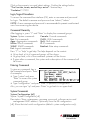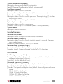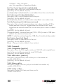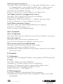
1
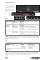
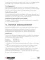
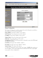
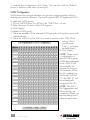
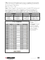
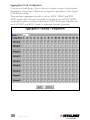
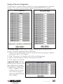
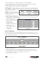
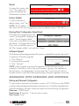
16/24-PORT
GIGABIT
ETHERNET
RACKMOUNT
MANAGED SWITCH
USER
MANUAL
MODEL 523547/523554
INT-523547/523554-UM-0107-01
CONTENTS
section
page
1. Introduction .......................................................................3
Front Panel............................................................................. .................4
Rear Panel................................................................ ...........................5
2. Installation ........................................................................5
Device Installation............................................................................. .......5
Network Cable Installation......................................................................6
3. Functions ............................................................................6
4. Switch Management .........................................................7
Managing through a Web Browser ............................................7
Managing with Command Line Interface .................................... 17
5. Specifications ..................................................................24
FCC STATEMENTS
FCC Warning
This equipment has been tested and found to comply with the limits for a Class A
digital device, pursuant to part 15 of the FCC Rules. These limits are designed to
provide reasonable protection against harmful interference when the equipment
is operated in a commercial environment. This equipment generates, uses and can
radiate radio frequency energy and, if not installed and used in accordance with
the instruction manual, may cause harmful interference to radio communications.
Operation of this equipment in a residential area is likely to cause harmful
interference, in which case the user will be required to correct the interference
at his own expense.
This device complies with Part 15 of the FCC Rules. Operation is subject to the
following two conditions: 1) This device may not cause harmful interference and
2) This device must accept any interference received, including interference that
may cause undesired operation.
CE Mark Warning
This equipment complies with the requirements relating to electromagnetic
compatibility, EN 55022 class A for ITE, the essential protection requirement
of Council Directive 89/336/EEC on the approximation of the laws of the
member states relating to electromagnetic compatibility.
2
CONTENTS
1. INTRODUCTION
Thank you for purchasing this INTELLINET NETWORK SOLUTIONS™
Gigabit Ethernet Rackmount Managed Switch, Model 523547 (16-port)
or Model 523554 (24-port). With its 10/100/1000 Mbps gigabit ports
and user-friendly Web-based management interface, this switch boosts
networking throughput to provide a real gigabit connection that makes
it possible to transfer large, high-bandwidth files with greater speed,
efficiency and reliability.
Refer to this user manual for complete setup and operation instructions, and
enjoy the benefits of these additional features:
• 10/100/1000 auto-sensing ports automatically detect optimal network speeds
• 4 SFP mini-GBIC transceiver module slots (use of an SFP port automatically
disables the connection of its corresponding copper port)
• All RJ-45 ports with Auto-MDIX (auto uplink) support
• Supports NWay Auto-Negotiation
• Store and forward switching architecture
• Full/half duplex operation
• IEEE 802.3x flow control for full duplex
• Zero packet loss back-pressure flow control for half duplex
• Non-blocking wire-speed forwarding and filtering
• Supports port controls (speed, flow control and maximum frame size)
• Broadcast storm control with multicast packet rate settings
• Supports VLAN (16-port version: 16 groups; 24-port version: 24 groups)
and trunking (16-port version: 8 groups; 24-port version: 12 groups)
• Supports Quality of Service (QoS) with 2 priority levels
• Supports port mirroring
• Supports jumbo frames up to 9 kBytes
• Packet filtering/forwarding rates: 1,488,000 pps (1000 Mbps), 148,800 pps
(100 Mbps), 14,880 pps (10 Mbps)
• Rugged metal housing for maximum durability
• Supports up to 8192 MAC address entries
• 340 kBytes buffer memory, 16-port version;
500 kBytes buffer memory, 24-port version
• Supports SNMP management
• Configuration via Web browser or RS-232 console port
• Includes 19” rackmount brackets
• Lifetime Warranty
Package Contents
• Gigabit Ethernet Rackmount Managed Switch
• Power cable
• User manual
INTRODUCTION
3
FRONT PANEL
Ports and LED indicators
are found on the front
panel of the switch. The
tables below explain
their purpose and
operation.
16-port
model
shown
LEDs
System LED
PWR
Status
Steady green
Off
Operation
Power on
Power off
Port LEDs
1000M
Status
Steady green
Blinking green
Operation
Valid port connection at 1000 Mbps
Valid port connection; data being transmitted/
received
No valid link or connected at 10/100 Mbps
Valid port connection at 10/100 Mbps
Valid port connection; data being transmitted/
received
No valid link or connected at 1000 Mbps
10/100M
Off
Steady green
Blinking green
Off
NOTE: The four mini-GBIC slots (A, B, C and D) share LED indicators with the
last four RJ-45 (copper) ports (i.e., ports 13–16 on the 16-port model and ports
21–24 on the 24-port model).
Ports
The auto-negotiation feature allows ports to operate in one of the following modes:
Media
10/100/1000 Mbps copper
Speed
10 Mbps
100 Mbps
1000 Mbps
1000 Mbps (fiber – mini-GBIC 1000 Mbps
required)
Duplex Mode
Half/Full Duplex
Half/Full Duplex
Full Duplex
Full Duplex
NOTE: For the last four (highest numbered) ports, when both the fiber (miniGBIC) and copper (RJ-45) interfaces are connected, the switch automatically
disables the copper port and activates the fiber interface.
4
INTRODUCTION
Restore Default Button
Use this button to reset the switch or restore factory default settings. To reset,
press the button once. To restore factory default settings, press and hold the
button for three seconds.
REAR PANEL
Power Receptacle
Plug the female end of the power cord firmly into the receptacle and the other
end into an electrical outlet. Confirm that the power LED is lit for a normal
power status.
2. INSTALLATION
DEVICE INSTALLATION
The Gigabit Ethernet Rackmount Managed Switch can be placed directly on
your desktop or mounted in a rack. Rackmounting facilitates orderly installation
when you are going to install a series of networking devices.
Prior to use, it is recommended that the device be placed/positioned:
• with a minimum of 25 mm of clearance on the top and sides for adequate
ventilation
• away from sources of electrical noise, such as radios, transmitters and
broadband amplifiers
• where it cannot be affected by excessive moisture
Desktop
1. Attach the included rubber feet to the bottom of the device to keep it from
slipping. The recommended positions are marked on the switch.
2. Place the device on a level surface that can support the weight of the switch
(and any other items that need to be considered).
Rackmount
1. Disconnect any cables from the switch before proceeding with rackmounting.
2. Place the device on a hard, flat surface with the front facing you.
3. Position one of the two included mounting brackets over the mounting holes
on one side of the unit.
4. Insert the screws and fully tighten them with a suitable screwdriver.
5. Repeat the two previous steps for the other side of the device.
6. Insert the switch into the rack (secure with suitable screws, if desired);
reconnect cables as needed.
INSTALLATION
5
NETWORK CABLE INSTALLATION
Crossover/Straight-Through Cable
All the ports on the Gigabit Ethernet Rackmount Managed Switch support
Auto-MDI/MDI-X functionality, so both crossover and straight-through cables can
be used to connect to PCs, routers, additional switches and other devices.
Cat3/4/5/5e UTP/STP Cable
Cat3/4/5/5e UTP/STP cables provide optimal performance when the proper
cable is matched to the required transmit/receive speed, as indicated below.
Media
10/100/1000 Mbps copper
1000 Mbps fiber (mini-GBIC
required
Speed
10 Mbps
100 Mbps
1000 Mbps
1000 Mbps
Recommended cable
Cat3/4/5 UTP/STP
Cat5 UTP/STP
Cat5/5e UTP/STP
Cable type depends on
the GBIC: Refer to the
mini-GBIC instructions.
3. FUNCTIONS
Jumbo Frames
With Jumbo Frames supported, the switch can transport data in fewer frames,
which helps prevent overheads, shortens processing time and reduces the
number of interruptions. NOTE: To enable Jumbo Frames, Flow Control should
be enabled first.
Flow Control and Back Pressure
Flow Control and Back Pressure both make it easier for lower-speed and
higher-speed devices to communicate with each other, ensuring that data
transmissions are correct. The 802.3x Flow Control and Back Pressure
mechanisms work for full and half duplex modes, respectively. Flow Control
can be enabled or disabled on a per-port basis.
Mirror
The Mirror function lets a network administrator monitor traffic by forwarding a
copy of the packets transferred by the monitored port to a “sniffer” port.
VLAN
With VLAN support, the network can be segmented into groups to reduce
collisions caused by heavy traffic among multiple devices. The switch supports
both port-based and 802.1Q tag-based VLAN. Port-based VLAN classifies
6
FUNCTIONS
incoming packets to VLANs according to their ingress port. The 802.1Q-based
VLAN adds a tag to the header of the packet to classify the VLANs.
Trunk (Aggregation)
The Trunk function integrates several ports to enlarge the bandwidth, which
helps boost the backbone connectivity. The switch allows a maximum of eight
(16-port) or twelve (24-port) groups, with eight members for each group.
Quality of Service (QoS)
QoS classifies packets based on precedence, which means the packets are
transmitted and received by their priorities. This helps high-bandwidth-demanded
applications such as VoIP to get an unobstructed connection.
Simple Network Management Protocol (SNMP)
This device is SNMP-supported, allowing it to be monitored or inspected by
an SNMP management station.
4. SWITCH MANAGEMENT
Advanced management options can be accessed through a Telnet session/
Internet browser over the network (in-band) or through a console port.
MANAGING THROUGH A WEB BROWSER
Authentication
To access the Web-based management interface, configure the management
station with an IP address and subnet mask compatible to the switch, which
has the following factory default settings:
IP address:
192.168.1.1
Subnet mask:
255.255.255.0
Default gateway: 192.168.1.254
1. Activate your Web browser and enter the above IP address in the Address
field.
2. Key in the username and password to authenticate. The factory default
value for both username and password is “admin.” Click “Apply.”
After authentication, the System Configuration page (shown on next page)
displays as the homepage. The complete Configuration menu — plus
Monitoring and Maintenance links — appears on the left side of each page
for access to all management functions.
MANAGEMENT
7
Gigabit Ethernet Rackmount Managed
System Configuration
The System Configuration window presents the switch information and allows
the configuration of the switch properties.
MAC Address: The MAC address of this device.
S/W Version: The software version of this device.
IP Address: Set up the IP address of the switch.
Subnet Mask: Set up the subnet mask of the switch.
Gateway: Set up the gateway of the switch.
Management VLAN: The VLAN group that is allowed to access the WEB-based
management interface.
Username: The login name. (default: “admin”)
Password: The login password. (default: “admin”)
System Name: The name of the device.
To save the configuration of the system, click “Apply.” NOTE: After applying a
new IP address, a new login page will be started automatically. Login again
to proceed to other configurations.
8
MANAGEMENT
*
Port Configuration
The Port Configuration page shows the link status of each port and allows the
configuration of speed, flow control and maximum frame size for each port.
Link: Shows the link status of each port. The column lights green with the link
speed while there is a valid connection to this port.
Mode: Select a speed for each port. “Auto Speed” enables auto-negotiation;
“Disable” stops the port from functioning.
Flow Control: Check the boxes to enable FDX flow control; uncheck to disable.
Max Frame: Adjust the size of jumbo frames. The set length is 1518 bytes; the
maximum value can be up to 9216 bytes.
* 16-port images are used throughout this user manual. 24-port images show identical information.
MANAGEMENT
9
To save the port configuration, click “Apply.” You can also click the “Refresh”
button to see the current status of each port.
VLAN Configuration
VLAN divides the network members into groups to reduce packet collisions
and improve network efficiency. The switch supports 802.1Q tag-based VLAN.
To add new VLAN groups:
1 Fill in a VLAN ID from 2 to 4094 in the “VLAN\Port” column.
2. Select the ports for each of the VLAN groups.
3. Click “Apply.”
To delete a VLAN group:
1. Clear the members of the selected VLAN group by clicking those ports with
checked boxes.
2. Clear the VLAN ID of the VLAN you want to remove in the “VLAN\Port”
column. (Don’t
actually enter
“NA” — just leave
the field blank.)
3. Click “Apply.”
NOTE: When a port
is configured to a
specific VLAN group,
a PVID that corresponds
to the VLAN ID will
automatically be
assigned to this port.
(For example: When
Port 3 is added to a
VLAN with VLAN ID
“2,” the PVID “2” will
be automatically
assigned to Port 3.)
NOTE: The VLAN,
Port Aggregation and
Mirror settings are
correlative. Make sure
that the settings won’t
influence each other.
10
MANAGEMENT
PVID: When the VLAN-enabled switch receives a tagged packet, the packet
will be sent to the port’s default VLAN according to the PVID (port VLAN ID) of
the receiving port. (See below.)
Port: Ports 1–16 or 1–24.
Egress: Select “tagged” in the drop-down menu to enable PVID checking and
tag inserting of one port; select “untagged” to cancel. For example, if an
Egress-tagged port receives an untagged frame, it will be transmitted as a
PVID-tagged frame. For detailed tagging status, refer to the following table:
Untagged
Packet Frames In Packet Frames Out
Untagged
Untagged
Tagged
Untagged
Pre-tagged
Untagged
Tagged
Packet Frames In Packet Frames Out
Untagged
Tagged (PVID)
Tagged (VID)
Tagged (VID)
Pre-tagged
Tagged (PVID)
PVID: Port VLAN ID
(1–4094).
Only tagged: “Enable”
blocks all un-tagged
packets from accessing
this port; “Disable”
allows all packets to
access this port.
MANAGEMENT
11
Aggregation/Trunk Configuration
To set up port trunk groups, click in the ports’ number columns on the desired
Aggregation Group row (1–8) per the configuration grid below. Click “Apply”
to save each setting.
There are three aggregation modes to set up: SMAC, DMAC and XOR.
SMAC mode selects the path of packets according to source MAC. DMAC
mode selects paths according to destination MAC. XOR mode calculates the
result of DMAC and SMAC modes to determine the path of packets.
12
MANAGEMENT
Quality of Service Configuration
QoS enhances communication quality by assigning precedence to classified
packets. This switch has port-based, tag-based and DSCP QoS modes:
Port-based mode: Allows users to configure certain ports as high or low
priority. To assign a priority level for each port:
1. Select “Port” in the Mode column for those ports that are going to perform
port-based QoS. Click “Apply.”
2. Click “Port priority” to display the Port Priority Setting page.
3. Click on the drop-down menu to specify priority levels.
4. Click “Apply” to execute.
Tag-based mode: Decides
packet priority based on the
tags added to the packets.
For tag-based configuration:
1. Select “Tagged” in the
Mode column for those
ports that are going to
perform tag-based QoS.
Click “Apply.”
MANAGEMENT
13
2. Click “Tag priority” to display the Tag Priority Setting page.
3. From the drop-down menu, select the port you are going to configure.
4. Select “high” or “low” for each Priority Tag setting.
5. Click “Apply” again to execute the configuration.
DSCP mode: Assigns packet priority based on the types of incoming packets
(shown below), as distinguished by delay, throughput and reliability information
attached to the packet.
Bit 0
Bit 1
Bit 2
(Delay)
(Throughput) (Reliability)
NOTE: The switch distinguishes
packets with DSCP precedence 0 (Normal)
0 (Normal)
0 (Normal)
1 (Low)
1 (High)
1 (High)
“000(routine)” only.
For DSCP-based configuration:
1. Select “DSCP” in the Mode column for those ports that are going to perform
DSCP-based QoS. Click “Apply.”
2. Click “DSCP priority” to
display the DSCP Priority
Setting page.
3. Assign priorities as
“high” or “low” for each
precedence type.
4. Click “Apply” again to
execute the
configuration.
Mirror Configuration
The Mirror function copies all the packets that are transmitted by the source
port to the destination port, allowing administrators to analyze and monitor the
traffic of the monitored ports.
For Mirror configuration:
1. Select the ports to be monitored by checking their Monitor Port boxes.
2. In the drop-down menu in the Sniffer Port section, select a port to serve as
the administration port for monitoring the source ports.
3. Click “Apply” to activate.
14
MANAGEMENT
Rate Limit Configuration
Rate Limit manages the bandwidth
for each port and presents the
settings options for Storm Control,
which limits the flow rates of
broadcast and multicast
transmission.
To activate Storm Control:
1. Click on the drop-down menu
to specify a speed for each
frame type.
2. Click “Apply” to execute the
configuration.
SNMP Configuration
The Gigabit Ethernet Rackmount Managed Switch supports SNMP management,
which allows network administrators to monitor and configure this device with
SNMP software.
To enable SNMP
management of the switch:
1. Select “Enable” on the
drop-down menu.
2. Specify a trap IP. (A
trap IP is the destination
port for sending trap information, which is usually the IP address of network
administrators.)
3. Enter a name in the Community Get field. This will be the password for
accessing the management information base (MIB) with read-only authority.
4. Enter a name in the Community Set field. This will be the password for
accessing the MIB with both read and write authority.
Discovery
If installing a series of switches, the Discovery management tool helps in
searching for and accessing switches within the LAN.
NOTE: Discovery features a list of the 16 devices (maximum) for auto and
manual modes.
MANAGEMENT
15
To initiate Auto Search:
1. Click “Apply” to list
the found devices.
2. Click the IP address
hyperlink to access
the device.
To use Manual Add:
1. Enter the IP address and name in the text fields.
2. Click “Add” to add the new IP address in the table.
To use Manual Delete:
1. Check the box of the device to be removed.
2. Click “Delete.”
Statistics Overview
The Statistics Overview
page is provided in
order to determine the
general transmitting
and receiving status
of each port (vs. the
detailed port status
explained below).
Click “Clear” to clear
all statistics; click
“Refresh” to renew the statistics.
Detailed Statistics
The Detailed Statistics page is provided in order to determine the detailed
transmitting and receiving status of each port.
Click on any of the hyperlinks above to select a particular port. Click “Clear”
to clear all statistics; click “Refresh” to renew the statistics.
16
MANAGEMENT
Restart
To restart the system, click
“Yes.” The system will
restart and display the
Authentication window. As before, enter the username and password to continue.
Factory Default
To restore the factory
default values, click “Yes.”
NOTE: The IP address of
the switch will also be configured as a factory-default setting: 192.168.1.1.
Booting Flash Configuration (Smart Boot)
The Smart Boot page presents the
switch’s booting flash configuration
option. ”Active image number”
shows the current flash for booting
the device. To change the booting
flash, click on the flash version in
the “Boot image number” row and click “Apply.”
Software Upload
The Software Upload page presents the option to upgrade firmware for the switch.
To perform a firmware upgrade:
1. Click “Browse.”
2. Locate the firmware file.
3. Click “Upload.”
NOTE: New firmware is going to be applied on the flash that was not
selected in Smart Boot; that is, the new firmware is going to be applied on
the flash that is not designated as the booting flash. Ensure that the switch is
booted with the correct flash before performing a firmware upgrade of any kind.
MANAGING WITH COMMAND LINE INTERFACE
Startup and Terminal Configuation
To start up the command line interface, connect a PC COM port to the RS-232
connector and activate terminal emulation software such as Windows HyperTerminal.
Terminal emulation software should be started with the following configuration:
Data rate: 115200 baud
Data format: 8 data bits, 1 stop bit and no parity
Flow control: none
MANAGEMENT
17
Click on the property icon and select settings. Confirm the settings below.
“The Function, arrow, and ctrl keys act as”: Terminal keys
”Emulation”: VT100
Login/Logout Procedures
To access the command line interface (CLI), enter a username and password
for login. The default username and password are “admin”/”admin.”
NOTE: A new username and password is recommended to prevent unauthorized
users from accessing the device.
Command Hierarchy
After logging in, press “?” and “Enter” to display the command groups.
System: System commands
Port: Port commands
Aggr: Aggregation commands
Mirror: Mirror commands
SNMP: SNMP commands
Exit: Logout commands
Console: Console commands
VLAN: VLAN commands
QoS: QoS commands
IP: IP commands
Ratelimit: Rate setup commands
Press “?” or “help” to get help. The help depends on the context:
• At top level, a list of command groups will be shown.
• At group level, a list of the command syntaxes will be shown.
• If given after a command, the syntax and a description of the command will
be shown.
Entering Commands
To give any command, key in
the command and press “Enter.”
As examples:
• Type “system” and press
“Enter” to access the system
command group.
• Type “configuration” and press “Enter” to perform a configuration.
Also, you can type “up” and press “Enter” to go back to an upper level.
System Commands
System Configuration [all]
Syntax: System Configuration [all]
Description: Show systemname, username, password, software version and
management MAC address. Optionally show the full configuration.
[all]: Show the total switch configuration (default: system configuration only).
18
MANAGEMENT
System Restore Default [keepIP]
Description: Restore factory default configuration.
[keepIP]: Preserve IP configuration (default: not preserved).
UserName [<name>]
Description: Set or show the username.
[<name>]: String of up to 16 characters (default: show username).
System Password [<password>]
Description: Set or show the console password. The empty string (“”) disables
the password check.
[<password>]: Password string of up to 16 characters.
System Systemname [<name>]
Description: Set or show the system name.
[<name>]: String of up to 16 characters (default: show systemname).
System Reboot
Description: Reboot the switch.
Console Commands
Console Configuration
Description: Show configured console prompt and timeout.
Console Timeout [<timeout>]
Description: Set or show the console inactivity timeout in seconds. The value
zero disables timeout.
[<timeout>]: Timeout value: 0, 60-10,000 seconds.
Console Prompt [<prompt_string>]
Description: Set or show the console prompt string.
[<prompt_string>]: Command prompt string of up to 10 characters.
Port Commands
Port Configuration [<portlist>]
Description: Show the configured and current speed, duplex mode, flow control
mode and admin state for the port.
[<portlist>]: Port list (default: all ports).
Port Mode [<portlist>] [<mode>]
Description: Set or show the speed and duplex mode for the port.
[<portlist>]: Port list (default: all ports).
[<mode>]: Port speed and duplex mode (default: show configured and current
mode).
10hdx: 10 Mbps, half duplex.
10fdx: 10 Mbps, full duplex.
100hdx: 100 Mbps, half duplex.
100fdx: 100 Mbps, full duplex.
MANAGEMENT
19
1000fdx: 1 Gbps, full duplex.
auto: Auto negotiation of speed and duplex.
Port Flow Control [<portlist>] [enable|disable]
Description: Set or show flow control mode for the port.
[<portlist>]: Port list (default: all ports).
[enable|disable]: Enable/disable flow control (default: show flow control mode).
Port Admin [<portlist>] [enable|disable]
Description: Set or show the admin state for the port.
[<portlist>]: Port list (default: all ports).
[enable|disable]: Enable or disable admin state (default: show admin state).
Port MaxFrame [<portlist>] [<framesize>|reset]
Description: Set or show the maximum frame size in bytes (including FCS) for
frames received on the port. Tagged frames are allowed to be 4 bytes
longer than the maximum frame size. Use the reset option to return to default
setting.
[<portlist>]: Port list (default: all ports).
[<framesize>|reset]: Maximum frame size [1518 – 9216] or reset to 1518 bytes
(default: show maximum frame size).
NOTE: To make the maxframe larger than 1518, [Flow Control] should be enabled.
Port Statistics [<portlist>] [clear]
Description: Show or clear statistics for the port.
[<portlist>]: Port list (default: all ports).
[clear] : Clear port statistics (default: show statistics).
VLAN Commands
VLAN Configuration [<portlist>]
Description: Show the VLAN egress mode, port VLAN ID and accepted frame
type for the port and the permanently stored VLAN table.
[<portlist>]: Port list (default: all ports).
VLAN Add <vidlist> [<portlist>]
Description: Add VLAN entry and include ports in the member set.
<vidlist>: VLAN ID list.
[<portlist>]: Port list (default: all ports).
VLAN Delete <vidlist>
Description: Delete VLAN entry (all ports excluded from member set).
<vidlist>: VLAN ID list.
VLAN Lookup <vidlist>
Description: Lookup VLAN entry and show port list.
<vidlist>: VLAN ID list.
20
MANAGEMENT
VLAN Egress [<portlist>] [untagged|tagged]
Description: Set or show the VLAN egress mode setting for the port. Egress
untagged ports will strip the VLAN tag from received frames. Egress tagged
ports will not strip the tag from received frames.
[<portlist>]: Port list (default: all ports).
[tagged|untagged]: (default: show egress tag setting).
VLAN PVID [<portlist>] [<vid>|none]
Description: Set or show the port VLAN ID. Untagged frames received on the
port will be classified to this VLAN ID. Frames classified to this VLAN ID will
be sent untagged on the port.
[<portlist>]: Port list (default: all ports).
[<vid>|none]: Port VLAN ID, 1 – 4094 (default: show PVID). The “none” option
can be used for trunk links.
VLAN OnlyTag [<portlist>] [enable|disable]
Description: Set or show the onlytag setting of this port.
[<portlist>]: Port list (default: all ports).
[enable|disable]: Only accept tagged frame or not (default: show disable).
Aggregation Commands
Aggr Configuration
Description: Shows the aggregation groups and the aggregation mode.
Aggr Delete <portlist>
Description: Delete link aggregation group.
<portlist>: Port list. Aggregations including any of the ports will be deleted.
Aggr Lookup <portlist>
Description: Look up and display link aggregation group.
<portlist>: Port list. Aggregations including any of the ports will be shown.
Aggr Mode [smac|dmac|xor]
Description: Set or show link aggregation traffic distribution mode.
[smac|dmac|xor]: Aggregation mode, SMAC, DMAC or XOR (default: show
mode).
QoS Commands
QoS Configuration [<portlist>]
Description: Show the configured QoS mode and the priority setting of all ports.
[<portlist>]: Port list (default: all ports).
QoS Mode [<portlist>] [tag|port|diffserv]
Description: Set or show the QoS mode for the port.
[<portlist>]: Port list (default: all ports).
[tag|port|diffserv]: Enable the class of service — tag, port or IP differentiated
services — for the port (default: show mode).
MANAGEMENT
21
QoS Port [<portlist>] [<class>]
Description: Set or show the port class. In tag mode, the default class is used
for untagged frames. In port mode, the default class is used as the port
priority. In diffserv mode, the default class is used for non-IP frames.
[<portlist>]: Port list (default: all ports).
[<class>]: Internal class of service (default: show default class).
QoS Tagprio [<portlist>] [<tagpriolist>] [<class>]
Description: Set or show the VLAN user priority mapping.
[<portlist>]: Port list (default: all ports).
[<tagpriolist>]: VLAN user priority list, 0 – 7 (default: all user priorities).
[<class>]: Internal class of service (default: show class).
QoS DiffServ [<dscpno>] [<class>]
Description: Set or show the IP Differentiated Services mapping.
[<dscpno>]: IP DSCP number, 0 – 7.
[<class>]: range: low|normal|medium|high.
Mirror Commands
Mirror Configuration
Description: Show the mirror destination port and mirror mode for source ports.
Mirror Port [<port>]
Description: Set or show the mirror destination port.
[<port>]: Mirror destination port (default: show mirror port).
Mirror Source [<portlist>] [enable|disable]
Description: Set or show the source port mirror mode.
[<portlist>]: Source port list (default: all ports).
[enable|disable]: Enable/disable mirroring of frames received on port (default:
show mirror mode).
IP Commands
IP Configuration
Description: Show IP-configured IP address, mask, gateway, VLAN ID and mode.
IP Setup
Description: Setup or show IP configuration.
[<ipaddress>]: IP address (default: show IP configuration).
[<ipmask>]: IP subnet mask (default: subnet mask for address class).
[<ipgateway>]: Default IP gateway (default: 0.0.0.0).
[<vid>]: VLAN ID, 1 – 4094 (default: 1).
IP Web management
Description: Activate or deactivate the Web management.
[enable|disable]: Enable/disable Web management. (default: show Web
management).
22
MANAGEMENT
SNMP Commands
SNMP Configuration
Description: Show the SNMP configuration.
SNMP Community [<get>|<set>] [<community>]
Description: Set or show community setting for SNMP.
[<get>|<set>]: Community for get or set.
[community]: Community string.
SNMP Setup [enable|disable]
Description: Activate or deactivate the SNMP.
[enable|disable]: Enable/disable SNMP (default: show SNMP mode).
SNMP Trap [<IP Address>]
Description: Set or show SNMP traps destination.
<IP Address>: IP address to send traps to. (default: show trap configuration).
Ratelimit Commands
Ratelimit Configuration
Description: Show the Ratelimit setting.
Ratelimit Setup <traffic type > <option>
Description: Set or show the ratelimit configuration. The allowed frame rates for
ICMP frames, learn frames, multicasts, broadcasts and flooded unicasts are
controlled using a central ratelimit.
[<traffic type>]: Ratelimit to set. Can be one of: [ICMP|Broadcast|Multicast]
(default: show all).
[enable|disable]: Enable or disable specified ratelimit.
[<rate>]: Frame rate in kiloframes. Allowed values: 1k, 2k, 4k, 8k, 16k, 32k, 64k.
Ratelimit Egress [<portlist>] [enable|disable] [<rate>]
Description: Set or show the egress configuration.
[<portlist>]: Port list (default: all ports).
[enable|disable]: Enable or disable egress.
[<rate>]: Disable or set leaky bucket rate in kbps
[128/256/512/1024/2048/3072k] (default: show egress rate).
Ratelimit Ingress[<portlist>] [enable|disable] [<rate>]
Description: Set or show the ingress configuration.
[<portlist>]: Port list (default: all ports).
[enable|disable]: Enable or disable ingress.
[<rate>]: Disable or set leaky bucket rate in kbps
[128/256/512/1024/2048/3072k] (default: show ingress rate).
MANAGEMENT
23
5. SPECIFICATIONS
Standards
•
•
•
•
•
•
•
IEEE 802.3 (10Base-T Ethernet)
IEEE 802.3u (100Base-TX Fast Ethernet)
IEEE 802.3ab (Twisted Pair Gigabit Ethernet)
IEEE 802.1p (traffic prioritization)
IEEE 802.1q (VLAN)
IEEE 802.3x (flow control, for full duplex mode)
SNMPv1 (Simple Network Management Protocol)
General
• Media support:
- 10Base-T Cat3, 4, 5 UTP/STP RJ-45
- 100Base-TX Cat5 UTP/STP RJ-45
- 1000Base-T Cat5e UTP/STP RJ-45
• Packet filter/forwarding rate:
- 1,488,000 pps (1000 Mbps)
- 148,800 pps (100 Mbps)
- 14,880 pps (10 Mbps)
• Buffer memory: 340 kBytes, 16-port version: 500 kBytes, 24-port version
• MAC address table: 8192 entries
• Backplane speed: 32 Gbps, 16-port version: 48 Gbps, 24-port version
• Switch architecture: store and forward
• Ports, 16-port version
- 16 x RJ-45 Gigabit Ethernet ports
- 4 SFP Mini-GBIC transceiver module slots
• Ports, 24-port version
- 24 x RJ-45 Gigabit Ethernet ports
- 4 SFP Mini-GBIC transceiver module slots
• Modes, 16-port version
- 16 x RJ-45 ports
- 15 x RJ-45 ports and 1 x SFP mini-GBIC transceiver module
- 14 x RJ-45 ports and 2 x SFP mini-GBIC transceiver modules
- 13 x RJ-45 ports and 3 x SFP mini-GBIC transceiver modules
- 12 x RJ-45 ports and 4 x SFP mini-GBIC transceiver modules
• Modes, 24-port version
- 24 x RJ-45 ports
- 23 x RJ-45 ports and 1 x SFP mini-GBIC transceiver module
- 22 x RJ-45 ports and 2 x SFP mini-GBIC transceiver modules
- 21 x RJ-45 ports and 3 x SFP mini-GBIC transceiver modules
- 20 x RJ-45 ports and 4 x SFP mini-GBIC transceiver modules
• Certifications: FCC Class A, CE Mark, VCCI Class A, RoHS
24
SPECIFICATIONS
Configuration Options
•
•
•
•
•
Full and half duplex per port
Port link speed: 10 Mbps, 100 Mbps, 1000 Mbps or auto-negotiation
Port bandwidth control: Disable/128/256/512/1024/2048/3072 kbps
VLAN: Tag based, up to 16 groups (16-port); up to 24 groups (24-port)
Quality of Service (QoS): 2 priority levels and port-based ratio controlling
the ratio between high and low priority
• Port Mirroring for all ports with sniffer port configuration
• Port Aggregation/Trunking for all ports, 8 groups (16-port) or
12 groups (24-port)
• SNMP Management (enable/disable, trap IP, community get and set)
LEDs
• Power
• Link/Act: 1000 Mbps, 10/100 Mbps
Power
• Internal power supply, 100 to 240 V AC, 50/60 Hz
• Power consumption: 14.5 Watts (maximum, 16-port);
21.2 Watts (maximum, 24-port)
Environmental
•
•
•
•
•
•
Metal housing, 19” rackmount, 1 U
Dimensions: 441 (W) x 130 (L) x 44 (H) mm (17.4 x 5.1 x 1.7 in.)
Weight: 2.5 kg (5.4 lbs.
Operating temperature: 0° to 40°C (32° to 104°F)
Operating humidity: 10% to 90% RH, non-condensing
Storage temperature: -10° to 80°C (-14° to 176°F)
Package Contents
• Gigabit Ethernet Rackmount Managed Switch
• Power cable
• User manual
SPECIFICATIONS
25
NOTES
26
NOTES
27
www.intellinet-network.com
Are you completely satisfied with this product?
Please contact your INTELLINET NETWORK SOLUTIONS™ dealer
with comments or questions.
Copyright © INTELLINET NETWORK SOLUTIONS
All products mentioned are trademarks or registered trademarks of their respective owners.