1
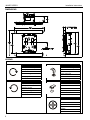
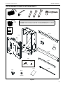
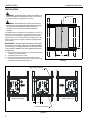
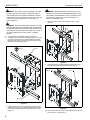
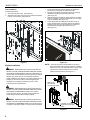
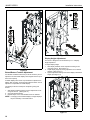
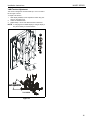
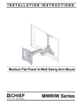
INSTALLATION INSTRUCTIONS
Instrucciones de instalación
Installationsanleitung
Instruções de Instalação
Istruzioni di installazione
Installatie-instructies
Instructions d´installation
Medium Flat Panel In-Wall Mount
Spanish Product Description
German Product Description
Portuguese Product Description
Italian Product Description
Dutch Product Description
French Product Description
MIWRF SERIES
MIWRF SERIES
DISCLAIMER
Milestone AV Technologies, and its affiliated corporations and
subsidiaries (collectively, "Milestone"), intend to make this
manual accurate and complete. However, Milestone makes no
claim that the information contained herein covers all details,
conditions or variations, nor does it provide for every possible
contingency in connection with the installation or use of this
product. The information contained in this document is subject
to change without notice or obligation of any kind. Milestone
makes no representation of warranty, expressed or implied,
regarding the information contained herein. Milestone assumes
no responsibility for accuracy, completeness or sufficiency of
the information contained in this document.
Chief® and ClickConnect™ are trademarks of Milestone AV
Technologies. All rights reserved.
IMPORTANT WARNINGS AND
CAUTIONS!
Installation Instructions
NOTES:
•
SUITABLE FOR USE IN OTHER
ENVIRONMENTAL AIR SPACE IN
ACCORDANCE WITH SECTION 300.22, (C)
OF THE NATIONAL ELECTRICAL CODE.
•
The equipment shall be installed and
assembled by qualified service personnel.
•
The maximum specified ambient temperature
of the cabinet system is 40° - 120°F (4° - 49°).
•
Minimum spacings between the accessories
and components and the housing for
Information Technology Communication
Equipment shall be maintained for safe
operation of the equipment when installed in
accordance with the National Electric Code,
ANSI/NFPA 70-1999. Refer to communication
equipment manufacturer’s specifications for
minimum spacings.
MIWRF Series contains the following models:
WARNING: A WARNING alerts you to the possibility of
serious injury or death if you do not follow the instructions.
CAUTION: A CAUTION alerts you to the possibility of
damage or destruction of equipment if you do not follow the
corresponding instructions.
WARNING: Failure to read, thoroughly understand, and
follow all instructions can result in serious personal injury,
damage to equipment, or voiding of factory warranty! It is the
installer’s responsibility to make sure all components are
properly assembled and installed using the instructions
provided.
WARNING: Failure to provide adequate structural strength
for the installation of this kit can result in serious personal
injury or damage to equipment! It is the installer’s
responsibility to make sure the structure to which this kit is
attached can support five times the combined weight of all
equipment. Reinforce the structure as required before
installing the component. The wall to which the mount is
being attached may have a maximum drywall thickness of
5/8" (1.6cm).
WARNING: Exceeding the weight capacity can result in
serious personal injury or damage to equipment! It is the
installer’s responsibility to make sure the combined weight of
all components attached to this accessory does not exceed
125 lbs (57 kg).
2
•
MIWRF
•
MIWRFUB
•
MIWRFVB
MIWRF SERIES
Installation Instructions
DIMENSIONS
LEGEND
Tighten Fastener
Hex-Head Wrench
Apretar elemento de fijación
Llave de cabeza hexagonal
Befestigungsteil festziehen
Sechskantschlüssel
Apertar fixador
Chave de cabeça sextavada
Serrare il fissaggio
Chiave esagonale
Bevestiging vastdraaien
Zeskantsleutel
Serrez les fixations
Clé à tête hexagonale
Loosen Fastener
Open-Ended Wrench
Aflojar elemento de fijación
Llave de boca
Befestigungsteil lösen
Gabelschlüssel
Desapertar fixador
Chave de bocas
Allentare il fissaggio
Chiave a punte aperte
Bevestiging losdraaien
Steeksleutel
Desserrez les fixations
Clé à fourche
Adjust
Ajustar
Einstellen
Ajustar
Regolare
Afstellen
Ajuster
3
Installation Instructions
MIWRF SERIES
TOOLS REQUIRED FOR INSTALLATION AND PARTS
1/2"
1/8"
7/16"
9/16"
1"
NOTE:
Listed MSBU interface bracket provided with Listed Model MIWRFUB, but not shown.
Listed MSBV interface bracket provided with Listed Model MIWRFVB, but not shown.
I/M
B (2)
x1
A (1)
C (4)
D (4)
E (2)
F (1)
F1 (4)
F2 (4)
5/16" x 2-1/2"
5/16"
G (2)
L (4)
J (8)
H (8)
K (4)
5/16-18
Figure 1
4
MIWRF SERIES
Installation Instructions
INSTALLATION
WARNING: IMPROPER INSTALLATION CAN RESULT IN
DEATH OR SERIOUS PERSONAL INJURY! This accessory
should be installed by qualified personnel only.
Cutout Area
WARNING: IMPROPER INSTALLATION CAN LEAD TO
MOUNT FALLING CAUSING SEVERE PERSONAL INJURY
OR DAMAGE TO EQUIPMENT! DO NOT deviate from
installation instructions provided. DO NOT substitute
hardware.
The MIWRF Series is designed to accommodate up to 3-1/2" of
lateral shift adjustment (right or left display offset from center of
studs). This is accomplished by aligning the upper and lower
mounting studs on the housing with either the right hand or left
hand mounting holes in the upper and lower mounting brackets.
(See Figure 3)
15"
IMPORTANT ! : Using the lateral shift feature will impact
the location of the Listed J-Box [not included] installation
on the housing. If housing lateral shift is used any Listed
J-box must be installed to the side opposite the direction
of adjustment.
1.
2.
3.
4.
Determine desired mounting location and locate studs using
a stud finder or similar method.
Accurately locate center of studs.
Determine desired lateral shift required. (See Figure 3)
Using a level mark housing opening location on wall using
the dimensions identified. (See Figure 2)
7.65"
Figure 2
Upper Mounting Bracket
1
1
1
(Display Offset Left)
(Display Offset Right)
3-1/2"
Lower Mounting Bracket
Figure 3
5
MIWRF SERIES
Installation Instructions
WARNING: ELECTRICAL SHOCK HAZARD! CUTTING
WARNING: IMPROPER INSTALLATION CAN LEAD TO
OR DRILLING INTO ELECTRICAL WIRES OR CABLES
CAN CAUSE DEATH OR SERIOUS PERSONAL INJURY!
ALWAYS make certain area behind mounting surfaces is free
of electrical wires and cables before cutting, drilling, or
installing fasteners.
MOUNT FALLING CAUSING SEVERE PERSONAL INJURY
OR DAMAGE TO EQUIPMENT! Wiring of equipment must
be performed by properly trained and certified persons
following all applicable codes.
8.
Slide mount (A) enclosure into opening in wall.
Figure 5)
WARNING: EXPLOSION AND FIRE HAZARD! CUTTING
OR DRILLING INTO GAS PLUMBING CAN CAUSE DEATH
OR SERIOUS PERSONAL INJURY! ALWAYS make certain
area behind mounting surfaces is free of gas, water, waste, or
any other plumbing before cutting, drilling, or installing
fasteners.
5.
6.
(See
(A) x 1
8
Cut drywall on outside edge of lines and remove.
Assemble upper and lower mounting rails (B) to mount (A)
in slots that correspond to the desired lateral shift offset
identified during step 3 above using four flanged nuts (K).
(See Figure 3) and (See Figure 4)
(A) x 1
(K) x 4
6
Figure 5
9.
Place spacers (C) provided between wall and upper and
lower mounting rails (B) if required. (See Figure 6)
(B) x 2
(C) x 4
6
8
(B) x 2
Figure 4
7.
6
Install Listed J-box(s) [not included] and route all in-wall
cables and wiring to mount enclosure keeping in mind the
lateral shift offset determined during Step 3 above. (See
Figure 3)
Figure 6
10. Secure mount to studs using four flat washers (F2) and four
lag screws (F1). (See Figure 7)
MIWRF SERIES
Installation Instructions
Cover and Trim Installation
Cover Installation
To install covers:
(F1) x 4
(F2) x 4
1.
2.
3.
9
(A) x 1
Install upper and lower wall channel covers (E) by tipping
cover top down and positioning as shown in end view of
figure below. (See Figure 8)
Tap firmly across bottom of channels to lock in place as
shown in figure below. (See Figure 8)
Install four R.H. and L.H. end caps (D) by aligning tabs on
end caps (D) with slots in wall channel covers (E) and
sliding tabs in until end caps (D) are flush with wall channel
covers (E). (See Figure 8)
9
Figure 7
2
(E) x 2
(D) x 4
1
1
2
1
2
Figure 8
7
MIWRF SERIES
Installation Instructions
1.
Trim Installation
To install optional trim;
1.
2.
2.
Orient two trim pieces (G). (See Figure 9)
Slide slat in trim edge over lip in mount enclosure and press
trim (G) onto enclosure. (See Figure 9)
(G) x 2
3.
4.
Install Listed interface bracket following the installation
instructions provided with the interface bracket.
Move mount faceplate to extended position by grasping
faceplate and pulling outward away from wall.
(See Figure 10)
While supporting both sides of display, align four mounting
buttons on display or interface bracket with four mounting
holes in faceplate. (See Figure 10)
Lower display into place listening for audible "click" to
ensure recessed area of mounting buttons are properly
seated in lower area of mounting holes and "click lock"
mechanism has engaged. (See Figure 10) and
(See Figure 11)
4
2
2
1
3
Figure 9
Display Installation
WARNING: IMPROPER INSTALLATION CAN LEAD TO
MOUNT FALLING CAUSING SEVERE PERSONAL INJURY
OR DAMAGE TO EQUIPMENT! DO NOT install display in a
manner other than that specified by the manufacturer. Certain
displays may require the use of an interface bracket for
proper installation of the display. If an interface bracket is not
installed, or there are any other questions regarding the
installation of the display, immediately contact a Chief
Customer Service representative.
Figure 10
NOTE: Holes are provided in the faceplate for use with a
padlock or similar locking device, if desired. In addition,
the pin and nut may be removed from the upper holes
and moved to the lower holes for use as a more
permanent locking device. (See Figure 11)
Remove pin
4
and nuts and
move to lower holes.
WARNING: IMPROPER INSTALLATION CAN LEAD TO
MOUNT FALLING CAUSING SEVERE PERSONAL INJURY
OR DAMAGE TO EQUIPMENT. Displays can weigh in
excess of 40 lbs (18.1kg). ALWAYS use two people and
proper lifting techniques when installing display.
5
WARNING: IMPROPER INSTALLATION CAN LEAD TO
MOUNT FALLING CAUSING SEVERE PERSONAL INJURY
OR DAMAGE TO EQUIPMENT. Make sure mounting buttons
on display are properly seated in mounting holes in faceplate.
A padlock or bolt may
be placed through latch
holes
Figure 11
8
Installation Instructions
MIWRF SERIES
ADJUSTMENTS
CABLE MANAGEMENT
Pitch Tension Adjustment
WARNING: IMPROPER INSTALLATION CAN LEAD TO
SERIOUS PERSONAL INJURY OR DAMAGE TO
EQUIPMENT! Make sure cables do not run through pinch
points.
1.
Locate and install cable tie clips (J) where desired for proper
cable routing. (See Figure 12)
To adjust display pitch tension:
1.
2.
3.
With display installed, tighten or loosen two screws, one on
each side. (See Figure 14)
Check for desired tension.
Repeat Steps 1 and 2 until desired tension is obtained.
1
1
(J) x 8
Figure 12
2.
3.
Route cables down arms on mount. (See Figure 13)
Position cable covers (L) over arm and cable and press
cable covers (L) down onto arms to secure cables. (See
Figure 13)
WARNING: IMPROPER INSTALLATION CAN LEAD TO
SERIOUS PERSONAL INJURY OR DAMAGE TO
EQUIPMENT! DO NOT route cables through holes in
faceplate.
Figure 14
Roll Adjustment
The mount allows for the horizontal alignment (Roll) of the
display to be adjusted up to 2° right or left to level the display
after installing.
To adjust Roll:
2
1.
Loosen the roll tension adjustment nut located on the back
side of the faceplate assembly. (See Figure 15)
2. Level display.
NOTE: If display will not level slightly loosen top nut as well.
3
3.
(L) x 4
Tighten roll tension adjustment nut. (See Figure 15)
From Display
Figure 13
9
MIWRF SERIES
Installation Instructions
2
1
1
(on back side
in this view)
3
2
Figure 16
Display Height Adjustment
The mount is designed to accommodate up to 1" of display
height adjustment.
To adjust display height:
1.
Figure 15
Extend/Retract Tension Adjustment
Arm Extend and Retract tension is pre-set at the factory and is
adjusted to accommodate displays with weights near the top of
the mounts capacity.
2.
3.
With display installed, loosen adjustment locking screw
using hex wrench. (See Figure 17)
Adjust display height by turning adjustment nut in desired
direction. (See Figure 17)
Tighten adjustment locking screw when display is at desired
height. (See Figure 17)
If smaller displays are used it may be difficult to reposition the
display after mounting. Arm Extend and Retract tension can be
adjusted to compensate for smaller display.
1
The display must be mounted prior to adjusting swing arm
tension.
3
1.
With display installed, tighten or loosen adjustment screw
using hex wrench. (See Figure 16)
2. Check for desired tension.
3. Repeat Steps 1 and 2 until desired tension is obtained.
NOTE: If changing from a smaller display to a larger display it
may be necessary to increase tension.
2
Figure 17
10
Installation Instructions
MIWRF SERIES
YAW Tension Adjustment
The mount is designed to accommodate up to 37.5° of travel to
left and right of center.
To adjust YAW tension:
1.
With display installed, loosen adjustment screw using hex
wrench. (See Figure 18)
2. Check for desired tension.
3. Repeat Steps 1 and 2 until desired tension is obtained.
NOTE: If changing from a smaller display to a larger display it
may be necessary to increase tension.
1
3
TOP VIEW
Figure 18
11
MIWRF SERIES
Installation Instructions
USA/International
Chief Manufacturing, a products division
of Milestone AV Technologies
Europe
Asia Pacific
8805-000249 RevB
2009 Milestone AV Technologies, a
Duchossois Group Company
www.chiefmfg.com
11/09
A
P
F
A
P
F
A
8401 Eagle Creek Parkway, Savage, MN 55378
800.582.6480 / 952.894.6280
877.894.6918 / 952.894.6918
Fellenoord 130 5611 ZB EINDHOVEN, The Netherlands
+31 (0)40 2668620
+31 (0)40 2668615
Office No. 1 on 12/F, Shatin Galleria
18-24 Shan Mei Street
Fotan, Shatin, Hong Kong
P 852 2145 4099
F 852 2145 4477