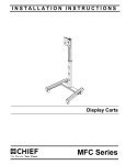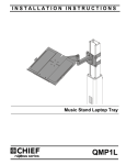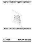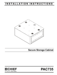
1
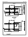
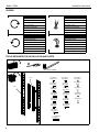
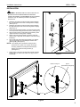
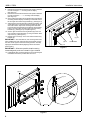
INSTALLATION INSTRUCTIONS
Universal Plasma Interface Bracket
Spanish Product Description
German Product Description
Portuguese Product Description
Italian Product Description
Dutch Product Description
French Product Description
MSBU / PSBU
MSBU / PSBU
Installation Instructions
DISCLAIMER
Milestone AV Technologies, and its affiliated corporations and
subsidiaries (collectively, "Milestone"), intend to make this
manual accurate and complete. However, Milestone makes no
claim that the information contained herein covers all details,
conditions or variations, nor does it provide for every possible
contingency in connection with the installation or use of this
product. The information contained in this document is subject
to change without notice or obligation of any kind. Milestone
makes no representation of warranty, expressed or implied,
regarding the information contained herein. Milestone assumes
no responsibility for accuracy, completeness or sufficiency of
the information contained in this document.
®Chief is a registered trademark of Milestone AV Technologies.
All rights reserved.
WARNING: Failure to read, thoroughly understand, and
follow all instructions can result in serious personal injury,
damage to equipment, or voiding of factory warranty! It is the
installer’s responsibility to make sure all components are
properly assembled and installed using the instructions
provided.
WARNING: Failure to provide adequate structural strength
for this component can result in serious personal injury or
damage to equipment! It is the installer’s responsibility to
make sure the structure to which this component is attached
can support five times the combined weight of all equipment.
Reinforce the structure as required before installing the
component.
WARNING: Exceeding the weight capacity of the Listed
IMPORTANT WARNINGS AND
CAUTIONS!
mount can result in serious personal injury or damage to
equipment! The MSBU/PSBU is used with several Listed flat
panel mounts that have maximum weight ratings from 125 lb
(56.7 kg) for the MSBU to 200 lb (90.7 kg) for the PSBU.
NOTE: The Listed Mount installation instructions will identify
WARNING: A WARNING alerts you to the possibility of
serious injury or death if you do not follow the instructions.
CAUTION: A CAUTION alerts you to the possibility of
damage or destruction of equipment if you do not follow the
corresponding instructions.
2
Model MSBU or PSBU interface brackets, and will
specify the weight rating of the mount.
Installation Instructions
MSBU / PSBU
MSB-U
PSB-U
3
MSBU / PSBU
Installation Instructions
LEGEND
Tighten Fastener
Phillips Screwdriver
Apretar elemento de fijación
Destornillador Phillips
Befestigungsteil festziehen
Kreuzschlitzschraubendreher
Apertar fixador
Chave de fendas Phillips
Serrare il fissaggio
Cacciavite a stella
Bevestiging vastdraaien
Kruiskopschroevendraaier
Serrez les fixations
Tournevis à pointe cruciforme
Loosen Fastener
Hex-Head Wrench
Aflojar elemento de fijación
Llave de cabeza hexagonal
Befestigungsteil lösen
Sechskantschlüssel
Desapertar fixador
Chave de cabeça sextavada
Allentare il fissaggio
Chiave esagonale
Bevestiging losdraaien
Zeskantsleutel
Desserrez les fixations
Clé à tête hexagonale
TOOLS REQUIRED FOR INSTALLATION AND PARTS
1/8" (provided)
T (2)
A (8) (Bag A)
#10-24 x 1/2"
H (8) (Bag H)
M5 x 16mm
N (8) (Bag N)
.750" x .250"
B (6) (Bag B)
M8 x 16mm
I (8) Bag I)
M5 x 25mm
O(8) (Bag O)
20mm
S (2)
J (8) Bag J)
M5 x 40mm
P(8) (Bag P)
#10
D (6) (Bag D)
M8 x 35mm
K (8) (Bag K)
M4 x 16mm
Q(8) (Bag P)
.318" x .078"
E (8) (Bag E)
M6 x 16mm
L (8) (Bag L)
M4 x 25mm
R(8) (Bag P)
.250"
F (8) (Bag F)
M6 x 20mm
M (8) (Bag M)
M4 x 40mm
C (6) (Bag C)
M8 x 20mm
G (8) (Bag G)
M6 x 35mm
S (4) (Bag Q)
M8 x 60mm
4
Installation Instructions
MSBU / PSBU
INSTALLATION
WARNING: IMPROPER INSTALLATION CAN LEAD TO
(T) x 2
MOUNT FALLING CAUSING SERIOUS PERSONAL
INJURY OR DAMAGE TO EQUIPMENT! DO NOT substitute
hardware. Only use hardware provided or specified by
manufacturer.
1.
2.
3.
4.
5.
6.
Mounting holes
Determine and mark the vertical center position between
the Left side Upper and Lower mounting holes in display.
(See Figure 1)
Determine and mark the vertical center position between
the Right side Upper and Lower mounting holes in display.
(See Figure 1)
Orient vertical mounting bracket (T) so that mounting holes
are on top and mounting slots are on bottom. (See Figure 1)
Align mounting holes in vertical mounting bracket (T) with
upper and lower mounting holes in display.
Adjust vertical mounting bracket (T) position until mark
made in step 1 aligns with center mark in vertical mounting
bracket (T).
Secure Left side vertical mounting bracket (T) to display
using two flat washer (R), and Phillips pan head screws
(B through M). (See Figure 2)
1
4
NOTE: If the display has a recessed mounting surface,
protrusions or a power box, a spacer and longer
mounting hardware must be placed between the
display and vertical mounting bracket (T).
(See Figure 2)
7.
Mounting Slots
Repeat steps 3 through 6 for Right side vertical mounting
bracket using the same hole locations to align brackets
horizontally.
Figure 1
(N,O,P, or Q)) x 4
(R) x 4
(used with E through M)
4
3
(B through M)
x4
(T) x 2
Figure 2
5
MSBU / PSBU
Installation Instructions
8.
Determine and mark the horizontal center position between
the Left and Right TOP mounting holes in display.
(See Figure 3)
9. Determine and mark the horizontal center position between
the Left and Right BOTTOM mounting holes in display.
(See Figure 3)
10. Orient upper horizontal mounting bracket (S) so that flanges
are facing towards display and resting in recessed area of
left and right vertical mounting brackets (T). (See Figure 1)
11. Adjust Upper horizontal mounting bracket (S) position until
center diamond in horizontal mounting bracket (S) aligns
with mark made in step 8 and mounting holes and slots
horizontal mounting bracket (S) are aligned with threaded
holes in mounting tabs of left and right vertical mounting
brackets (T). (See Figure 3) and (See Figure 4)
12. Secure upper horizontal mounting bracket (S) to left and
right vertical mounting brackets (T) using four Button head
cap screws (A). (See Figure 4)
13. Repeat steps 10 through 12 for lower horizontal mounting
bracket (S).
IMPORTANT ! : The orientation of, and mounting holes used,
when installing the lower horizontal mounting bracket must be
the same as the upper horizontal mounting bracket. Vertically
align upper and lower brackets by aligning holes or end of slots.
(See Figure 4)
1
4
(T) x 2
(S) x 2
(T) x 2
Figure 3
IMPORTANT ! : Whenever possible install mounting
screws diagonally as shown in detail in figure 4 below.
14. Install display with universal interface to mount following the
installation instructions provided with the mount.
(T) x 2
(T) x 2
4
3
(A) x 8
(S) x 2
Figure 4
6
Center Mark
Installation Instructions
MSBU / PSBU
7
MSBU / PSBU
Installation Instructions
USA/International
Europe
Chief Manufacturing, a products division
of Milestone AV Technologies
8805-000217 RevB
2009 Milestone AV Technologies, a
Duchossois Group Company
www.chiefmfg.com
11/09
Asia Pacific
A
P
F
A
P
F
A
8401 Eagle Creek Parkway, Savage, MN 55378
800.582.6480 / 952.894.6280
877.894.6918 / 952.894.6918
Fellenoord 130 5611 ZB EINDHOVEN, The Netherlands
+31 (0)40 2668620
+31 (0)40 2668615
Office No. 1 on 12/F, Shatin Galleria
18-24 Shan Mei Street
Fotan, Shatin, Hong Kong
P 852 2145 4099
F 852 2145 4477