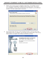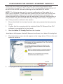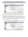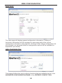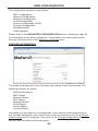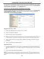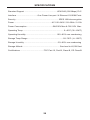
1
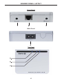
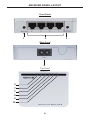
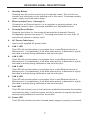
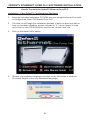
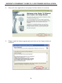
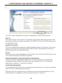
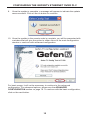
Ethernet Over PLC
GTV-ETH-2-PLC
User Manual
www.gefentv.com
ASKING FOR ASSISTANCE
Technical Support:
Telephone
(818) 772-9100
(800) 545-6900
Fax
(818) 772-9120
Technical Support Hours:
8:00 AM to 5:00 PM Monday thru Friday PST
Write To:
Gefen Inc.
c/o Customer Service
20600 Nordhoff St
Chatsworth, CA 91311
www.gefentv.com
[email protected]
Notice
Gefen Inc. reserves the right to make changes in the hardware, packaging and
any accompanying documentation without prior written notice.
GefenTV Ethernet Over PLC is a trademark of Gefen Inc.
© 2009 Gefen Inc., All Rights Reserved
All trademarks are the property of their respective companies
Rev X3
CONTENTS
1
Introduction
2
Operation Notes
3
Features
4
Sender Panel Layout
5
Sender Panel Descriptions
6
Receiver Panel Layout
7
Receiver Panel Descriptions
8
GefenTV Ethernet Over PLC Software Installation
11 Connecting The GefenTV Ethernet Over PLC
17 Automatic Security Setup Feature
19 Advanced Configuration
24 Web Configuration
27 Firmware Update Procedure
28 Specifications
29 Warranty
INTRODUCTION
Congratulations on your purchase of the GefenTV Ethernet Over PLC. Your
complete satisfaction is very important to us.
Gefen TV
Gefen TV is a unique product line catering to the growing needs for innovative
home theater solutions. We specialize in total integration for your home theater,
while also focusing on going above and beyond customer expectations to ensure
you get the most from your hardware. We invite you to explore our distinct
product line and hope you find your solutions. Don’t see what you are looking for
here? Please call us so we can better assist you with your particular needs.
The Gefen Ethernet Over PLC
Send RJ-45 Ethernet signals over power lines in the walls of your home with the
GefenTV Ethernet Over Power Line Bridge. The Bridge’s sender and receiver
units send Ethernet through the walls of a building at a distance of up to 1000
feet.
Ideal for tough installations where running CAT5/CAT6 cable is not possible,
these devices breathe new life into remote network extensions.
How It Works
Connect your Ethernet network cables to the GefenTV Ethernet Over Power Line
Bridge Sender unit, then plug the Bridge’s Sender into a nearby power outlet.
At the desired reception area in another room, plug the Bridge’s Receiver into
a power outlet. Power cycle your equipment and you will now receive network
signals at your remote destination as if you had cabled the run with Ethernet
cables.
1
OPERATION NOTES
READ THESE NOTES BEFORE INSTALLING OR
OPERATING THE GEFENTV ETHERNET OVER PLC
•
This device passes all 10/100BASE-T Ethernet network protocols (TCP/
IP, NETBUEI, Microsoft Networking, etc.) at speeds of up to 200Mbps (Full
duplex fast Ethernet).
•
All devices connected to the sending and receiving nodes must be on the
same power phase to communicate properly.
•
Multiple receiving nodes can be used on the same in-house power line
system to extend the network to multiple locations.
•
Performance of GefenTV Ethernet Over PLC can be affected by “noisy”
devices on the power lines. This can be alleviated by using a PLC filter
(Part# GTV-PLC-FUS for US and GTV-PLC-FEU for Europe). Offending
devices need to be connected to the PLC filter before being connected to the
wall outlet.
2
FEATURES
Features
•
Supports up to 200 Mbps data transmission rate
•
Extension of up to 200 feet (60 meters)
•
Web configuration for easy maintenance
•
Features include IGMP multicast, VLAN, and QOS packet management
•
3DES 168 bits encryption used for secure operation
•
Four RJ-45 Ethernet ports
Package Includes
(1) GefenTV Ethernet Over PLC sender
(1) GefenTV Ethernet Over PLC receiver
(1) 3 foot Ethernet Patch Cable
(2) Power Adapter Cables
3
SENDER PANEL LAYOUT
Front Panel
1
2
3
Back Panel
4
Top
p Panel
5
6
7
4
SENDER PANEL DESCRIPTIONS
1.
Standby Button
Pressing this will put the sending unit in standby mode. The unit will not
transfer any information to the receiving unit in this mode. To release
standby mode, simply press the button again.
2.
Ethernet Input Port
Connects to the Ethernet source (i.e a router, computer, or Internet
connection) via a standard network cable.
3.
Security/Reset Button
Pressing this button for 2 seconds will activate the Automatic Security
Configuration (please see page 17). Pressing this button for more than 10
seconds will perform a factory reset.
4.
AC Power Cable Input
Input for the supplied AC power cable.
5.
LAN LED
This LED will activate when a connection to a valid Ethernet source is
established. It will blink when activity is detected to signify that data is
actively being trafficked to and from the receiver.
6.
Link LED
This LED will activate once a link has been established between the sending
and receiving units. It will blink when activity is detected to signify that data is
actively being trafficked.
7.
Power LED
This LED will activate once the included power supply is properly connected.
5
RECEIVER PANEL LAYOUT
Front Panel
1
2
Back Panel
4
Top
p Panel
5
7
7
8
9
10
6
3
RECEIVER PANEL DESCRIPTIONS
1.
Standby Button
Pressing this will put the receiving unit in standby mode. The unit will not
transfer any information to the sending unit in this mode. To release standby
mode, simply press the button again.
2.
Ethernet Input Port ( 1 through 4)
Connects to an Ethernet device (i.e a computer or gaming system) via a
standard network cable. 4 ports are available for 4 separate devices.
3.
Security/Reset Button
Pressing this button for 2 seconds will activate the Automatic Security
Configuration (please see page 17). Pressing this button for more than 10
seconds will perform a factory reset.
4.
AC Power Cable Input
Input for the supplied AC power cable.
5.
LAN 1 LED
This LED will activate when a connection from a valid Ethernet device to
Ethernet port 1 is established. It will blink when activity is detected to signify
that data is actively being trafficked to and from this port.
6.
LAN 2 LED
This LED will activate when a connection from a valid Ethernet device to
Ethernet port 2 is established. It will blink when activity is detected to signify
that data is actively being trafficked to and from this port.
7.
LAN 3 LED
This LED will activate when a connection from a valid Ethernet device to
Ethernet port 3 is established. It will blink when activity is detected to signify
that data is actively being trafficked to and from this port.
8.
LAN 4 LED
This LED will activate when a connection from a valid Ethernet device to
Ethernet port 4 is established. It will blink when activity is detected to signify
that data is actively being trafficked to and from this port.
9.
Link LED
This LED will activate once a link has been established between the sending
and receiving units. It will blink when activity is detected to signify that data is
actively being trafficked to and from the sender.
10. Power LED
This LED will activate once the included power supply is properly connected.
7
GEFENTV ETHERNET OVER PLC SOFTWARE INSTALLATION
How to Connect the GefenTV Ethernet Over PLC
Installation of the GefenTV Configuration Assistant
1.
Insert the included installation CD-ROM into your computer that will be used
to configure the GefenTV Ethernet Over PLC.
2.
The auto run will begin the installation process. If auto run does not start or
auto run has been disabled, please navigate to “X:\” drive (where X is the
drive letter or your CD-ROM drive) and run the “autorun.exe” file.
3.
Click on the Install Utility option.
4.
Choose your preferred language and click on the OK button to continue.
(Currently English is the only selectable language)
8
GEFENTV ETHERNET OVER PLC SOFTWARE INSTALLATION
5.
Close all other applications and press the Next button to continue.
6.
Please read the license agreement and click on the I Agree button to
continue.
9
GEFENTV ETHERNET OVER PLC SOFTWARE INSTALLATION
7.
Please choose the program installation destination. The default location
is “C:\ Program Files\Gefen TV Ethernet Over Power Line”. To set your
own destination, click on the browse button and navigate to your preferred
location. Click the install button to continue.
8.
The program files will copy to the specified location in the previous step.
When the process is complete, you will see the window below. Click on the
finish button to complete the software installation process.
10
CONNECTING THE GEFENTV ETHERNET OVER PLC
1.
Connect the source (i.e. computer, router, switch) to the GefenTV Ethernet
Over PLC sender unit using the supplied CAT-5e cable.
2.
Connect the Ethernet devices (i.e. computer, game system, set-top box)
to the GefenTV Ethernet Over PLC receiver unit. Up to four devices are
supported.
3.
Connect the included power cables to both the GefenTV Ethernet Over PLC
sending and receiving units. Please ensure that the sender and receiver
units are connected to the same power line system on the same phase.
POWER LED: Once the power cable is connected, the Power LED should
become active with a solid blue color.
LAN LED: When a valid Ethernet connection is detected on the sending and
receiving Ethernet jacks, their corresponding LED’s will become active and
should emit a solid blue color.
LINK LED: The Link LED should be flashing red on initial boot up. Once a link
between the sending and receiving units has been established, it will emit a solid
blue color on both units.
IMPORTANT: The Link LED must be emitting a sold blue color before
configuration can continue. If this LED continues to flash red on both the sending
and receiving units, it is possible that they are not on the same phase. Please
confirm that both the sending and receiving units are attached to the same phase
by trying the unit on another power outlet.
11
CONFIGURING THE GEFENTV ETHERNET OVER PLC
Once both the sending and receiving units are linked and powered, basic
configuration can proceed. This section of the manual refers to the sending unit
as the LOCAL NODE, and the receiving unit as the REMOTE NODE.
NOTE: The following steps are for manual configuration of the nodes for a
basic secure network. These steps are optional, as the nodes will function with
their default settings. However, for security and performance purposes, it is
recommended that the following steps be performed. Automatic configuration is
also possible using the Automatic Security Configuration feature on page 17 in
lieu of the procedure outlined in this section.
1.
Ensure that both the local and remote nodes are powered and are properly
linked.
2.
Confirm that the computer with the installed GefenTV Ethernet Over PLC
software is connected to the local node.
3.
Start the Gefen TV Config Tool from this location:
Start Menu \ All Programs \ GefenTV Ethernet Over Power Line \ Gefen TV Config Tool
4.
The introduction screen should appear as the image below. Click on the next
button to continue.
5.
The program will begin to search for all connected nodes.
12
CONFIGURING THE GEFENTV ETHERNET OVER PLC
6.
Once all possible nodes have been detected, the program will display all of
these nodes as in the window below.
The local node that the computer is connected to will appear as the “ETH
connected node”. All remote nodes will be listed as “PLC connected nodes”.
NOTE: Both the local and remote nodes must use the same Net ID and
encryption passwords for proper operation. These will be configured in the next
step. However, it is important to configure the remote nodes first. If the local node
is configured first, all remote nodes will become inaccessible and will have to be
removed from their locations and physically connected to the computer, where
they can be configured to match the local node’s settings.
7.
To begin configuration, click on the mac address of the remote node (PLC
connected node) and then click on the next button.
13
CONFIGURING THE GEFENTV ETHERNET OVER PLC
8.
The PLC node configuration screen is separated into the following items:
NET ID
This is the name of the network. This name must be the same for both the local
and remote nodes for proper operation. The NET ID can be an ASCII string up to
20 characters long.
ENCRYPTION KEY
This is the password needed for network authentication by all nodes. If you wish
to set an encryption key, please set the NET ID first. The password can be an
ASCII string up to 24 characters long.
ALIAS
This name is for easy identification of the node. This can be an ASCII string of up
to 10 characters long. This field is optional.
NEW PASSWORD (CONFIGURATION PASSWORD)
This is to set the configuration password. If a new password is set here, the
configuration tool will ask for it every time you access the node. The default
password is “paterna”. This field is optional.
CONFIRM PASSWORD
The password entered into the new password listing above must also be entered
here. This is for confirmation purposes.
Enter the Net ID, encryption key, and alias into the corresponding fields. Once
these fields are completed, click on the next button to continue.
14
CONFIGURING THE GEFENTV ETHERNET OVER PLC
9.
Once the update is complete, a message will appear to indicate the update
was successful. Click on the ok button to continue.
10. Once the update to the remote node is complete, you will be presented with
a window that will give the option to either return to the main configuration
window or continue with advanced configuration.
For basic usage, it will not be necessary to continue to the advanced
configuration. For advanced options, please see the ADVANCED
CONFIGURATION section on page 19. To continue with the basic configuration,
click on the next button.
15
CONFIGURING THE GEFENTV ETHERNET OVER PLC
11. Once the configuration for the remote node is complete, the local node will
then have to be configured. Click on the local node which is labeled as the
“ETH connected node” and press next to continue.
12. Using the same Net ID and encryption key from the remote node, input
the same information into the corresponding fields for the local node. The
Alias field should be set to a different name as the remote node for easy
identification.
Once the information has been input, click on the next button to continue. A
confirmation window will appear once the update is complete. The same window
in step 10 will appear with the option to continue with the advanced configuration.
It is not necessary to continue with the advanced configuration for basic
operation. Click on the next button to return to the main configuration window and
exit the configuration tool by clicking on the exit button.
16
AUTOMATIC SECURITY CONFIGURATION FEATURE
To quickly setup the Gefen TV Ethernet Over PLC for secure use, the Automatic
Security Configuration Mode (ASCM) can be activated on each node. Follow the
below steps to automatically setup a secure connection between multiple nodes.
It is important to understand these concepts before proceeding with the
Automatic Security Configuration.
•
Master Node (Fixed Access Point) - The Master node is the unit that all of
the Slave nodes use to copy the Net ID and Encryption Key from. Because
all of the nodes on a network need to have the same Net ID and encryption
key to operate properly together, there needs to be a single Master node
that stores the information that all other Slave nodes will use to properly
configure themselves. A Master node is indicated by its Power LED glowing
a solid RED color. It is recommended to have only one Master node on the
PLC network.
•
Slave Node (Normal) - A node in this mode will be indicated by its Power
LED glowing a solid Blue color. Multiple Slave nodes can be on the same
PLC network.
•
Automatic Security Configuration Mode (ASCM) - This mode is initialized
by pressing and holding the Security/Reset button on the front panel for
approximately 2 seconds. Once the node’s Power LED begins flashing RED,
release the button. This mode lasts for approximately 30 seconds and will
return to normal operation after this time period.
•
Both the Master and Slave nodes must be in ASCM for the automatic
procedure to complete successfully.
•
When a Slave node initializes ASCM, it will first attempt to find a Master
node in ASCM. If a Master node in ASCM is not found, it will assume the role
of the Master node. To avoid accidentally setting a Slave node as a Master
node, make sure that the Master node is in ASCM when activating a Slave’s
ASCM.
•
Any Slave node that assumes the role of a Master node will automatically
have a random ASCII Net ID and Encryption Key generated.
•
Connect the computer with the installed Gefen TV Config Tool software to
the node that you wish to initially set as the Master node.
•
If a node is connected to media server or router, it is recommended that this
node be set as the Master node for increased performance.
Please refer to the next page for step by step instructions on how to activate the
Automatic Security Configuration feature for the Gefen TV Ethernet Over PLC
nodes.
17
AUTOMATIC SECURITY CONFIGURATION FEATURE
1.
Connect the computer with the installed Gefen TV software to the node you
wish to set as the Master node.
2.
Press and hold the Security/Reset button on the node (ASCM), located on
the front panel, for approximately 2 seconds. The Power LED should begin
to flash RED, then release the button.
3.
After approximately 30 seconds, the Power LED should stop flashing and
glow solid RED. This indicates that it is now a Master node. If this node was
a Slave node (normal node) before this process, it will now have a randomly
generated ASCII Net ID and Encryption Key set.
4.
Open the Gefen TV Config Tool (page 12). There should be a random
ASCII value as the Net ID. If you wish to use this Net ID for the other Slave
nodes, proceed to step 5. Otherwise, you can now set your own Net ID and
encryption password which will be applied to all of the Slave nodes in the
next step. To do this, click on the local “ETH connected node” MAC address
and press the next button. Change only the Net ID and encryption password
fields and click on the next button. Once the local node has been updated,
proceed to step 5.
5.
For this step to complete successfully, both the Master and Slave nodes
have to be in ASCM. To do this, press and hold the Security/Reset button on
the Master node for approximately 2 seconds. The Power LED should begin
flashing RED. Within 30 seconds, press and hold the Security/Reset button
on the Slave node(s) for 2 seconds to enter ASCM. The Slave node’s Power
LED should also begin to flash while it receives the Net ID and Encryption
Key information from the Master node. Once the Power LED on both the
Master and Slave nodes stop flashing and glow solid, the setup will be
complete. Check this by opening the Gefen TV Config Tool and seeing that
all nodes have the same Net ID.
NOTE: If the Slave nodes are located at a great distance from the Master node,
it is recommended that Step 5 be repeated for each Slave node separately.
The window that each device remains in ASCM is only 30 seconds, and it may
not be possible to put all Slave nodes in the ASCM within the time frame. It is
also possible to temporarily relocate the Slave nodes to a PLC port closer to
the Master node for this configuration process, and then move them to their
permanent location after this process is complete. If a Slave node is accidentally
set as a Master node, you can hard reset the node by pressing and holding the
Security/Reset button for approximately 10 seconds. This will revert the node to a
Slave node and reset all internal configurations to factory settings.
18
ADVANCED CONFIGURATION
There are optional advanced settings that can be configured for each node. The
advanced menu can be accessed directly through the main configuration page.
Click on the MAC address of the node you wish to configure and click on the
advanced button to the left of the node listing.
GENERAL
Hardware Reset
This will reboot the node. Settings made in this menu will be applied once the
node is restarted.
Factory Reset
This will return the node to factory default settings. A password is required to
complete this operation. The default password is “betera”.
19
ADVANCED CONFIGURATION
Firmware Update
This section is used to update the node’s firmware from a server location. Please
see the Firmware Update section on page 27 for full details.
Upgrade Firmware
This section is used to update the node’s firmware from a file. Please see the
Firmware Update section on page 27 for full details.
NETWORK
IP Configuration
For access to the node’s web configuration tool an IP address must be assigned.
Options are:
Fixed - Manually assigned IP address
DHCP - IP assigned by the networks DHCP server
Fixed IP Configuration
Assign an IP address, subnet mask, and default gateway for web tool access.
Click on the update button to apply settings made in this tab.
20
ADVANCED CONFIGURATION
MULTICAST
IGMP Multicast
This option will enable or disable the node’s ability to transmit IGMP multicast
data.
SECURITY
The security tab will allow the user to adjust the configuration password, the
encryption password, the network ID, and the alias for the node. For a detailed
description of each of these options, please see page 14.
21
ADVANCED CONFIGURATION
VLAN
This option will enable or disable the node’s ability to accept VLAN data. If this
feature is enabled on one of the nodes, it must be set on all other for VLAN tag
packets to pass.
QOS
QOS (quality of service) is supported for managing traffic between nodes. The
supported protocols are:
1.
2.
3.
4.
5.
6.
TCP port priority
UDP port priority
802.1p
TOS (RFC 1122)
DSCP (RFC 2475)
No Priority
22
ADVANCED CONFIGURATION
ADVANCED QOS
QOS (quality of service) prioritization. Rule 1 will be applied to all packets first
and then Rule 2. Prioritization protocols are:
1.
2.
3.
4.
5.
6.
7.
8.
UDP is high priority, TCP is low priority
TCP is high priority, UDP is low priority
UDP port XXXX is high priority, the rest is low priority
UDP port XXXX is low priority, the rest is high priority
TCP port XXXX is high priority, the rest is low priority
TCP port XXXX is low priority, the rest is high priority
Use 802.1p prioritization
No prioritization
23
WEB CONFIGURATION
If an IP address has been set in the ADVANCE CONFIGURATION PANEL,
access to the WEB UTILITY will be enabled. To access the WEB UTILITY, open
your web browser and type the ip address into the address field. The IP address
is dependant on the IP Configuration Setting assigned on page 20. The IP
address can either be assigned by the DHCP server or a static IP address can be
manually assigned.
AUTHENTICATION
The browser should open the authentication page displayed below.
Authentication
To enter the WEB UTILITY, enter the configuration password. The default
password is “paterna” unless modified during the setup stage on page 14.
Factory Reset
The unit can be reset to factory settings from this menu. Enter the factory reset
password. The default password is “betera”.
24
WEB CONFIGURATION
MAIN PAGE
The main page will display general configuration information. Clicking on
the further information link will navigate to a new page with all the current
configuration information (see page 26). Clicking on the change configuration link
will navigate to a new page where all configuration options will be available for
adjustment (see below).
WEB CONFIGURATION
This page will allow the user to adjust all options that are available just as in the
ADVANCED CONFIGURATION PANEL in the GEFENTV CONFIG TOOL.
25
WEB CONFIGURATION
The configuration options are as follows:
MAC Configuration
Network Configuration
Multicast Configuration
VLAN Configuration
Priority Configuration (QOS)
Security Configuration
Hardware Reset
Flash Upgrade
Please refer to the ADVANCED CONFIGURATION section, starting on page 19,
for information on the above categories. Going back to the main page can be
done by clicking on any of the Return to main page links.
FURTHER INFORMATION
This page will display all of the information and status of the current node. The
following sections are listed:
System Information
MAC Status
Network Status
PHY Status
Multicast Status
VLAN Status
Priority Status
Security Status
Information on this page is not configurable. If you wish to make adjustments to
any of these categories, return to the main menu by clicking on any of the Return
to main page links on the page. Then click on the Change configuration link
which is also available on the main page.
26
FIRMWARE UPDATE PROCEDURE
The firmware for the GefenTV Ethernet Over PLC can be updated by FTP, TFTP,
or a direct file. The firmware update can be executed from either the ADVANCED
CONFIGURATION PANEL, or the WEB UTILITY.
UPDATE VIA THE ADVANCED CONFIGURATION PANEL
Firmware updates can be accomplished from the General tab in the ADVANCED
CONFIGURATION PANEL. See page 19 for instructions on how to enter the
ADVANCED CONFIGURATION PANEL.
Upgrade Via FTP or TFTP
1.
Select the update protocol. Either FTP or TFTP
2.
Enter the server IP address
3.
Enter the user name and password
4.
Enter the name of the file (if the file is not in the root directory of the TFTP or
FTP directory, you have to write the whole route from root server directory)
5.
Select which section you would like to update (Firmware, Loader or Factory
Settings)
6.
Click on the firmware update button
Upgrade Via File
1.
Use the browse button to the right of the firmware file window and select the
firmware update file. You can also manually type the full path to the firmware
file
2.
Click on the upgrade firmware button
NOTE: This procedure is the same using the web utility. The web update section
is located in the change configuration settings, which is accessible from the main
page.
27
SPECIFICATIONS
Standard Support ........................................................ UPA DHS (200 Mbps) PLC
Interface .................................... One Power Line port / 4 Ethernet 10/100M Ports
Security .......................................................................... 3DES 168 bits encryption
Power ................................................................. AC 100~240V / 50~60Hz / 0.15A
Power Consumption .............................................8W/230V Max & 7W/110V Max
Operating Temp ....................................................................... 0~40ºC (32~104ºF)
Operating Humidity ..................................................... 10%~90% non-condensing
Storage Temp Range ............................................................ -20~70ºC (-4~158ºF)
Storage Humidity .......................................................... 5%~95% non-condensing
Storage Altitude ................................................................ Sea level to 40,000 feet
Certifications ........................................ FCC Part 15, Part B, Class B, CE Class B
28
WARRANTY
Gefen warrants the equipment it manufactures to be free from defects in material
and workmanship.
If equipment fails because of such defects and Gefen is notified within two (2)
years from the date of shipment, Gefen will, at its option, repair or replace the
equipment, provided that the equipment has not been subjected to mechanical,
electrical, or other abuse or modifications. Equipment that fails under conditions
other than those covered will be repaired at the current price of parts and labor in
effect at the time of repair. Such repairs are warranted for ninety (90) days from
the day of reshipment to the Buyer.
This warranty is in lieu of all other warranties expressed or implied, including
without limitation, any implied warranty or merchantability or fitness for any
particular purpose, all of which are expressly disclaimed.
1.
Proof of sale may be required in order to claim warranty.
2.
Customers outside the US are responsible for shipping charges to and from
Gefen.
3.
Copper cables are limited to a 30 day warranty and cables must be in their
original condition.
The information in this manual has been carefully checked and is believed to
be accurate. However, Gefen assumes no responsibility for any inaccuracies
that may be contained in this manual. In no event will Gefen be liable for
direct, indirect, special, incidental, or consequential damages resulting from
any defect or omission in this manual, even if advised of the possibility of such
damages. The technical information contained herein regarding the features and
specifications is subject to change without notice.
For the latest warranty coverage information, please visit Gefen’s Warranty web
page at http://www.gefen.com/kvm/aboutus/warranty.jsp
PRODUCT REGISTRATION
Please register your product online by visiting Gefen’s web site at
http://www.gefen.com/kvm/Registry/Registration.jsp
29
Rev X3
20600 Nordhoff St., Chatsworth CA 91311
1-800-545-6900
818-772-9100
www.gefentv.com
fax: 818-772-9120
[email protected]