Transcript
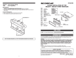
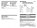
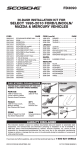
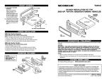
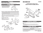
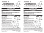
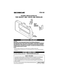
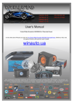
FD1300
DIN / SHAFT RADIO INST
ALLA
TION
INSTALLA
ALLATION
1. Insert the FD1300 pocket into the lower half of the radio opening and push the locking tabs in as far as
possible to lock the pocket in place. (Make sure they push in until flush)
DIN RADIO:
1995-UP FORD/MAZDA DOUBLE-DIN
RADIO REPLACEMENT POCKET KIT
A. Slide radio's mounting sleeve (if applicable) into the dash opening and bend outward all available
mounting tabs.
SHAFT RADIO:
NOTE: When installing a shaft radio, a DIN-to-Shaft adaptor is recommended for proper installation. This is
included with the FD1300 Kit or available separately as Scosche DIN-1190.
B. Install the radio and kit into the upper dash opening using metal spring clip or plastic locking clips.
(See DIN-1190 instructions).
ILLUSTRATION A:
RADIO'S
REAR SUPPORT
STRAP
RADIO
FD1300 POCKET KIT
DIN RADIO
1995-UP FORD EXPLORER
ILLUSTRATION B:
FD1300 POCKET AND
SHAFT RADIO KIT
POCKET
SHAFT
RADIO
SCOSCHE
DIN1190 KIT
REAR
SUPPORT
(SEE ILLO)
REAR
SUPPORT
BRACKET
REAR SUPPORT
SLIDE LOCATED
IN VEHICLE
REAR SUPPORT
(SEE ILLO)
FD1300
POCKET KIT
REAR SUPPORT IS VITAL TO THE INTEGRITY OF INSTALLATION
VEHICLE APPLICATIONS:
FACTOR
Y WIRE CODES
ACTORY
1986-UP FORD, LINCOLN, MERCURY VEHICLES
NOTE: These codes are for use with non-premium/JBL equipped vehicles. If your vehicle is so equipped
please call SCOSCHE at (800) 621-3695 for additional accessory/wiring options.
(Vehicles equipped with "standard," large-type connectors)
BLACK SPEAKER:
GRAY - POWER/SPEAKER:
A
B
C
D
E
F
G
=
=
=
=
=
=
=
H
=
+12V Constant, Battery
Empty
+12V Ignition
Illumination
LCD
Ground
Remote Turn On
(Factory Amplifier)
Empty
A
A
B
B
C
C
D
D
E
E
F
F
G
G
H
H
A
B
C
D
E
F
G
H
=
=
=
=
=
=
=
=
Left Front Positive
Left Front Negative
Left Rear Positive
Left Rear Negative
Right Front Positive
Right Front Negative
Right Rear Positive
Right Rear Negative
FORD:
1995-UP
1997-UP
1995-UP
1995-UP
1999-UP
Crown Victoria
Econoline Van
Explorer 2DR/4DR
Ranger Pickup
F-250/350 Super Duty
LINCOLN:
1995-97 Continental
1995-UP Mark VIII
1995-97 Town Car *
MAZDA:
1995-UP B Series pickup
MERCURY:
1995-UP Grand Marquis
1996-UP Mountaineer
* Due to dash cavity limitations, the pocket should
be mounted above the stereo in this vehicle.
PRELIMINAR
Y/RADIO REMOV
AL
PRELIMINARY/RADIO
REMOVAL
CAUTION: Before proceeding with the instruction disconnect the negative battery cable to prevent any
possible electrical damage.
RADIO REMOVAL:
1988-UP FORD VEHICLES
1.
2.
3.
4.
5.
6.
7.
8.
9.
10.
11.
12.
Green/Orange = Right Front Negative (RF-).
White/Green = Right Front Positive (RF+).
Brown/Pink = Right Rear Negative (RR-).
Orange/Red = Right Rear Positive (RR+).
Empty.
Empty.
Black = Grounding Dimmer.
Light Blue/Red = Dimmer (+12V Variable).
Black/Green = Source Ground, -12V Amp/Chassis.
Light Blue/White = Left Front Negative (LF-).
Orange/Green = Left Front Positive (LF+).
TanYellow = Left Rear Negative (LR-).
13.
14.
15.
16.
Gray/Light Blue = Left Rear Positive (LR+).
Back/Green = 12V Chassis Ground.
Yellow/Black = +12V Accessory.
Light Green/Violet = +12V Constant.
1
3
2
9
10
5
4
11
12
6
13
14
15
3. Unplug connectors and remove radio.
LIABILITY DISCLAIMER
This instruction booklet is based on carefully documented data and research of automobile dash disassembly, wire harness/
codes and information pertaining to installation of this kit (#FD1300) in 1995-UP Ford/Mazda Vehicles. Scosche Industries,
Inc. can not be held responsible for discrepancies/inconsistencies that may occur due to the automobile manufacturing
changes or options, or damage that may occur in the automobile during the installation of components while using this
booklet.
8
7
1. Carefully insert Ford Din Radio removal tools into the holes at each side of the front of the radio.
2. Slightly pull the tools apart (away from each other) and the radio will slide out of the dash.
16
If you have any further questions, call:
©1998 SCOSCHE INDUSTRIES, INC.
TECH HELP
1-800-621-3695, ext. 3
SI 4/98-FD1300 (3000227)