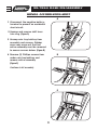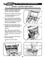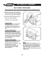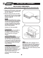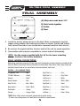
1
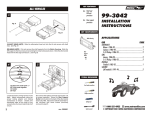
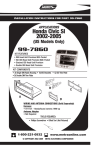
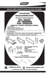
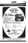
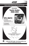
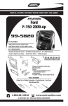
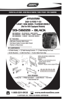
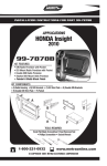
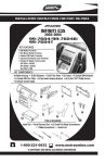
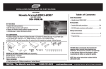
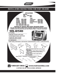
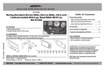
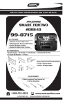
INSTALLATION INSTRUCTIONS FOR PART 99-7864
APPLICATIONS
Honda Accord
2003-2007
(Equipped with Single Zone Climate Controls)
99-7864
KIT FEATURES
• DIN Radio Provision
• ISO Radio Provision
KIT COMPONENTS
A) Radio/Climate Control Housing B) ISO Brackets C) ISO Trim Plate D) PPH-1034 Screws
B
A
C
D
WIRING AND ANTENNA CONNECTIONS (Sold Separately)
WIRING HARNESS:
• 70-1721 - Honda/Acura Harness 1998-up
• 70-78640Z - Accord Dual Zone Eliminator Harness 2003-07
ANTENNA ADAPTER:
Not Required
TOOLS REQUIRED:
Small Flat Blade Screwdriver/ • Panel Removal Tool
• Phillips Screwdriver
1-800-221-0932
www.metraonline.com
© COPYRIGHT 2004-2009 METRA ELECTRONICS CORPORATION
99-7864
TABLE OF CONTENTS
Dash Disassembly
- Honda Accord 2003-2007 . . . . . . . . . . . . . . . . . . . . . . . . . . . . . . . . . . . . . . 1, 2
Kit Assembly
- DIN Radio Provision . . . . . . . . . . . . . . . . . . . . . . . . . . . . . . . . . . . . . . . . . . . . . 3
- ISO Radio Provision . . . . . . . . . . . . . . . . . . . . . . . . . . . . . . . . . . . . . . . . . . . . . 4
Final Assembly . . . . . . . . . . . . . . . . . . . . . . . . . . . . . . . . . . . . . . . . . . 5
*Note:
Refer also to the instructions included with the aftermarket radio.
NOTE:
To adapt dual zone climate controls to a single zone system to work
with this kit you will need Metra harness #70-7864DZ (sold separately).
KNOWLEDGE IS POWER
Enhance your installation and fabrication skills by
enrolling in the most recognized and respected
mobile electronics school in our industry.
Log onto www.installerinstitute.com or call
800-354-6782 for more information and take steps
toward a better tomorrow.
99-7864 DASH DISASSEMBLY
HONDA ACCORD 2003-2007
A
1 Disconnect the negative batteryterminal to prevent an accidental
short circuit.
2 Unsnap and remove shift lever
trim ring. (Figure A)
R
N
D
D
3 Unsnap coin tray/ashtray from
assembly and remove. Rubber
cover may come out first but
entire assembly must be removed
to access screws below. (Figure B)
B
4 Remove (2) Phillips screws from
under coin tray/ashtray and
remove entire assembly.
(Figure C)
Continue to kit assembly.
R
N
D
D
C
R
N
D
D
1
99-7864 DASH DISASSEMBLY
HONDA ACCORD 2003-2007
*Note: Refer also to the instructions included with the aftermarket radio.
D
5 Remove (2) Phillips screws from
bottom of pocket assembly and
unsnap and remove. (Figure D)
6 Remove (2) Phillips screws facing
up under radio/climate control
assembly.) (Figure E)
7 Push and hold the hazard button
down. Carefully insert a flat blade
screwdriver into the slot below the
button and push down to release
the center clip. (Figure F)
P
D
8 Unsnap and remove upper panel
(including a/c vents) and remove (3)
Phillips screws behind the panel.
(Figure G)
E
Tip: You can use a hook tool to
grasp the panel inside of the vent
and pull toward the rear of the vehicle. Be careful not to scratch the
panel.
9 Unclip and remove radio/climate
control assembly.
Continue to kit assembly.
G
F
2
N
D
R
99-7864 KIT ASSEMBLY
DIN RADIO PROVISION
*Note: Refer also to the instructions included with the aftermarket radio.
A
1 Snap the DIN cage into the Radio
Housing and secure by bending the
metal locking tabs down. (Figure A)
2 Slide the aftermarket radio into the
cage and secure. (Figure B)
Continue to final assembly.
Programming:
In order to adjust the 99-7864 to
the different types of radios
available in the Honda Accord,
the 99-7864 has a program feature.
B
4 DOOR SEDAN ONLY:
To program the kit you will need
to start your vehicle then hold
the A/C button for approximately
5 seconds or until the light starts
to blink.The climate controls will
be programmed when the light
stops blinking.
2 DOOR COUPE ONLY:
To program the kit you will need
to start your vehicle then hold
the Rear Defrost button for
approximately 5 seconds or until
the light starts to blink.
The climate controls will be
programmed when the light
stops blinking.
Note:
The orange wire coming out of
the back of the 99-7864 needs to
be connected to the orange illumination wire coming from the
Metra 70-1721 wire harness (sold
separately).
3
99-7864 KIT ASSEMBLY
ISO RADIO PROVISION
*Note: Refer also to the instructions included with the aftermarket radio.
A
1 Mount the ISO Brackets to the head
unit with the screws supplied with
the unit. (Figure A)
2 Slide the head unit into the radio
opening until the side clips engage.
Snap the Trim plate into the Radio
Housing. (Figure B)
NOTE:
When reinstalling the screws
into the bottom of the 99-7864
use the (2) supplied Phillips
screws instead of the factory
screws removed in step 5 in
Dash Disassembly.
B
Continue to final assembly.
Programming:
In order to adjust the 99-7864 to
the different types of radios
available in the Honda Accord,
the 99-7864 has a program
feature.
4 DOOR SEDAN ONLY:
To program the kit you will need
to start your vehicle then hold
the A/C button for approximately
5 seconds or until the light starts
to blink.The climate controls will
be programmed when the light
stops blinking.
Note:
The orange wire coming out of
the back of the 99-7864 needs to
be connected to the orange illumination wire coming from the
Metra 70-1721 wire harness (sold
separately).
2 DOOR COUPE ONLY:
To program the kit you will need
to start your vehicle then hold
the Rear Defrost button for
approximately 5 seconds or until
the light starts to blink.The climate controls will be programmed when the light stops
blinking.
4
99-7864 FINAL ASSEMBLY
FINAL ASSEMBLY
A
(A) Strip wire ends back 1/2"
B
B) Twist ends together
C) Solder
D) Tape
C
D
1 Locate the factory wiring harness in the dash. Metra recommends using the
proper mating adapter and making connections as shown. (Isolate and individually tape off the ends of any unused wires to prevent electrical short circuit.)
2 Re-connect the negative battery terminal and test the unit for proper operation.
3 Reassemble radio and dash assemblies in reverse order of disassembly.
NOTE: Use the screws supplied with this kit for the lower mounting
screws instead of the factory hardware.
FINAL WIRING CONNECTIONS
Make wiring connections using the EIA color code chart shown below and the instructions included with the
head unit. Metra recommends making connections as shown below; Strip, Splice, Solder, Tape. Isolate and
individually tape off ends of any unused wires to prevent electrical short circuit.
METRA / EIA WIRING CODE
12V Ignition / Acc. . . . . . . . . . Red
Right Front (+) . . . . . . . . . . . . Gray
12V Batt / Memory. . . . . . . . . Yellow
Right Front (-). . . . . . . . . . . . . Gray/ Black
Ground. . . . . . . . . . . . . . . . . . Black*
Left Front (+) . . . . . . . . . . . . . White
Power Antenna. . . . . . . . . . . . Blue
Left Front (-). . . . . . . . . . . . . . White / Black
Amp Turn-On . . . . . . . . . . . . . Blue / White
Right Rear (+) . . . . . . . . . . . . Violet
Amp Ground. . . . . . . . . . . . . . Black / White
Right Rear (-) . . . . . . . . . . . . . Violet / Black
Illumination . . . . . . . . . . . . . . Orange
Left Rear (+) . . . . . . . . . . . . . Green
Dimmer . . . . . . . . . . . . . . . . . Orange / White
Left Rear (-) . . . . . . . . . . . . . . Green / Black
*NOTE: When a Black wire is not present, ground radio to vehicle chassis.
All colors may not be present on all leads due to manufacturer’s specifications.
5
99-7864 INSTRUCTIONS
1-800-221-0932
www.metraonline.com
REV. 05/04/09 © COPYRIGHT 2004-2009 METRA ELECTRONICS CORPORATION INST99-7864