1
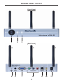
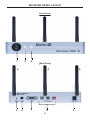
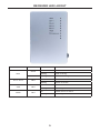
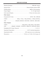
Wireless VGA Extender LR
GTV-WVGA-LR
User Manual
www.gefentv.com
ASKING FOR ASSISTANCE
Technical Support:
Telephone
(818) 772-9100
(800) 545-6900
Fax
(818) 772-9120
Technical Support Hours:
8:00 AM to 5:00 PM Monday thru Friday PST (Pacific Standard Time)
Write To:
Gefen Inc.
c/o Customer Service
20600 Nordhoff St
Chatsworth, CA 91311
www.gefen.com
[email protected]
Notice
Gefen Inc. reserves the right to make changes in the hardware, packaging and
any accompanying documentation without prior written notice.
Wireless VGA Extender LR is a trademark of Gefen Inc.
© 2009 Gefen Inc., All Rights Reserved
All trademarks are the property of their respective companies
Rev A5
CONTENTS
1
Introduction
2
Operation Notes
3
Features
4
Sender Panel Layout
5
Sender Panel Descriptions
6
Receiver Panel Layout
7
Receiver Panel Descriptions
8
Sender LED Layout
9
Receiver LED Layout
10 Connecting And Operating The Wireless VGA LR
12 Specifications
13 Warranty
INTRODUCTION
Congratulations on your purchase of the Wireless VGA LR. Your complete
satisfaction is very important to us.
Gefen
Gefen delivers innovative, progressive computer and electronics add-on solutions
that harness integration, extension, distribution and conversion technologies.
Gefen’s reliable, plug-and-play products supplement cross-platform computer
systems, professional audio/video environments and HDTV systems of all sizes
with hard-working solutions that are easy to implement and simple to operate.
The Gefen Wireless VGA LR
The Wireless VGA Extender LR allows a VGA display or projector to be
conveniently located up to 100 feet away from the source.
The Wireless VGA Extender LR features line-of-sight signal transmission and
through walls at resolutions of up to 1280x1024, using industry-proven 2.4GHz
802.11b/g/n Wireless network technology. The Extender can be operated on any
one of 4 channels to minimize interference.
How It Works
This product is a plug-and-play solution. No special configuration is necessary.
The Wireless VGA Extender LR system consists of a Sender and a Receiver.
The Sender is connected to the VGA source with a VGA cable. The Receiver
is connected to the display with a VGA cable. 12V external power supplies are
connected to the Sender and the Receiver.
Supported A/V input sources also include Component, S-Video and Composite
Video. A/V sources can be individually selected by pressing the Source Selector
button on the front panel of either the Sender unit or the Receiver unit. The
current wireless channel can be selected in the same way with the Channel
Selector button.
1
OPERATION NOTES
READ THESE NOTES BEFORE INSTALLING OR
OPERATING THE WIRELESS VGA LR
•
The Wireless VGA LR will accept component video signals (YPbPr) up
to 1080p. However, 1080i and 1080p signals will be down scaled and
transmitted at 1280x720. Please see the table at the bottom of this page for
a list of input and output resolutions and framerates.
•
For better transmitting quality, please do not place units into cabinets or
cupboards that will reduce the wireless transmitting signal. Also, please note
that only one set can be used at any given time at a location. Multiple sets in
close proximity may cause interference with each other.
•
The following input formats are accepted:
Composite: NTSC / PAL / SECAM: 480i@60Hz , 576i@50Hz
S-Video: NTSC / PAL / SECAM: 480i@60Hz , 576i@50Hz
Y/Pb/Pr: 480i/p@60Hz, 576i/p@50Hz, 720p@50/60Hz, 1080i/p@50/60Hz
VGA:
640X480@60Hz, 800X600@60Hz,1024X768@60Hz,
1280X768@60Hz, 1280X1024@60Hz
•
The following are the output formats:
Y/Pb/Pr:
VGA:
•
480p@60Hz, 576p@50Hz, 720p@60Hz,
640x480@@60Hz, 800X600@60Hz, 1024X768@60Hz,
1280X768@60Hz, 1280X1024@60Hz
The following are the transfer frame rates:
Composite : 480i@60Hz → 480i@60fps
576i@50Hz → 576i@50fps
S-Video :
480i@60Hz → 480i@60fps
576i@50Hz → 576i@50fps
Y/Pb/Pr :
480 i/p @60Hz →480i/p@60fps
576 i/p @50Hz →576i/p@50fps
720p@60Hz → 720p@30fps
720p@50Hz → 720p@25fps
1080i@60Hz → 720p@30fps
1080i@50Hz → 720p@25fps
1080p@60Hz → 720p@30fps
1080p@50Hz → 720p@25fps
VGA :
640X480@60Hz (4:3) → 640x480@30fps
800X600@60Hz (4:3) → 800X600@30fps
1024X768@60Hz (4:3) → 1024X768@30fps
1280X768@60Hz (5:3) → 1280X768@30fps
1280X1024@60Hz (5:4) → 1280X1024@20fps
2
FEATURES
Features
•
Wireless extension of VGA up to 100 feet
•
•
•
•
Video Input Formats Supported:
Max. VGA: 1280x1024@60Hz
Max. Y/Pb/Pr: 1080p@60Hz
SVideo, Composite: 480i@60Hz, 576i@50Hz
•
•
•
Video Output Formats Supported:
Max. VGA: 1280x1024@60Hz
Max. Y/Pb/Pr: 720p@60Hz
SVideo, Composite: 480i@60Hz, 576i@50Hz
•
•
Switch between four audio/video sources from the sender’s location
•
Plug-and-Play installation with no special configuration required
•
4 wireless channels for resistance to interference
•
L/R Analog Audio supported
Package Includes
(1) GTV-WVGA-LR Wireless VGA Sender
(1) GTV-WVGA-LR Wireless VGA Receiver
(2) 12V / 1A Power Supplies
(1) 6 foot VGA cable (M-M)
(1) User’s Manual
3
SENDER PANEL LAYOUT
Front Panel
2
1
3
Back Panel
4
5
4
6
7
8
4
4
9
10
11
SENDER PANEL DESCRIPTIONS
1
Power Switch
This switch will toggle the main power on and off.
2
Source Selector Button
This button will cycle through the available input video sources. The cycle is
outlined below:
VGA
Component
S-Video
Composite
3
Channel Selection Button
This button will cycle through the available radio channels. There are 4 channels
to choose from. This feature is useful when a certain channel is oversaturated
and another needs to be used. Changes made on this unit will automatically be
reflected on the opposite unit.
4
Transmission Antennas
These antennas will transmit the video/audio signals to the receiver unit.
5
Reset Button
These button will restore the units to factory defaults.
6
3.5mm Mini-Jack Audio Input
This input will accept a 3.5mm mini-jack for analog stereo audio transmission.
This input will accept a 3.5mm mini-jack audio device for analog audio. Audio
from this input will be transmitted to the receiver.
7
VGA Video Input
This input will accept a single VGA video source for transmission to the receiver
at the remote location.
8
Component Video Input
This input will accept a single Component video source for transmission to the
receiver at the remote location.
9
S-Video Input
This input will accept a single S-Video source for transmission to the receiver at
the remote location.
10 Composite Input
This input will accept a single Composite video source for transmission to the
receiver at the remote location.
11 12V DC Power Input
This input will receive power from one of the included 12V DC power supplies.
5
RECEIVER PANEL LAYOUT
Front Panel
2
1
3
Back Panel
4
5
4
6
7
8
6
4
9
RECEIVER PANEL DESCRIPTIONS
1
Power Switch
This switch will toggle the main power on and off.
2
Output Selector Button
This button will cycle through the available output choices. The cycle is outlined
below:
VGA
Component
3
Channel Selection Button
This button will cycle through the available radio channels. There are 4 channels
to choose from. This feature is useful when a certain channel is oversaturated
and another needs to be used. Changes made on this unit will automatically be
reflected on the opposite unit.
4
Receiving Antennas
These antennas will receive the video/audio signals from the sender unit.
5
Reset Button
These button will restore the units to factory defaults.
6
3.5mm Mini-Jack Audio Output
This input will accept a 3.5mm mini-jack audio device for analog audio. Audio
from the audio input on the sender will be output through this connector.
7
VGA Video Output
This output will accept a single VGA capable device.
8
Component Video Input
This input will accept a single Component capable source.
9
12V DC Power Input
This input will receive power from one of the included 12V DC power supplies.
7
SENDER LED LAYOUT
LED
Wi-Fi
Color
Green
Red
CH 1~ CH 4
Blue
VGA
Blue
YPbPr
Blue
S-Video
Blue
Composite
(CVBS)
Blue
Behavior
Indication
On
Wireless function is active.
Blinking
Data receiving.
Blinking
Data transmitting overflow.
On
Wireless channel firm.
Blinking
Switch channels.
On
VGA source is active.
Blinking
Switching sources.
On
YPbPr source is active.
Blinking
Switching sources.
On
S-Video source is active.
Blinking
Switching sources.
On
Composite source is active.
Blinking
Switching sources.
8
RECEIVER LED LAYOUT
LED
Wi-Fi
Color
Green
Red
CH 1~ CH 4
Blue
VGA
Blue
YPbPr
Blue
Behavior
Indication
On
Wireless function is active.
Blinking
Data receiving.
Blinking
Data transmitting overflow.
On
Wireless channel firm.
Blinking
Switch channels.
On
VGA source is active.
Blinking
Switching sources.
On
YPbPr source is active.
Blinking
Switching sources.
9
CONNECTING AND OPERATING THE WIRELESS VGA LR
How to Setup the Wireless VGA LR Sender Unit
1.
Connect source devices to the Wireless VGA LR sender unit. The sender
unit has the following connection options:
VGA
Component
S-Video
Composite
2.
Connect a single analog audio source to the Wireless VGA LR sender unit
using a 3.5mm mini-jack audio cable.
3.
Connect one or both of the following output device types to the Wireless
VGA LR receiver unit:
VGA (VGA cable included)
Component
4.
Connect a single analog audio output device to the 3.5mm mini-jack output
on the Wireless VGA LR receiver unit.
5.
Connect the included 12V DC power supplies to both the Wireless VGA LR
sender and receiver units.
6.
Toggle the power switch on both the Wireless VGA LR sender and receiver
units.
7.
Turn on all output and source devices.
How to Operate the Wireless VGA LR
Once all units, sources, and output devices are powered and turned on, the
sending and receiving units will begin their boot-up sequence.
During this sequence all channel LEDs (blue) on the sender and receiver units
will turn on and remain on. The output will display a blue screen with the text:
“Wi-Fi initial...”
Once the initial boot-up sequence is complete, the currently selected input (on
the sender) and output (on the receiver) will be active (blue). The LED for the
channel in operation will also be on (blue). The output will display a blue screen
with the text:
“Search channel XX” (where XX is the current channel)
During the final stages of the boot-up sequence, the Wi-Fi LED should turn on
(green) while the sender and receiver units attempt to establish contact with each
other.
Once a link has been established, the Wi-Fi LED will begin to blink rapidly. This
will indicate that data is being transmitted from the sender to the receiver unit.
Video should now be output through the Wireless VGA LR receiver unit.
10
CONNECTING AND OPERATING THE WIRELESS VGA LR
If the Wi-Fi LED remains on (green) and does not blink, the sender and receiver
units are not linked and video/audio is not being transmitted. When this occurs,
video will not be displayed and the output will remain on a blue screen. This text
will be displayed:
“No Wi-Fi connection”
Try moving the sender or receiver unit’s location until a link is established and the
Wi-Fi LED is blinking green.
The Wi-Fi LED may occasionally blink red. This indicates low signal strength.
While the link between the sender and receiver units will most likely remain
intact, video/audio drop-outs may occur. Try moving the sender or receiver unit’s
location until a link is established and the Wi-Fi LED is blinking green.
If the Wi-Fi LED remains red, the signal strength is too low and no video will be
output. Try moving the sender or receiver unit’s location until a link is established
and the Wi-Fi LED is blinking green.
How to Switch Input Sources on the Wireless VGA LR
Use the switch button on the front panel of the Wireless VGA LR sender unit,
labeled “S”, to cycle between the available input sources. The currently selected
source will be indicated by a blue LED. Each press will progress to the next input
in the following order:
VGA
Component
S-Video
Composite
How to Switch Outputs on the Wireless VGA LR
Use the switch button on the front panel of the Wireless VGA LR receiver unit,
labeled “S”, to cycle between the available outputs. The currently selected source
will be indicated by a blue LED. Each press will progress to the next output in the
following order:
VGA
Component
How to Switch Channels on the Wireless VGA LR
If there is significant interference on a particular channel, or the currently selected
channel is unstable, changing the channel may alleviate the issue. To change the
channel, press the channel button, labeled “C” on either the sender or receiver
unit. Changes on one unit will automatically be reflected on the other unit. If there
is currently no link between the sender and receiver, the channel button will not
be operational.
11
SPECIFICATIONS
Wireless Standard ...................................................................... IEEE 802.11b/g/n
Antenna Type .......................................................... External Dipole antenna 2dBi
PCM Encoding ................................................................... 48KHz 16-bit sampling
Power Supply .......................................................................... 2 x 12V @ 1A each
Audio Inputs/Outputs ....................................................... 3.5mm mini-stereo jacks
Video Inputs:
Composite & S-Video ......................................................... NTSC / PAL / SECAM
Y/Pb/Pr ................................ 480i/p , 576i/p , 720p (50/60Hz) , 1080i/p (50/60Hz)
VGA ................................640x480, 800X600, 1024X768, 1280X768, 1280X1024
Video Outputs:
Y/Pb/Pr ................................................... 480p (60Hz), 576p (50Hz), 720p (60Hz)
VGA ...................640x480 , 800X600 , 1024X768 ,1280X768 ,1280X1024 (60Hz)
Switchable 802.11b/g/n Channels .......................................................... 3, 6, 9, 11
Operating Temperature ............................................. 0-40 C ambient temperature
Operating Humidity ............................................ 90% maximum (non-condensing)
Dimensions ................................................... 7.05 (L) x 4.17 (W) x 0.9 (H) per unit
12
WARRANTY
Gefen warrants the equipment it manufactures to be free from defects in material
and workmanship.
If equipment fails because of such defects and Gefen is notified within two (2)
years from the date of shipment, Gefen will, at its option, repair or replace the
equipment, provided that the equipment has not been subjected to mechanical,
electrical, or other abuse or modifications. Equipment that fails under conditions
other than those covered will be repaired at the current price of parts and labor in
effect at the time of repair. Such repairs are warranted for ninety (90) days from
the day of reshipment to the Buyer.
This warranty is in lieu of all other warranties expressed or implied, including
without limitation, any implied warranty or merchantability or fitness for any
particular purpose, all of which are expressly disclaimed.
1.
Proof of sale may be required in order to claim warranty.
2.
Customers outside the US are responsible for shipping charges to and from
Gefen.
3.
Copper cables are limited to a 30 day warranty and cables must be in their
original condition.
The information in this manual has been carefully checked and is believed to
be accurate. However, Gefen assumes no responsibility for any inaccuracies
that may be contained in this manual. In no event will Gefen be liable for
direct, indirect, special, incidental, or consequential damages resulting from
any defect or omission in this manual, even if advised of the possibility of such
damages. The technical information contained herein regarding the features and
specifications is subject to change without notice.
For the latest warranty coverage information, please visit Gefen’s Warranty web
page at http://www.gefen.com/kvm/aboutus/warranty.jsp
PRODUCT REGISTRATION
Please register your product online by visiting Gefen’s web site at
http://www.gefen.com/kvm/Registry/Registration.jsp
13
Rev A5
20600 Nordhoff St., Chatsworth CA 91311
1-800-545-6900
818-772-9100
www.gefentv.com
Pb
fax: 818-772-9120
[email protected]