1
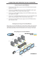
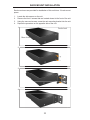
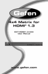
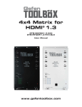
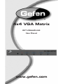
®
4x4 VGA Matrix
EXT-VGAAUD-444
User Manual
www.gefen.com
ASKING FOR ASSISTANCE
Technical Support:
Telephone
Fax
(818) 772-9100
(800) 545-6900
(818) 772-9120
Technical Support Hours:
8:00 AM to 5:00 PM Monday thru Friday Pacific Time
Write To:
Gefen LLC
c/o Customer Service
20600 Nordhoff St
Chatsworth, CA 91311
www.gefen.com
[email protected]
Notice
Gefen LLC reserves the right to make changes in the hardware, packaging and
any accompanying documentation without prior written notice.
4x4 VGA Matrix is a trademark of Gefen LLC
© 2011 Gefen LLC, All Rights Reserved
All trademarks are the property of their respective owners
Rev A4
CONTENTS
1
Introduction
2
Operation Notes
3
Features
4
Panel Layout
5
Panel Descriptions
6
Connecting And Operating The 4x4 VGA Matrix
7
IR Remote Description
8
4x4 VGA Matrix Remote Installation
9
Using the IR Remote Control Unit
10 RS-232 Interface
11 Rack Mount Installation
12 Specifications
13 Warranty
INTRODUCTION
Congratulations on your purchase of the 4x4 VGA Matrix. Your complete
satisfaction is very important to us.
Gefen
Gefen delivers innovative, progressive computer and electronics add-on solutions
that harness integration, extension, distribution and conversion technologies.
Gefen’s reliable, plug-and-play products supplement cross-platform computer
systems, professional audio/video environments and HDTV systems of all sizes
with hard-working solutions that are easy to implement and simple to operate.
The Gefen 4x4 VGA Matrix
The Gefen 4x4 VGA Matrix offers flexibility and convenience by routing highquality VGA and Analog Audio from any of four VGA/audio sources to any of 4
VGA displays and audio devices.
The Gefen 4x4 VGA Matrix works with a wide variety of VGA sources such as
computers, security cameras and DVRs. Every source is accessible at any time
by any display by selecting it with the included IR remote, front panel buttons, or
RS-232 control.
How It Works
Connect up to four VGA and Analog Audio sources to the 4x4 VGA Matrix’s
inputs. Connect the Matrix’s VGA and Analog Audio outputs to 4 VGA displays
and audio devices. Plug in the Matrix’s power supply. You may now switch VGA
and audio sources using the included IR remote, front panel buttons, or the builtin RS-232 serial port. LED lights on the front panel show the currently selected
routes from the VGA sources to the VGA displays.
1
OPERATION NOTES
READ THESE NOTES BEFORE INSTALLING OR
OPERATING THE 4X4 VGA MATRIX
•
The 4x4 VGA Matrix does not transmit display information (EDID) to the
source. Standard VESA resolutions should be output by most computers
without the need of an EDID. If using a non-VESA standard resolution or
if EDID is needed, an EDID storage and relay device is necessary. Gefen
recommends the use of a DVI Detective (part# EXT-DVI-EDIDN) with two
VGA to DVI adapters.
2
FEATURES
Features
•
Switches easily between any four VGA/Analog Audio sources
•
Sends up to four VGA inputs with Analog Audio to any four displays with
Analog Audio
•
Supports high-definition VGA up to 1920 x 1200 resolution at 60 Hz
•
LED lights on the front panel show selected VGA routes
•
RS-232 Control
•
Includes discrete IR remote control
Package Includes
(1) Gefen 4x4 VGA Matrix
(4) 6 ft. VGA Cables (M - F)
(4) 6 ft. 3.5mm, mini-stereo Analog Audio Cables
(1) 24V DC Power Supply
(1) IR Remote Control Unit
(1) Set of Rack Ears
(1) User Manual
3
PANEL LAYOUT
Front Panel
6
1
2
3
4
5
7
8
9
10
11
Back Panel
20
12
13
14
15
16
17
18
19
21
22
23
24
25
26
27
28 29
4
PANEL DESCRIPTIONS
1
Power LED
This LED indicator glows RED when power is connected properly and
sufficient power is being received by the Matrix.
2-5
Selected Input LED Indicators For Outputs 1-4
Each of the four output ports has an associated bank of 4 LED indicators that
shows which input source 1-4 is active for that output. The currently selected
input will be indicated by an active LED.
6
IR (Infrared) Receiver
This Receiver will accept commands for switching between VGA input
devices using the included RMT-16IR remote control.
7
Reset Button
The Reset button momentarily interrupts power, rebooting the unit and
resetting operational settings to defaults. This feature is useful if the Matrix
somehow becomes unresponsive.
8-11 Input Selection Button For Outputs 1-4
This button will set the source (1-4) for the indicated output. Each labeled
output on the front panel has this button. Each press of this button will cycle
through the four input sources that will be routed to that output.
12-15 Audio Inputs For Inputs 1-4
This 3.5mm mini-jack analog stereo input will accept a single audio source for
routing to the outputs. There are four inputs, one for each VGA input.
16-19 Audio Output For Outputs 1-4
This 3.5mm mini-jack analog stereo output will accept a single amplified audio
device. There are four outputs, one for each VGA output.
20
RS-232 Serial Communications Port
This DB-9 serial communications port allows the Matrix to be controlled
remotely by computers or control automation devices. Remote control devices
send routing commands to the Matrix via this port in the form of ASCII
characters. Please see page 10 for RS-232 Configuration.
21-24 VGA Inputs 1-4
These inputs will accept a single VGA source device. Any of these four VGA
inputs can then be routed in any combination to the four VGA outputs.
25-28 VGA Outputs 1-4
These outputs will accept a single VGA output device. Any of these four VGA
outputs can select and view one of the four VGA/Audio inputs.
29
24V DC Power Receptacle
Connect the included 24V DC power supply between this port and an open
wall power receptacle.
5
CONNECTING AND OPERATING THE 4X4 VGA MATRIX
How to Connect the 4x4 VGA Matrix
1.
Connect up to 4 VGA video sources to the 4x4 VGA Matrix inputs using the
supplied VGA cables.
2.
Connect up to 4 Analog Audio sources to the 4x4 VGA Matrix audio inputs
using the supplied 3.5mm mini-jack stereo audio cables.
3.
Connect up to 4 VGA capable displays to the 4x4 VGA Matrix outputs using
user supplied VGA cables.
4.
Connect up to 4 amplified Analog Audio devices to the 4x4 VGA Matrix audio
outputs using user supplied 3.5mm mini-jack stereo audio cables.
5.
Connect the included 24V DC power supply to the 4x4 VGA Matrix and an
open wall power socket.
Routing Sources Using the Front-Panel Buttons
Each output on the 4x4 VGA Matrix has a push-button located on the front panel.
Pressing this button will cycle through the 4 input sources. Press the button for
each display repeatedly to select the desired source for viewing on that output.
Wiring Diagram for the 4x4 VGA Matrix
MINI STEREO AUDIO CABLE
VGA CABLE
Computer
Computer
Computer
Computer
Switcher
VGA Monitor
VGA Monitor
VGA Monitor
RS-232 Controller
VGA Monitor
6
EXT-VGAAUD-444
IR REMOTE DESCRIPTION
1.
Remove battery cover from the back of the RMT-16-IR remote (see picture
below).
2.
Locate the DIP Switches and verify that DIP switches 1 & 2 are in the down
(OFF) position.
3.
Insert the battery, holding the battery so that you can see the positive side facing
up. The side that is not marked must be facing down.
4.
Test the RMT-16-IR remote by pressing ONLY one button at a time. The
indicator light on the remote will flash once each time you press a button.
WARNING: Do not press multiple buttons simultaneously and do NOT press buttons
rapidly. The remote will need to be reset and steps 1-4 will have to be repeated.
NOTE: The RMT-16-IR ships with two batteries. One battery is required for
operation, the second battery is a spare. Please see the pictures immediately below
for more information.
BACK
RMT-16IR
Remote
Control
Unit
Exposed DIP
Switches
Open Battery
Compartment
(Empty)
7
FRONT
4X4 VGA MATRIX REMOTE INSTALLATION
How to Resolve IR Code Conflicts
In the event that IR commands from other remote controls conflict with the
supplied RMT-16IR remote control, changing the remote channel will alleviate
this issue. The RMT-16IR remote control has a bank of DIP (Dual Inline Package)
switches (see page 7) for configuring the remote channel that both units use to
communicate. The 4x4 VGA Matrix can be put into a mode that will uses its front
LED array to indicate which remote channel is being used and also give the user
the ability to modify the currently used IR remote channel. These IR channel
settings must exactly match each other for proper operation.
The DIP Switch bank on the RMT-16IR is located underneath the battery cover
as shown on page 7.
Channel 1:
Default
Channel 2:
1
2
Channel 3:
1
2
1
2
Channel 4:
1
2
Left: Close-up picture of the opened rear battery
compartment of the RMT-16IR remote showing
the exposed DIP Switch bank between the battery
chambers.
Follow these steps to place the 4x4 VGA Matrix into IR channel setup mode.
1.
Turn on the 4x4 VGA Matrix.
2.
Press and hold the front panel POWER button for 5 seconds to enter the
setup mode (All output LED’s except for Output 1 will be off). The Output 1
LED source indicator (page 4) will display the currently selected IR channel.
The active LED, either 1, 2, 3, or 4, will indicate the IR channel being used.
3.
Note the IR channel used on the RMT-16IR remote and press the Output 1
selector button to cycle to the IR channel that is being used.
4.
Press the POWER button to save settings and exit IR channel setup mode.
Output-1
1
2
3
4
Channel 1
Output-1
1
Output-1
2
3
4
Channel 2
1
8
2
3
4
Channel 3
Output-1
1
2
3
4
Channel 4
USING THE IR REMOTE CONTROL UNIT
IR Remote Control Key Mapping
Each input and output on the 4x4 VGA Matrix is represented by a button on the IR
Remote Control unit. The table below lists the corresponding inputs and outputs.
RMT-16-IR
Button
Source
Output
RMT-16-IR
Button
Source
Output
1
1
1
9
1
3
2
2
1
10
2
3
3
3
1
11
3
3
4
4
1
12
4
3
5
1
2
13
1
4
6
2
2
14
2
4
7
3
2
15
3
4
8
4
2
16
4
4
Routing Sources using the IR Remote Control unit
Issuing a routing command is a two step process. The first step is to select the
monitor where the source will be routed. The second step is to select the source.
Example 1
Route the source device connected to In 7 to the monitor connected to Out 3.
1.
Press button 3 (monitor 3) on the IR remote control unit.
2.
Press button 7 (source 7) on the IR remote control unit.
The source connected to In 7 will be routed to the monitor connected to Out 3.
Example 2
Route the source device connected to In 1 to the monitor connected to Out 1.
1.
Press button 1 (monitor 1) on the IR remote control unit.
2.
Press button 1 (source 1) on the IR remote control unit.
The source connected to In 1 will be routed to the monitor connected to Out 1.
9
RS-232 SERIAL CONTROL INTERFACE
54321
12345
9876
6789
Only Pins 2 (RX), 3 (TX), and 5 (Ground) are used on the RS-232 serial interface
Binary Table
ASCII Corresponding
RMT16-IR
Button
1
1
2
2
3
3
4
4
5
5
6
6
7
7
8
8
Binary
ASCII
0011 0001
0011 0010
0011 0011
0011 0100
0011 0101
0011 0110
0011 0111
0011 1000
9
a
b
c
d
e
f
g
Corresponding
RMT16-IR
Button
9
10
11
12
13
14
15
16
Binary
0011 1001
0110 0001
0110 0010
0110 0011
0110 0100
0110 0101
0110 0110
0110 0111
Additional Features
ASCII
X or x
Y or y
Command
Power Off
Power On
RS-232 Settings
Bits per second ................................................................................................. 19200
Data bits .................................................................................................................... 8
Parity .................................................................................................................. None
Stop bits .....................................................................................................................1
Flow Control ....................................................................................................... None
10
RACK MOUNT INSTALLATION
Rack mount ears are provided for installation of this unit into a 1U rack mount
space.
1.
2.
3.
4.
Locate the side screws on the unit.
Remove the front 2 screws that are located closest to the front of the unit.
Using the removed screws, screw the rack mounting bracket into the unit.
Repeat the procedure on the opposite side of the unit.
1
Front of unit
Rear of unit
2
3
4
11
SPECIFICATIONS
Video Amplifier Bandwidth ........................................................................ 350 MHz
Input Video Signal ............................................................................... 1.2 Volts p-p
Input Sync Signal ......................................................................... 5 Volts p-p (TTL)
Horizontal Frequency Range .................................................................. 15-70 KHz
Vertical Frequency Range ...................................................................... 30-170 Hz
Video Connectors ........................................... 8 x HD15, female (4 input, 4 output)
Audio Connectors ................ 8 x 3.5mm mini-stereo jack, female (4 input, 4 output)
RS-232 Control Port ................................................................... 9-pin female DB9
Power Supply ............................................................................................... 5V DC
Power Consumption............................................................................. 20 W (max.)
Dimensions ..................................................................... 17” W x 3.5” H x 5.875” D
Shipping Weight .......................................................................................... 9.5 lbs.
12
WARRANTY
Gefen warrants the equipment it manufactures to be free from defects in material
and workmanship.
If equipment fails because of such defects and Gefen is notified within two (2)
years from the date of shipment, Gefen will, at its option, repair or replace the
equipment, provided that the equipment has not been subjected to mechanical,
electrical, or other abuse or modifications. Equipment that fails under conditions
other than those covered will be repaired at the current price of parts and labor in
effect at the time of repair. Such repairs are warranted for ninety (90) days from
the day of reshipment to the Buyer.
This warranty is in lieu of all other warranties expressed or implied, including
without limitation, any implied warranty or merchantability or fitness for any
particular purpose, all of which are expressly disclaimed.
1.
Proof of sale may be required in order to claim warranty.
2.
Customers outside the US are responsible for shipping charges to and from
Gefen.
3.
Copper cables are limited to a 30 day warranty and cables must be in their
original condition.
The information in this manual has been carefully checked and is believed to
be accurate. However, Gefen assumes no responsibility for any inaccuracies
that may be contained in this manual. In no event will Gefen be liable for
direct, indirect, special, incidental, or consequential damages resulting from
any defect or omission in this manual, even if advised of the possibility of such
damages. The technical information contained herein regarding the features and
specifications is subject to change without notice.
For the latest warranty coverage information, refer to the Warranty and Return
Policy under the Support section of the Gefen Web site at www.gefen.com.
PRODUCT REGISTRATION
Please register your product online by visiting the Register Product page
under the Support section of the Gefen Web site.
13
Rev A4
20600 Nordhoff St., Chatsworth CA 91311
1-800-545-6900
818-772-9100
www.gefen.com
Pb
This product uses UL listed power supplies.
fax: 818-772-9120
[email protected]