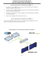
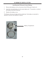
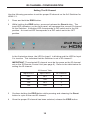
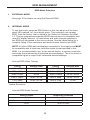
1
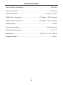
®
2x2 Switcher
for HDMI® 1.3
EXT-HDMI1.3-242
User Manual
www.gefen.com
ASKING FOR ASSISTANCE
Technical Support:
Telephone
Fax
(818) 772-9100
(800) 545-6900
(818) 772-9120
Technical Support Hours:
8:00 AM to 5:00 PM Monday thru Friday PST
Write To:
Gefen, LLC.
c/o Customer Service
20600 Nordhoff St
Chatsworth, CA 91311
www.gefen.com
[email protected]
Notice
Gefen, LLC reserves the right to make changes in the hardware, packaging and
any accompanying documentation without prior written notice.
2x2 Switcher For HDMI 1.3 is a trademark of Gefen, LLC
®
HDMI, the
logo, and High-Definition Multimedia Interface are
trademarks or registered trademarks of HDMI Licensing in the United States and
other countries.
© 2010 Gefen, LLC, All Rights Reserved
All trademarks are the property of their respective owners
Rev B2
2.1M
CONTENTS
1
Introduction
2
Operation Notes
3
Features
4
Panel Layout
5
Panel Descriptions
6
Connecting And Operating The 2x2 Switcher For HDMI 1.3
7
IR Remote Control Description
8
IR Remote Installation
9
IR Remote Configuration
10 IR Channel Configuration
11 EDID Management
11
Internal EDID
12
External EDID
13 Specifications
14 Warranty
INTRODUCTION
Congratulations on your purchase of the 2x2 Switcher for HDMI 1.3. Your
complete satisfaction is very important to us.
Gefen
Gefen delivers innovative, progressive computer and electronics add-on solutions
that harness integration, extension, distribution and conversion technologies.
Gefen’s reliable, plug-and-play products supplement cross-platform computer
systems, professional audio/video environments and HDTV systems of all sizes
with hard-working solutions that are easy to implement and simple to operate.
The Gefen 2x2 Switcher for HDMI 1.3
Gefen’s 2x2 Switcher for HDMI 1.3 is equipped with two HDMI inputs and two
HDMI outputs. Two inputs accommodate the simultaneous connection of up to
two high definition video sources, such as satellite systems and Blu-Ray players.
3D content can be displayed when connecting a 3DTV and 3D source. Two
outputs send the high definition audio/video signals to up to two HDTV displays.
Switching is done via the included IR remote.
How It Works
Connect all your sources to the 2x2 Switcher for HDMI 1.3 inputs. Then connect
up to two displays on the output ports. Once the sources, the switcher and the
displays are powered and connected, you then select which source you want to
view using the IR remote.
1
OPERATION NOTES
READ THESE NOTES BEFORE INSTALLING OR
OPERATING THE 2X2 SWITCHER FOR HDMI 1.3
•
By default, display information from the display connected to HDMI output port
1 is sent back to the source. Therefore, the other display connected to the 2x2
Switcher for HDMI 1.3 must be capable of accepting the timings, resolutions
and audio formats of the display that is connected to HDMI output port 1. It is
recommended that the display with the lowest native resolution be connected
to HDMI output port 1. This is to ensure that a compatible video signal will
be able to be displayed on all connected monitors. There is a generic EDID
programmed into the 2x2 Switcher for HDMI 1.3 that can be used instead. See
page 11 for more details.
2
FEATURES
HDMI 1.3 Features
•
225 MHz (up to 12 bit YUV 444 supported @ 1080p)
•
Deep Color
•
Dolby TrueHD and DTS-HD Master Audio
•
Lip-Sync
•
CEC Pass-Through
Features
•
Easily switch between any two Hi-Def sources on up to two (2) HDTV
displays without signal loss
•
Maintains sharp HDTV resolutions up to 1080p Full HD and 2K
•
3DTV Pass-Through
•
Color Space Conversion
•
EDID Management for rapid integration of sources and display devices.
•
Mono-LOK™ Locking HDMI Connectors
•
Supports the use of DVI sources and DVI displays with an HDMI-to-DVI
converter cable or adapter
•
HDMI and HDCP compliant
Package Includes
(1)
(2)
(1)
(1)
(1)
Gefen 2x2 Switcher for HDMI 1.3
6 ft. HDMI cables (M-M)
IR Remote Control Unit
5V DC Power Supply
User Manual
3
PANEL LAYOUT
Front Panel
1
2
3
4
5
6
Back Panel
7
8
9
10
4
11
PANEL DESCRIPTIONS
1
Power LED Indicator
This LED will become active once the included 5V DC power supply is properly
connected between the unit and a open wall power receptacle.
2
IR (Infrared) Receiver
This receiver will accept command for switching between input HDMI devices
using the included RMT-2IR remote control.
3
Internal EDID Mode LED Indicator
This LED will become active when the unit is using the pre-loaded EDID. See
page 11 for more details.
4
External EDID Mode LED Indicator
This LED will become active when the unit is using the EDID from the HDMI
deice connected to HDMI output port 1. See page 6 for more details.
5
Link LED Indicator
This LED will become active when the unit is properly connected to an HDMI
capable device on either of the HDMI output ports.
6
Input LED Indicators
There is one LED for each of the four input ports. The LED for the currently
selected HDMI input will be active.
7
EDID Button
This button will toggle between the internal external EDID modes. To determine
which mode is currently being used, please note which EDID mode LED is
active on the front panel of the unit.
8
Reset Button
This button will reset the unit and force all devices in the chain to re-transmit/
re-read EDID. It is essential that the unit be reset after the EDID mode has been
changed.
9
HDMI Input Ports 1-2
Connect up to 2 HDMI source devices to these HDMI input ports. Selection
between these inputs are made using the included RMT-2IR remote control.
10 HDMI Output Ports 1-2
Connect up to 4 HDMI capable devices to these HDMI output ports. The
currently selected HDMI input source device will be output through all of these
HDMI output ports.
11 5V DC Power Input Port
Connect the included 5V DC power supply between this port and an open wall
power receptacle.
5
CONNECTING AND OPERATING
THE 2X2 SWITCHER FOR HDMI 1.3
How to Connect the 2x2 Switcher for HDMI 1.3
1.
Connect up to two HDMI source devices to the 2x2 Switcher for HDMI 1.3
using the supplied HDMI cables.
2.
Connect up to four HDMI capable devices to the 2x2 Switcher for HDMI 1.3
using the supplied HDMI cables.
3.
Connect the included 5V DC power adapter to the 2x2 Switcher for HDMI
1.3 power input port.
4.
Power on the displays first and then the source.
How to Operate the 2x2 Switcher for HDMI 1.3
Use the included IR remote control unit to switch between HDMI inputs. See
page 7 for a description of the IR remote control.
Wiring Diagram for the Gefen 2x2 Switcher for HDMI 1.3
HDMI CABLE
HDMI 1.3 Source
HDMI 1.3 Source
Switcher/Splitter
HDTV
HDTV
E
EX
EXT-HDMI1.3-242
6
IR REMOTE DESCRIPTION
RMT-2IR Remote Control Unit
1
2
1
LED Button Press Indicator
This LED will be activated momentarily each time a button is pressed.
2
Display and Source Selection Buttons
These buttons are used to select which source is routed to the displays.
Example:
Route the source connected to Input 2 to the displays connected to Output 1 and
Output 2.
1.
Press button 2 on the IR remote control unit.
The source connected to Input 2 will be routed to the displays connected to Output 1
and Output 2.
7
IR REMOTE INSTALLATION
Installing the IR Remote Control Battery
1.
Remove the battery cover on the back of the IR Remote Control unit.
2.
Insert the included battery into the open battery slot. The positive (+) side of
the battery should be facing up.
3.
Replace the battery cover.
The Remote Control unit ships with two batteries. One battery is required for
operation and the other battery is a spare.
Battery Compartment
8
IR REMOTE CONFIGURATION
Setting the IR Remote Channel on the RMT-8IR
In the event that IR commands from other remote controls conflict with the
supplied IR Remote Control Unit, changing the remote IR channel will fix this
issue. The IR Remote Control Unit has a bank of DIP switches for setting the
Remote IR channel.
The DIP Switch bank is located underneath the battery cover.
Remote Channel 1:
Default
Remote Channel 2:
1
2
Remote Channel 3:
1
2
1
2
Remote Channel 4:
1
2
Left: Picture of the opened rear battery
compartment of the IR Remote Control
Unit showing the exposed DIP Switch bank
between the battery chambers.
The IR channel selected on the IR Remote Control unit must match the IR
channel assigned to the 2x2 Switcher for HDMI 1.3. For example, if you set both
DIP switches on the remote to the down position (IR channel 1), you must set the
2x2 Switcher for HDMI 1.3 to use IR channel 1.
Refer to page 10 on how to change the IR channel on the 2x2 Switcher for HDMI
1.3.
9
IR CHANNEL CONFIGURATION
Setting The IR Channel
Use the following procedure to set the proper IR channel on the 2x2 Switcher for
HDMI 1.3.
1
Press and hold the EDID button.
2
While holding the EDID button, press and release the Reset button. The
input LED indicators, on the front panel, will represent the current IR channel
for the Switcher: A blinking LED corresponds to DIP switch set to the ON
position. An inactive LED corresponds to a DIP switch set to the OFF
position.
In the illustration above, the LED for Input 1 is blinking and the LED for Input
2 is inactive. This indicates that the Switcher is set to IR channel 1.
IMPORTANT: The selected IR channel must be the same as the IR channel
set on the IR Remote Control Unit (see page 9). Refer to the table below for
setting the IR channel.
IR Channel Table
Input LED 1
Input LED 2
IR Channel
OFF
OFF
0
OFF
ON
1
ON
OFF
2
ON
ON
3
3
Continue holding the EDID button while pressing and releasing the Reset
button to cycle to the next IR channel.
4
Once the proper IR channel has been selected, release the EDID button.
10
EDID MANAGEMENT
EDID Mode Selection
1.
EXTERNAL MODE:
See page 10 for details on using the External EDID.
2.
INTERNAL MODE:
To use this mode, press the EDID button on the rear panel until the frontpanel LED marked “Int” turns bright green. This mode will use a preset
EDID, from the factory, that is stored in the Gefen 2x2 Switcher for HDMI
1.3. This pre-programmed standard EDID data structure is compatible with
most A/V display devices. All resolutions and audio formats specified in
this EDID will be passed to the source device. See the tables below for a
complete listing of the resolutions and audio formats listed in this EDID.
NOTE: All other HDMI devices/displays connected to the output ports MUST
be compatible with at least one resolution/audio format specified in this
EDID. It is recommended to set, on the source device, a common resolution
and audio format shared by all attached devices/displays. This is to ensure a
compatible signal is output to all connected devices/displays.
Internal EDID Video Timings
Timing
Refresh Rate
Timing
Refresh Rate
1280 x 720p
50 Hz
720 x 576p
50 Hz
1280 x 720p
59.94 / 60 Hz
1920 x 1080p
50 Hz
1920 x 1080i
50 Hz
1920 x 1080p
59.94 / 60 Hz
1920 x 1080i*
59.94 / 60 Hz
1440 x 480p
59.94 / 60 Hz
720 x 480p
59.94 / 60 Hz
1440 x 576p
50 Hz
* Native Resolution
Internal EDID Audio Formats
Audio Format
Supported Channels
LPCM
2CH
AC-3
2CH / 5.1CH
DTS
2CH / 5.1CH
11
EDID MANAGEMENT
External EDID Management
The 2x2 Switcher for HDMI 1.3 features EDID Management. Before the source
can send video or audio signals, the source device reads the EDID (Extended
Display Identification Data) from the output devices connected to the Splitter.
The EDID contains information about what type of A/V data that the source can
send to each output device.
The 2x2 Switcher for HDMI 1.3 distributes a single source to multiple output
devices. This involves reading EDID data from more than one device.
Management of the EDID data is important to maintain compatibility between all
devices.
The following EDID features are copied from Output 1:
•
Supported Resolutions
•
3D Support
•
Audio Features
EDID color features are built based on all attached displays, using the
following rules:
•
Deep Color will be enabled if one or more displays are connected to the
Splitter supporting Deep Color.
•
xvYCC (x.v.Color) is supported if all connected displays support it.
Display Connections:
•
If a display is not connected to Output 1, then no EDID changes are made,
meaning that the previous EDID information will be used. This state will be
in effect until a display is connected to Output 1 and the Splitter is powercycled.
•
EDID is built from Output 1 to the Input. The audio block will be copied
from Output 1. EDID-copying is performed only when the Splitter is reset or
power-cycled.
12
SPECIFICATIONS
Video Amplifier Bandwidth ............................................................... 225 MHz
Input Video Signal ...................................................................... 1.2 Volts p-p
Input DDC Signal ................................................................ 5 Volts p-p (TTL)
HDMI Input Connectors ........................................ (2) Type A, 19 Pin Female
HDMI Output Connectors ..................................... (2) Type A, 19 Pin Female
Power Supply ...................................................................................... 5V DC
Power Consumption .............................................................. 13 Watts (max)
Operating Temperature .................................................................... 0 - 40 °C
Dimensions ........................................................... 10.25” W x 1” H x 4.25” D
Shipping Weight ................................................................................. 3.5 lbs.
13
14
Rev B2
2.1M
20600 Nordhoff St., Chatsworth CA 91311
1-800-545-6900
818-772-9100
www.gefen.com
fax: 818-772-9120
[email protected]