1
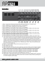
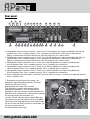
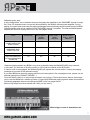
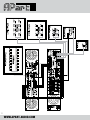
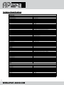
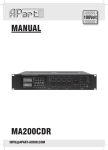
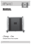
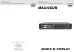
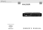
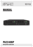
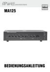
MANUAL
MA246/R/MR
[email protected]
Main features
The MA246 sets a new standard as a professional 6 zone PA mixing amplifier/preamplifier for
commercial and industrial applications, either as a standalone unit or as the central device in an
expandable, simple but clever paging system. The amplifier is equipped with 4 balanced mic/line inputs,
each with adjustable gain and tone controls and up to 4 line level inputs and an emergency input.
The MA246 has a six level priority system.
The emergency/telephone input has the highest priority and is activated by switch or vox circuitry. Its
signal goes directly to the main amplifier, bypassing any level control accessible at the front of the
unit, and an attenuator next to the input sets its level. Microphone input 1 has the second priority level,
followed by the mic 2, 3 and 4 and finally the line signals (music).
Zones 2 to 6 can be individually volume controlled using the integrated speaker volume controls.
Please note that zones number 5 and 6 are 70 volt outputs, these are compatible with 100 volt
speakers, but by nature, these outputs will have a slightly reduced output level, meant for the ‘quiet’
zones in a multizone system. For even more flexibility, zone 1 is an independent zone, with a separate
line level output, which turns the MA246 into a true 2 zone mixing amp with integrated preamp. During
paging, the corresponding integrated volume control will be automatically bypassed. When any priority
has been activated, integrated 24VDC supply output (max 0.6A) can activate priority relays of loudspeaker attenuators or other devices. Even an emergency 24 VDC supply input is present on the unit.
The supply will automatically keep the amplifier powered when mains power is interrupted.
Mic input 1 is optimized to be used with our MICPAT-6, a selective paging station 6 zone microphone.
This mic is the master mic. Maximum 5 of these mics can be switched in parallel on this single input !
Mic input 2 - 4 are designed to be used with our MICPAT-2 (2 zone groups) microphone or any other
microphone denpending on the application. On the MA246 unit you can preset 2 paging groups to be
paged with mic 2 – 4. Please note that it is not possible to connect multiple MICPAT-2 mics on the same
input.
That’s not all. If you are a professional installer, you will appreciate the possibility to use an external
amplifier as paging amp. Why ? Suppose zones 2 and 3 should not receive paging messages, meaning
there should always be background music. Then you can use an external amp for all paging tasks.
MA246 does all the switching and thinking for you. The internal amp will be used for background music.
When a paging message is sent to other zones than zone 2 and 3, zone 2 and 3 will stay connected to
the internal amplifier and will continue to enjoy the music. All other zones will hear the paging message:
the MA246 will disconnect these zones from the internal amp and will send the paging signal to the external amp. The external amp will feed the signal to the selected zones via the MA246. When paging is
finished, the zones will automatically be switched back to the internal amp. We will show an example of
such application in this manual. We will use a 2 channel PA2240BP amp and a MA246 in an application
that would normally use at least twice as much units to do all the switching and signal routing.
A unique new switching circuit design has been applied to ensure trouble-free switching during many
years.
Removable 19” brackets are shipped along with your amplifier.
The MA246 complies with the CE standards.
2
WWW.APART-AUDIO.COM
Front panel
1
2
3
15
16 17
4 5 6
18 19 20
7
8
21
9 10 11 12 13 14
22
23
24
1. Zone 1 output level: this level control sets the output level to the zone 1 preamp output.
2. Zone 1 paging led: this led lights up when zone 1 is being paged.
3. Zone 1 music selector: selects the line level input for zone 1.
4. Zone 2 paging led: this led lights up when zone 2 is being paged.
5. Zone 2 level control: this control is used to preset the zone 2 level in relation to the other zones.
6. Zone 3 paging led: this led lights up when zone 3 is being paged.
7. Zone 3 level control: this control is used to preset the zone 3 level in relation to the other zones.
8. Zone 4 paging led: this led lights up when zone 4 is being paged.
9. Zone 4 level control: this control is used to preset the zone 4 level in relation to the other zones.
10. Zone 5 paging led: this led lights up when zone 5 is being paged.
11. Zone 5 level control: this control is used to preset the zone 5 level in relation to the other zones.
12. Zone 6 paging led: this led lights up when zone 6 is being paged.
13. Zone 6 level control: this control is used to preset the zone 6 level in relation to the other zones.
14. Level indicators/clip-limit: The protect led lights up during startup during a few seconds, or when an
error occurs, such as overheating or overload. The lower green LED will light to indicate that power
is present. The signal led indicates that a strong signal is sent to the power amp. To work within
normal conditions the volume indicator should be kept under 0dB (100%). At -2,5dB a limiter will be
activated. This red LED indicates that the “auto gain circuit” keeps the level below clipping. This is
NOT a clip indicator, but an indication of the “automatic gain control”. Set your max levels so that
the limiter led never lights up !
15. Zone 2 – 6 music selector: selects the line level input for zones 2 - 6.
16. Music bass tone control
17. Music treble tone control
18. Music level control: turn this level knob to adjust the music level relative to the microphone signals.
19. Music muted by priority led: this red led lights up when the music is muted by any priority signal or
priority contact. When this led lights up, there is 24 VDC/0.6A available on the rear connector.
20. Mic/Line 2 level control: turn this knob to adjust the mic/line 2 level relative to other signals.
21. Mic/Line 3 level control: turn this knob to adjust the mic/line 3 level relative to other signals.
22. Mic/Line 4 level control: turn this knob to adjust the mic/line 4 level relative to other signals.
23. Master level control: turn this knob to set the global level in zones 2 – 6.
24. Power switch : switch mains power on and off. This switch turns off the amplifier when connected to
the mains AC supply. Please note that this switch does not switch the amp off when operating from
a 24 VDC emergency power supply.
3
[email protected]
Important information
Zone 2 - 6 level controls are used to preset levels in different zones relative to each other and to switch
off certain zones temporarily. Zone 5 and 6 outputs are 70 volts speaker line level outputs, these are
fully compatible with 100 volt speakers but will produce a maximum output level about 3 dB lower than
normal 100 volt lines. Use these outputs in the most silent zones. When using an external paging amp,
all speaker outputs from the selected zones are switched to maximum volume (100 volt) during paging, in
other words, the zone volume controls from zone 2-6 are bypassed.
A maximum of 180 watts speaker load is allowed per zone, with a total maximum of 240 watts for all
zones when using the internal MA246 power amplifier only. Do not overload the amplifier. If the amplifier is
overloaded, it will result in overheating the amplifier. Check your total speaker load with an impedance or
wattmeter before operating the amplifier. Minimum total speaker impedance (all zones combined) is calculated like this (100 V x 100 V) / 240 W = 41.66 ohms. Please note that impedance can NOT be measured
with a normal multimeter, you need a special impedance meter or 100 volt line wattmeter for this purpose.
In case you need more speakers and/or more power, use an external power amplifier for this purpose.
The MA246 has a separate preamplifier circuit for zone 1, and a combined pre-out/amp-in connector
for all other zones, allowing you to increase the total output power without the need of a supplementary
preamplifier.
Please note that in some cases the music level in non-pageable zones can slightly vary during paging.
When you use an external paging amp, the internal power amp will ‘see’ less speakers at its output,
because these speakers are switched to the external amp’s output during paging. This can result in music
levels varying, depending on the speaker load variation. This is not a malfunction. This effect will increase
depending on the speaker load variation. You can avoid such situations by powering the sensitive zones
with an external amplifier connected to zone 1 line level output.
4
WWW.APART-AUDIO.COM
Rear panel
2
1
18
4
3
6
5
7
8
9 10 11 12
19 20 21 22 23 24 25 26 27 28
13
14
29
30
15
31
16
32 33
17
1.Loudspeaker output connector zone 6 : zone 6 is a 70 volt speaker line output compatible with 100 volt
speaker lines. Com = speaker ground, 70 V = speaker plus connection. If this zone is selected for
paging, it will become a normal 100 volt line. Use this output for your ‘silent’ zones.
2. Loudspeaker output connector zone 5 : zone 5 is a 70 volt speaker line output compatible with 100 volt
speaker lines. Com = speaker ground, 70 V = speaker plus connection. If this zone is selected for
paging, it will become a normal 100 volt line. Use this output for your ‘silent’ zones.
3. Loudspeaker output connector zone 4 : zone 4 is a 100 volt speaker line output compatible with
100 volt speaker lines. Com = speaker ground, 100 V = speaker plus connection.
4. Loudspeaker output connector zone 3 : zone 3 is a 100 volt speaker line output compatible with
100 volt speaker lines. Com = speaker ground, 100 V = speaker plus connection.
5. Loudspeaker output connector zone 2 : zone 2 is a 100 volt speaker line output compatible with
100 volt speaker lines. Com = speaker ground, 100 V = speaker plus connection.
6. Zone 1 balanced line level output : this is the line level output for zone 1. Connect your optional external
zone 1 amplifier here.
7. Emergency input with priority contact : the
emergency input has highest priority. This level
can be set with knob ‘8’ only
and bypasses ALL other level controls.
The emergency signal is also present on the
preamp out connectors. You can activate the
emergency input by closing a contact between the
GND and prior connections, or alternatively, activate
the input by setting the automatic vox
circuitry. Set the internal jumper marked S3 to the
vox position and set the threshold level with VR13.
The jumper and level adjustment are located inside
the unit on the rear PCB. In order to reach them you
will need to open the unit.
For authorized persons only.
VR13 : Threshold
S3 : VOX
5
[email protected]
8. Emergency input level : this is the only level control on the emergency input. The emergency signal
bypasses all possible level controls in the MA246 unit.
9. Chime level: turn this knob to activate the two tone chime. The chime is activated by the priority
switches from mic/line 1 – 4. Please note that the emergency input switch or vox circuitry does not
activate the chime.
10. Paging group 1 dipswitches : click the dipswitches to the on position for zone 1 to 6 to enable zone 1
to 6 zone group paging with mic 2-4. Connect the GND and PG1 (paging group) connector on mic 2,
3 or 4 to the microphone paging switch. This will enable zone group 1 paging (e.g.using our MICPAT-2
unit). The dipswitch settings are valid for mic 2 – 4 inputs only. Mic 1 is a higher priority mic and
overrides these settings.
11. Paging group 2 dipswitches : click the dipswitches to the on position for zone 1 to 6 to enable zone 1
to 6 zone group paging with mic 2-4. Connect the GND and PG2 (paging group) connector on mic 2,
3 or 4 to the microphone paging switch. This will enable zone group 2 paging (e.g.using our MICPAT-2
unit). The dipswitch settings are valid for mic 2 – 4 inputs only. Mic 1 is a higher priority mic and
overrides these settings.
12. Selective paging connector on RJ45: connect the MICPAT-6 RJ45 connector to this connector for
selective zone paging. This is NOT a LAN or computer network connector, so NEVER connect this to
any other network.
Connection details:
Orange white cable: zone 1 – pin 1
Orange cable: zone 2 – pin 2
Green white cable: zone 3 – pin 3
Blue cable: zone 4 – pin 4
Blue white cable: zone 5 – pin 5
Green cable: zone 6 – pin 6
Brown white cable: GND – pin 7
Brown cable: +24V – pin 8
13. Mic 1 level, tone adjustment: adjust the mic 1 level and tone here. For use with MICPAT-6,
set the mic/line push button to the line position.
14. Mic/line 2: this mic has lower priority than mic 1; details, see below.
15. Mic/line 3: this mic has lower priority than mic 2; details, see below.
16. Mic/line 4: this mic has lower priority than mic 3; details, see below.
17. Fan section: the internal cooling fan operates when the amp temperature rises above 55°C.
Keep this area clear and clean.
Note: the fan is a mechanical device and the area around it needs te be kept clean at all times.
If the unit is used in a dusty environment, regularly clean out the entire amplifier with clean and
dry compressed air. Dust may collect inside the unit and prevent proper cooling, causing overheating,
eventually causing malfunction. Replace the fan if necessary. Failures caused by improper
maintenance are not covered by warranty.
18. Mains socket: connect the included mains power cord here. The mains fuse is also located inside the
socket. Replace it if necessary with an identical fuse only.
19. Backup power input: connect the 24 VDC backup power here. In case the mains voltage is
interrupted, the backup power will automatically keep the unit operational. Please note that maximum
output power of the internal power amp is limited when operating on the emergency supply.
20. Priority output: 24 VDC is present on this connector when priority is activated. You can use the 24
VDC to switch local volume controllers relays. Warning, maximum 0.6 A !!! Do not exceed maximum
output current, do not short circuit this output and do not apply any foreign voltage to this output !
6
WWW.APART-AUDIO.COM
21. Direct speaker outputs : This is the direct amplifier output, available in 100V, 70V and low impedance.
For normal operation, leave the 100V wire bridge between ‘22’ and ‘23’ in place. The wire bridge
connects the internal amp’s output to the integrated volume control and speaker switching circuitry.
22. External paging amp in: connect the 100V output from an external 500 Watt max paging amp here.
This is usefull in situations where you want to separate certain zones from each other, e.g. some
zones will need music only, other zones will need paging and music. The external amp will take care
of the power amplification of the paging messages. The MA246 takes care of all switching and
signal processing.
You will wonder why the external amplifier can be more than 240 watts ? Suppose you have a lot of
speakers connected to zone 5 and 6, these are the 70 volts zones by default. When powered by the
internal MA246 amp, the load on the internal amplifier is only half of the power compared to the
power in 100 volt. When you switch these zones to the external paging amp, these silent zones will
become 100 volt zones, meaning that the external amp will see double the power compared to the
internal amplifier.
23. External paging amp pre out: the line level signal for the external paging amp is present on
this balanced euroblock.
24. Paging mode switch: When pushed in, you can use an external paging amp. The external amp takes
care of the paging messages. When not pushed in, all signals are amplified by the MA246 internal
amp only.
25. Power amp in – pre out: here you can connect an external signal processor, e.g. an equalizer. In all
other cases, leave the signal bridge in place or there will be no output from the power amplifier.
You can use a Y connector here to feed the line signal to an external device.
26. Aux 3 – aux 4 inputs: mono inputs aux 3 and aux 4.
27. Aux 2: aux 2 stereo input, stereo signals are internally mixed to mono.
28. Aux 1: aux 1 stereo input, stereo signals are internally mixed to mono.
29. Paging mic 1: input for mic 1 on balanced euroblock. Both mic and line levels are supported.
For operation with micpat 6, switch to line level operation with the mic/line selector switch, located
above the euroblock. This mic has priority level 2
30. mic/line 2 input, this mic has priority level 3, for details about the mic channel strip, see below.
31. mic/line 3 input, this mic has priority level 4, for details about the mic channel strip, see below.
32. mic/line 4 input, this mic has priority level 5, for details about the mic channel strip, see below.
33. GND screw.
Note: please do not remove the cover labeled ‘OPTIONAL MODULE SLOT’. This is meant for future
expansion modules not available at this moment.
7
[email protected]
Microphone connections
Status dipswitches: set to * when using a microphone with a
push button(s) connected to the paging contact(s). Set to mix
when you want the speech to be mixed with the music: this is
usefull for mics without pushbuttons or switches.
Phantom power: set to on if your microphone needs phantom power (such as condenser mics).
Voltage supplied is 18 VDC.
Signal input: balanced input on euroblock. This connector accepts balanced and unbalanced mic/line
signals. For use with unbalanced mics or line level signals, connect the source GND to both GND and
-, connect the unbalanced hot wire to +. This can be usefull when connecting the receiver output from a
wireless microphone. Connection example using an unbalanced source:
Unbalanced MIC/LINE signal connection
Alternatively, you can connect the unbalanced signal ground to the – connector and the ‘hot’ wire to the +
connector. By leaving the ground connection unused, you can avoid a lot of ground loop problems (such
as hum, excessive noise…)
Unbalanced MIC/LINE signal connection
8
WWW.APART-AUDIO.COM
Priority levels
Paging switch connector: for selecting paging in zone 1 or zone 2 group. MIC1 will always override the
zone group preselection.
Paging group 1: connect GND to PG1 using a switch. Do not apply external voltages to these contacts.
Paging group 2: connect GND to PG2 using a switch. Do not apply external voltages to these contacts.
Note: MICPAT-2 is equipped with 2 switches for paging 2 zone groups and can be connected to the
euroblock connector.
The mic/line inputs all have different priority levels according to the table below:
MICPAT-2 connection
MICPAT-2 (or other paging mic) can be connected to MIC/LINE 2 -4, depending on the priority level
required (see priority level table). Connect red wire to +, white wire to -, shield+yellow wire to GND, black
wire to PG1, blue wire to PG2. You can preset the paging groups 1 and 2 using the dipswitches at the rear
of the MA246. The paging group settings are equal for mic 2 to 4.
MICPAT-6 connection
MICPAT-6 must be connected to the PAGING INPUT 1 : connect the RJ45 plug to the selective paging
station RJ45 connector. The second wire, the one with the blank leads must be connected to the SGL input euroblock : screen (black) to GND, blue to -, brown to +. The MIC1 level can be set using the controls
on the rear only. You can connect up to 5 pcs MICPAT-6 units to this input. Use one or more RJ45 split
units to connect the RJ45 connectors from the mics to the RJ45 connector. The SGL input of all
MICPAT-6’s must be connected in parallel on the SGL input euroblock.
RJ45SPLIT
9
[email protected]
Speaker ZONE connections
Zone 1 amplifier connection (e.g. 480 watts in zone 1):
Connect the signal output zone 1 (balanced, on euroblock) to the external amplifier’s signal input, e.g. our
PA2240BP in bridge mode, providing 480 watts into 100 volt. Zone 1 has independent line source selection and volume control.
The benefit of the 70 volt and 100 volt output zones :
The 70 volt outputs from zone 5 and 6 are fully compatible with 100 volt speakers. In silent zones, such
as toilets or showroom areas, the 100 volt speakers usually play at very low levels, even far below 70 volt.
However, when paging is needed in these zones, full power at 100 volt might be required. Zone outputs
5-6 are specially designed for any application where a clear (louder) speech paging is required above the
normal background music level. Zones 2-3-4 outputs are standard 100 Volt for both speech and background music. Of course, the level of BGM in each zone can be adjusted or even switched off (paging
only) by the zone level controls on the front panel.
Using an external paging and/or zone 1 amplifier :
The external paging amplifier must have at least the same power as the internal MA246 amplifier. By connecting an external paging amp, you have the possibility to create independent zones with different sound
levels with a very simple setup. You can use our PA240P for this purpuse, or even the PA2240P-2 channel amp. The second PA2240P channel can be used as zone 1 amplifier, e.g. to power the speakers in a
warehouse or production facility, where music source and level requirements are different from the other
zones, such as office areas, boardrooms, showroom…Another possibility is to use the PA240P as paging
amp, and use the PA2240P in bridge mode in zone 1, this offers you 480 watts in zone 1. The benefits are
clear: less wiring, easy installation, flexible routing, possibility to have zones with extremely high power
demands controlled by one central unit, the MA246.
Zone connection examples :
Zone 1 = production facility and parking area: independent source selection, 480 watts from PA2240BP in
bridge mode.
Zone 2-4: office area, showroom and boardroom : from internal amp, pageable.
Zone 5-6 (70 volt outs): toilets, hallway : the most silent zones in this case powered by internal amp, non
pageable.
The external paging amp (e.g. PA240P or PA2240BP) takes over the pageable zones, zone 2-4 in this
case, while the other zones continue to hear the music without interruption from the paging messages.
Notes:
What happens if you use the MA246 as a standalone mixing amplifier, without external paging amp ?
The pageable zones 2-4 will hear the paging messages amplified by the internal MA246 power amplifier,
the non pageable zones 5-6 will be silent.
Suppose pageable zones 2-4 internal volume controls are set at a very low level (or even switched off
completely…). What happens if these zones are paged ?
MA246 will automatically bypass the (internal) volume controls during paging, this means that the pageable zones will hear the paging message at full power, even if the MA246’s internal volume controls are
switched off.
What about external volume controls ? If you use additional external volume controls, such as our E-VOL
series, be sure to connect the 24 volt priority output from the MA246 to the volume control’s 24 V priority
input. This will bypass the external volume controls, allowing paging messages to be heard at full power.
Practical wiring example when using the PA2240BP as dedicated zone 2-6 paging amp and as ZONE1
10
WWW.APART-AUDIO.COM
240watts power amp:
In this configuration, zone1 selected sources will always be amplified by the PA2240BP channel 2 amplifier. Zone 2-6 selected music sources will be amplified by the MA246 internal power amplifier. During
paging, the zones that must hear the paging messages are automatically disconnected from the MA246
internal amplifier and will be switched to the PA2240BP channel 1 amplifier. The internal MA246 power
amplifier will continue to play the music in the non-paged zones.
Setup
MA246(R/MR)
MA246 (R/MR) +
Paging
amplifier
MA246 (R/MR) +
Zone1
amplifier
ma246 (R/MR) +
zone1 + paging
amplifier
5 zone individual
volume control with
priority bypass
Yes
yes
yes
yes
6 zone operation with
independent zone1
source selection
no
no
yes
yes
selective paging
yes
yes
yes
yes
selective paging without background music
interuption
no
yes
no
yes
*Selective paging without any BGM in any zone is possible using the MA246(R)(MR) only, however,
in this case, you will have to turn the zone 2 to 6 front volume control to the off position.
In case a zone is being paged, the MA246(R)(MR) will bypass the volume control, causing the paging
message to be heard in the selected zone(s).
If you want BGM and selective paging without music interruption in the non paged zones, please use an
external paging amp (PA240P, PA2240P…).
From the factory, there is no wire bridge as shown in the picture. That’s because we want to encourage
you to use the MA246 as a switching centre in high quality BGM and paging systems where all zones are
individually pageable without interrupting the BGM in the non paged zones.
Most mixing amps from other brands don’t offer you this luxury.
Wire bridge in case of standalone use.
11
[email protected]
12
WWW.APART-AUDIO.COM
MA246R
3
15
Difference in MA246R front panel controls:
Music selector 3 and 15 have 3 aux source inputs + internal tuner (MA246 has 4 aux source inputs).
On the left side of the front panel you will find a digital tuner. Operation of the tuner will be explained later.
26
34
Difference in MA246R rear panel layout:
Aux 4 mono input (26) has been replaced by a rec out output bus.
Antenna connector (34) for AM wire antenna and FM antenna coax connector.
Please note that you must use a HF ground isolation transformer when connecting the FM antenna
input to an active antenna or cable network !
13
[email protected]
MA246MR
3
15
Music selector 3 and 15 have 2 aux source inputs + internal tuner and CD/MP3 section (MA246 has 4 aux
source inputs).
On the left side of the front panel you will find a digital tuner and the CD/MP3 player. Operation of the
tuner and CD/MP3 player will be explained later.
26
34
Difference in MA246MR rear panel layout:
Aux 3 & 4 mono input (26) have been replaced by a rec out and tuner output bus.
Antenna connector (34) for AM wire antenna and FM antenna coax connector.
Please note that you must use a HF ground isolation transformer when connecting the FM antenna
input to an active antenna or cable network !
14
WWW.APART-AUDIO.COM
Tuner operation
1
7
2
3
4
5
6
8
9
10
11
12
1. Display section: shows various tuner parameters such as frequency band (FM or AM), selected
frequency and preset number. The tuner has 10 AM and 10 FM preset memory locations.
2. FM/AM selector: press to switch between FM or AM band.
3. Scan down: press shortly to scroll one step down in the frequency band (9 kHz AM, 50 or 100 kHz FM).
Press for about a second to search for the next radio station down the frequency band.
4. Scan up: press shortly to scroll one step up in the frequency band (9 kHz AM, 50 or 100 kHz FM).
Press for about a second to search for the next radio station up the frequency band.
5. Scan button: press to scan all memory locations: the tuner automatically selects the next memory
location every 3 seconds. After a full scan, the tuner resumes to normal operation. You can interrupt
the scan cycle by pressing the scan button during the memory scan.
6. Save button: press this button, followed by a numeric button (1 to 5, +5) to store a preset in the internal
memory. E.g., you want to store the currently selected station in memory location number 1: press the
save button, followed by the numeric 1 button. If you want to save in locations 6 to 10: press the save
button first, then the +5 button followed by a numeric button 1 to 5 -> preset 6 = button +5 followed
by button 1…
7. Numeric button 1: press to select or save preset 1
8. Numeric button 2: press to select or save preset 2
9. Numeric button 3: press to select or save preset 3
10. Numeric button 4: press to select or save preset 4
11. Numeric button 5: press to select or save preset 5
12. Numeric button +5: press this button first to select or save preset stations 6 to 10, followed by a
numeric button 1 to 5. Alternatively, during manual frequency scan, you can press this button to
select a half frequency step, e.g. FM steps are 100 kHz by default, press the +5 button to step
up 50 kHz in the FM band.
Note: after powering on the MA246R/MA246MR main unit, the tuner is automatically powered on.
15
[email protected]
CD/MP3 operation
1
9
10
11
2
3
4
5
6
7
8
12
13
14
15
16
17
1. Display section: shows various parameters such as track number, folder number (if present),
elepased track time, CD mode, MP3 mode…
2. CD slot: insert the CD carefully in this CD slot. Do not apply force, you might damage the loading
mechanism. If the unit refuses to accept a CD, press the stop/eject button repeatedly to
reset the loading mechanism.
3. Repeat: press this button to alternate between repeat 1 (repeat one track), repeat folder or
repeat all. Repeat mode is shown in the display.
4. Shuffle: press once to activate the shuffle function. The unit will play a randomly selected track.
To exit shuffle mode, press the button once again. Shuffle mode is shown in the display.
5. Folder <<: press this button to select the previous folder. This button has no function when
no folders are present on the media (MP3 CD, USB or CARD slot).
6. Folder>>: press this button to select the next folder. This button has no function when no
folders are present on the media (MP3 CD, USB or CARD slot).
7. Track<<: press once (short) to select the previous track, keep pushing to search backward in
the track currently playing.
8. Track>>: press once (short) to select the next track, keep pushing to search forward in the
track currently playing.
9. USB slot: insert your USB memory stick here. Please note that an external USB hard disk may
not work on these slots. File system recognized is FAT32, maximum memory size is up to
32 gigabytes. Some USB sticks don’t allow direct memory access. These will not work
on the MA246MR.
10. IR eye: infrared receiver eye: receives IR signals from the optional IR remote.
This remote controls the CD/MP3 player only.
11. MMC/SD card slot: push in the card gently, metal contacts first, pointing down. Push the card
in until you hear a click. Push the card again to eject. File system recognized is FAT32,
maximum memory size is up to 32 gigabytes.
12. Select CD-USB-CARD: press this button to select CD, USB or memory card operation.
13. Prog button: press this button to enter program mode. Press a second time to quit program mode,
or press stop to clear all program steps. Programs are not memorized after powering on and off.
If you enter program mode, PROGRAM is displayed in the display, the numeric characters show
folder number, track number and program step number. Enter program mode, select a folder and
track and press shuffle to enter the selected folder/track. The last last characters show the program
16
WWW.APART-AUDIO.COM
step. Select another folder/track and press shuffle to confirm the program step. When you press
shuffle twice, the selected track will be played twice… After programming all steps, press play
to start playing the program. In order to clear the program, press program or stop to clear the
program steps. Programs can not be stored or recalled.
14. Mute button: press once to mute the CD/MP3, press again to unmute.
15. Play/pauze: press to start playback, press again to pauze playback.
16. Stop/eject: press to stop playback or to eject the CD media if present.
17. Power button: press to power on or off the CD/MP3 player. By default, the CD/MP3 unit must
be powered on manually after powering on the MA246MR unit.
Note: the CD player will play normal audio CD’s and CDR’s containing PCM audio files or wav files,
MP3’s or WMA files. The USB and CARD reader will only read MP3’s or WMA files. ID3 tag and folder
names are not displayed. For maximum compatibility, avoid media containing other than the supported
file types.
17
[email protected]
Technical Specifications
SPECS
MA246
‐
MA246R
‐
MA246MR
GENERAL
SPECS
!utput
power
ra+ng
RMS
Frequency
response
100
volt
out
Total
harmonic
distor+on
Frequency
response
line
output
zone
1
Bass
tone
control
zone
2‐6
Treble
tone
control
zone
2‐6
Tone
control
mic/line
1‐4
S/N
ra+o
(20Hz‐20kHz)
Indicator
leds
Zone
controls
Source
controls
Power
supply
Mains
fuse
ra+ng
Emergency
supply
fuse
Priority
output
fuse
Weight
net
MA246
‐
MA246R
‐
MA246MR
Shipping
weight
MA246
‐
MA246R
‐
MA246MR
Dimensions
Shipping
dimensions
!pera+ng
temperature
and
humidity
240
wa4
40
‐
25
kHz
+1/‐3dB
<0,3%
@
‐6dB,
1kHz
20
‐
30
kHz
+1/‐3dB
+8/‐
8dB
@
100Hz
+8/‐8dB
@
10kHz
from
100Hz/+3dB,
10kHz/‐6dB
to
100Hz/‐9dB,
10kHz/+4dB
amplifier
in:
>95dB
line
in:
>80dB
mic
in:
>65dB
zone
paging
:
6
x
yellow
led
muted
by
priority
:
1
x
red
led
Limiter
ac+vity
:
1
x
red
led
Signal
100%
:
1
x
yellow
led
Signal
‐25dB
:
1
x
green
led
Power
on
:
1
x
green
led
Protec+on
ac+ve
:
1
x
red
(also
lights
up
during
power
on)
Individual
volume
and
source
selec+on
for
zone
1
line
output
5
x
100
volt
volume
controls
for
zone
2‐6
Music
selector
zone
2‐6
Music
selector
zone
1
music
level
control
zone
2‐6
mic/line
2‐4
volume
control
all
zones
Master
level
control
zone
2‐6
Master
level
control
zone
1
Chime
level
control
(back
panel)
Emergency
level
control
(back
panel)
Emergency
vox
on/oa/level
control:
sebng
inside
the
unit
230VAC/50‐60Hz
MAX
800
VA
T6,3AL250V
(inside
mains
connector
on
back
panel)
T20AL250V
(inside
the
unit)
0,6A
rese4able
autofuse
13,6
kg
‐
13,8
kg
‐
14,4
kg
430(w)
x
88
(h)
x
360
(d)
‐
2
HE,
19"
brackets
included
‐10
to
+45°C/up
to
90%
RH
non
condensing
OUTPUTS
Zone
1
Zone
2‐6
Separate
speaker
out
Rec
out
(MA246R/MR
only)
Tuner
out
(MA246MR
only)
Pre
amp
out
zone
2‐6
Phantom
power
Pre
amp
out
zone1
Paging
amp
out
Priority
out
Chime
Line
level
output,
balanced
0
dB
on
euroblock
connector
100V
outputs,
zone
5
and
6
are
limited
to
70V
compa+ble
with
100V
speakersk
MAX240
wa4
total
power
in
100V
(180
wa4
max
in
1
zone)
Preselectable
output
levels:
5
steps
+
oa
+
automa+c
bypass
(priority)
Minimum
load
impedance
all
zones
summed
:
41,66
ohms
Zone
2‐6
outputs
on
euroblock
connector,
amplifier
power
can
be
supplied
by
internal
or
external
amp
(selectable
with
paging
mode
switch
at
the
back
panel)
50V/70V/100V
and
low
impedance
on
euroblock
1V
300
mV
1
V
18
VDC
1
V
balanced
on
euroblock/100
ohm
output
impedance
2
V
balanced
on
euroblock/100
ohm
output
impedance
24VDC,
max
0,6A
2
tone
chime
ac+vated
by
contact
closure
INPUTS
MIC/LINE
1
balanced
input
on
euroblock
Sensi+vity
mic/line
Impedance
S/N
mic/line
Phantom
power
Frequency
response
Mu+ng
ac+vated
by
contact
variable
3mV
to
2V
600
ohm
>65dB/>80dB
NA
80Hz
‐
15kHz
(+1/‐3dB)
speech
eq
mutes
inputs
with
lower
priority
by
more
than
40dB
MIC/LINE
2‐4
balanced
inputs
on
euroblock
Sensi+vity
mic/line
Impedance
S/N
mic/line
Phantom
power
Frequency
response
Mu+ng
ac+vated
by
contact
variable
1,5mV
to
200mV
600
ohm
>65dB/>80dB
18
VDC
80Hz
‐
15kHz
(+1/‐3dB)
speech
eq
>
40dB;
priority
according
to
priority
table
18
WWW.APART-AUDIO.COM
EMERGENCY
INPUT
transformer
coupled
balanced
input
on
euroblock
Sensi&vity
Impedance
S/N
Frequency
response
Mu&ng
AUX
1
‐
2
unbalanced
stereo
input
on
RCA
Sensi&vity
Impedance
S/N
Frequency
response
AUX
3
‐
4
unbalanced
mono
input
on
RCA
Sensi&vity
Impedance
S/N
Frequency
response
1V
600
ohm
>80dB
100Hz
‐
20
kHz
(+1/‐3dB)
Ac&vated
by
contact
or
vox
(selectable
inside
the
unit)
Emergency
has
highest
priority
and
mutes
all
other
inputs
by
more
than
40
dB.
The
signal
is
also
present
on
the
preamp
out,
500mV
22
kilo
ohm
>80dB
40
‐
25
kHz
+1/‐3dB
Signal
is
internally
mixed
to
mono
500mV
22
kilo
ohm
>80dB
40
‐
25
kHz
+1/‐3dB
TUNER
(MA246R/MR
only)
Tuning
range
FM
band
Tuning
range
AM
band
Aerial
terminal
AM
Aerial
terminal
FM
Sensi&vity
FM
S/N
FM
band
Sensi&vity
AM
Harmonic
distor&on
FM
band
Frequency
response
FM
band
Number
of
presets
87,5
‐
108
MHz
(100
kHz/50
kHz
tuning
step)
531
‐
1602
kHz
(9
kHz
tuning
step)
AM
antenna
spring
lock
terminal
75
ohm
coax
connector
1
µV/75
ohm
at
26
dB
S/N
>
74
dB
at
40
kHz
devia&on
40
µV
(26
dB
S/N)
<
0,1%
at
preamp
and
tuner
output
30
Hz
‐
15
kHz
(+1/‐3
dB)
at
preamp
and
tuner
output
10
FM,
10
AM
CD/MP3/WMA
(MA246MR
only)
Frequency
response
Harmonic
distor&on
Supported
file
types
CD/CDR
Supported
file
types
USB/CARD
File
system/capacity
USB/CARD
20
Hz
‐
20
kHz
(+0/‐1
dB)
at
preamp
output
<
0,01%
at
preamp
output
PCM
16
bit/44,1
kHz,
MP3
32
‐
320
kbps,
variable
bit
rate
MP3
32
‐
320
kbps,
variable
bit
rate,
WMA
FAT32
up
to
32
gigabyte
APart-audio general waranty conditions
APart-Audio warrants this product to be free of defects in material and workmanship for a period of one* year for
parts and for a period of one* year for labor from the date of original end-user purchase.
This warranty is valid only for the original end-user and cannot be transferred.
During the warranty period APart-Audio or one of its authorized service partners shall either repair or replace any product,
free of charge, that proves to be defective on inspection by APart-Audio or its authorized service representative.
All warranty claims must be accompanied by a detailed description of the problem.
All returns must be sent to APart-Audio or an authorized APart-Audio repair centre, postage prepaid, insured and properly
packaged. Proof of purchase must be presented in the form of a valid invoice or some other positive proof that
the product is within the warranty period.
This warranty does not cover any defects caused by faulty installation, damage due to abuse, neglect,
alteration or attempted repair by unauthorized personnel, system mismatch, insufficient maintenance or any damage
caused by excessive mechanical stress and is strictly limited to failures arising during normal use that are due
to defects in material or workmanship in the product.
Under no circumstance, APart-Audio or one of its service centres can be held responsible for the loss of data caused by a
repair or exchange operation.
APart-Audio reserves the right to change or improve the design and/or specification of the product at any time
without prior notice.
*warranty period may be different for your country. Please consult your local dealer.
19
[email protected]
Safety Instructions
• Please check the carton box for any kind of damage on reception of the goods. In case of a damaged
carton, please contact your dealer before opening the carton.
• !!!! Danger !!!! Exposure to extremely high noise levels may cause a permanent hearing loss. Individuals
vary considerably to noise induced hearing loss but nearly everyone will lose some hearing if exposed to sufficiently intense noise for a sufficient amount of time. Therefore it is recommended that all persons exposed
to equipment capable of producing high sound pressure levels, such as this amplifier, be protected by hearing protection while installing or operating this unit.
• Read all documentation before operating your equipment.
• Keep all documentation for future reference.
• Save the carton and packing material even if the equipment has arrived in good condition.
• Should you ever need to ship the unit, use only the original factory packing.
• Do not spill water or other liquids into or on the unit.
• Make sure power outlets conform to the power requirements listed on the back of the unit.
• Do not use the unit if the electrical power cord is frayed or broken.
• Have gain controls on amplifiers turned down during power-up to prevent speaker damage if there are high
signal levels at the inputs.
• Do not connect the inputs / outputs of amplifiers or consoles to any other voltage source, such as a battery,
mains source, or power supply, regardless of whether the amplifier or console is turned on or off.
• Power down & disconnect units from mains voltage before making connections.
• Do not use the unit near stoves, heat registers, radiators, or other heat producing devices.
• Do not operate equipment on a surface or in an environment which may distort the normal flow of air
around the unit. If the unit is used in an extremely dusty or smoky environment, the unit should be periodically “blown free” of dust.
• Do not remove the cover. Removing the cover will expose you to potentially dangerous voltages.
• Do not drive the inputs with a signal level higher than that required to drive equipment to full output.
• Do not run the output of any amplifier back into another input.
•In case of mal-function this device should be serviced by qualified service personnel only.
MA246 is developed by
Audioprof nv
Lanteernhofstraat 90
BE-2100 Deurne
BELGIUM
20
WWW.APART-AUDIO.COM