1
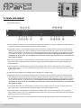
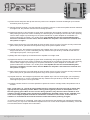
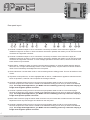
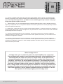
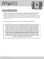
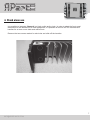
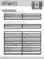
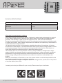
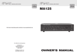
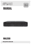
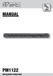
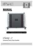
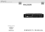
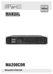
MANUAL
Champ - 4
Professional quad power amplifier
[email protected]
Safety First!
•
•
•
•
•
•
•
•
•
•
•
•
•
•
•
•
•
•
•
•
•
Caution: hot and sharp surfaces ! This professional device needs to be installed by
qualified personnel only.
Please check the carton box for any kind of damage on reception of the goods. In case of a
damaged carton, please contact your dealer before opening the carton.
!!!! Danger !!!! Exposure to extremely high noise levels may cause a permanent hearing
loss. Individuals vary considerably to noise induced hearing loss but nearly everyone will lose
somehearingifexposedtosufficientlyintensenoiseforasufficientamountoftime.Therefore
it is recommended that all persons exposed to equipment capable of producing high sound
pressurelevels,suchasthisamplifier,beprotectedbyhearingprotectionwhileinstallingor
operating this unit.
Read all documentation before operating your equipment.
Keep all documentation for future reference.
Save the carton and packing material even if the equipment has arrived in good condition.
Should you ever need to ship the unit, use only the original factory packing.
Do not spill water or other liquids into or on the unit.
Make sure power outlets conform to the power requirements listed on the back of the unit.
Do not use the unit if the electrical power cord is frayed or broken.
Always operate the unit with the AC ground wire connected to the electrical system ground.
Havegaincontrolsonamplifiersturneddownduringpower-uptopreventspeakerdamageif
there are high signal levels at the inputs.
Donotconnecttheinputs/outputsofamplifiersorconsolestoanyothervoltagesource,such
asabattery,mainssource,orpowersupply,regardlessofwhethertheamplifierorconsoleis
turned on or off.
Power down & disconnect units from mains voltage before making connections.
Do not use the unit near stoves, heat registers, radiators, or other heat producing devices.
Donotoperateequipmentonasurfaceorinanenvironmentwhichmaydistortthenormalflow
of air around the unit. If the unit is used in an extremely dusty or smoky environment, the unit
should be periodically “blown free” of dust.
Do not remove the cover. Removing the cover will expose you to potentially dangerous voltages.
Do not drive the inputs with a signal level higher than that required to drive equipment to full
output.
Donotruntheoutputofanyamplifierbackintoanotherinput.
Do not ground the red output terminal, never connect a red output terminal to another red
output terminal.
Incaseofmal-functionthisdeviceshouldbeservicedbyqualifiedservicepersonnelonly.
2
WWW.APART-AUDIO.COM
Manual contents
1. Features
2. Inputs and outputs
3. Rack mounting and wiring
4. standalone use
5. Technical specifications
1. Features
•
•
•
•
•
•
•
•
•
•
ustomdesignedsidemountheatsinks,fourdiscreteclassABamplifiersinaoneunit19”
C
enclosure.
Switchablehighandlowpassfiltersforeasyandtroublefreesubwoofer/satelliteapplications.
IntegratedAPClimitercircuitryandclipindication.Thisintelligentcircuitwillpreventharsh
distortion caused by clipping, provided that the input signal itself is not distorted of course…
what goes in, comes out.
Bridgeablepoweramplifiers:doubletheoutputpowerbyunitingthepowerof2amplifiers.
Minimum load impedance in bridge mode is 8 ohms.
Self-supportinglowresonanceframe.Torsionfreefrontandsidepanelconstructionwith
integrated heatsink assembly.
Solidaluminumbrushedfrontpanelwithremovable19”bracketsandhandlesforuseina
rack,noadditionalsupportneeded.Withoutthe19”bracketsitwillbeastandaloneunitin
high quality audio systems.
High power toroidal transformer.
Low impedance power supply for improved dynamic response.
Solid speaker binding posts.
4 sets of banana screw plugs included.
3
[email protected]
2. Inputs and outputs
Frontpanellayout:
2
1
6
3
7
4
8
5
12 13 14 15
9
10
11 16 17 18
19
1)Volumepotmeterchannel1:usethispotmetertopresetthevolume.Incasetheamplifierhasbeenswitched
to bridge mode, this potmeter sets the level for bridge operation.
2)Signalledchannel1:thisledlightsupgreenwhenasufficientlystrongsignalispresentonthefirstchannel,
after passing the input level control. At startup, the led will light up red during a few seconds, this is perfectly
normal.Whenitlightsupredduringuse,thepowertransformerorpoweramplifierisoverheatedorinprotect
modeandisshutdown.Turnoffthepower.The amplifier will not turn on automatically after most error
conditions. In some cases, the user MUST turn off power, remove the overload or let it cool down and
then power on again !
3)APCactivityledchannel1:thisledlightsupwhentheAPCcircuitryisactive.TheAPCcircuitryreducesthe
gainattheinputstoguaranteethefulldynamicrangeofthepoweramplifiercircuits,withoutallowingany
harsh distortion.
4)Clipledchannel1:thisledlightsupwhenevertheamplifierclips.Thisisawarningsign:youarepushing
things a little too far or you are overloading the amp. Reduce the input level by a few dB so that this led never
lights up anymore !
5)Bridgeled:thisledlightsuptoindicatethattheamplifierisinbridgemode.
6)Signalledchannel2:thisledlightsupgreenwhenasufficientlystrongsignalispresentontheleftchannel,
after passing the input level control. At startup, the led will light up red during a few seconds, this is perfectly
normal.Whenitlightsupredduringuse,thepowertransformerorpoweramplifierisoverheatedorinprotect
modeandisshutdown.Turnoffthepower.The amplifier will not turn on automatically after most error
conditions. In some cases, the user MUST turn off power, remove the overload or let it cool down and
then power on again!
7)APCactivityledchannel2:thisledlightsupwhentheAPCcircuitryisactive.TheAPCcircuitryreducesthe
gainattheinputstoguaranteethefulldynamicrangeofthepoweramplifiercircuits.
8)Clipledchannel2:thisledlightsupwhenevertheamplifierclips.Thisisawarningsign:youarepushing
things a little too far or you are overloading the amp. Reduce the input level by a few dB so that this led never
lights up anymore ! Don’t ignore this !
9)Volumepotmeterchannel2:usethispotmetertopresetthevolume.Inbridgemode,thispotmeterhasno
function.
4
WWW.APART-AUDIO.COM
10)Powerswitchandpowerled:fliptheswitchtopowerontheamplifier.Theblueledwilllightuptoindicate
that mains power is present.
11)Volumepotmeterchannel3:usethispotmetertopresetthevolume.Incasetheamplifierhasbeenswitched
to bridge mode, this potmeter sets the level for bridge operation.
12)Signalledchannel3:thisledlightsupgreenwhenasufficientlystrongsignalispresentonthefirstchannel,
after passing the input level control. At startup, the led will light up red during a few seconds, this is perfectly
normal.Whenitlightsupredduringuse,thepowertransformerorpoweramplifierisoverheatedorin
protectmodeandisshutdown.Turnoffthepower.The amplifier will not turn on automatically after
most error conditions. In some cases, the user MUST turn off power and remove the overload and
then power on again !
13)APCactivityledchannel3:thisledlightsupwhentheAPCcircuitryisactive.TheAPCcircuitryreducesthe
gainattheinputstoguaranteethefulldynamicrangeofthepoweramplifiercircuits.
14)Clipledchannel3:thisledlightsupwhenevertheamplifierclips.Thisisawarningsign:youarepushing
things a little too far or you are overloading the amp. Reduce the input level by a few dB so that this led
never lights up anymore ! Don’t ignore this !
15)Bridgeled:thisledlightsuptoindicatethattheamplifierisinbridgemode.
16)Signalledchannel4:thisledlightsupgreenwhenasufficientlystrongsignalispresentontheleftchannel,
after passing the input level control. At startup, the led will light up red during a few seconds, this is perfectly
normal.Whenitlightsupredduringuse,thepowertransformerorpoweramplifierisoverheatedorin
protectmodeandisshutdown.Turnoffthepower.The amplifier will not turn on automatically after
most error conditions. In some cases, the user MUST turn off power and remove the overload and
then power on again !
17)APCactivityledchannel4:thisledlightsupwhentheAPCcircuitryisactive.TheAPCcircuitryreducesthe
gainattheinputstoguaranteethefulldynamicrangeofthepoweramplifiercircuits.
18)Clipledchannel4:thisledlightsupwhenevertheamplifierclips.Thisisawarningsign:youarepushing
things a little too far or you are overloading the amp. Reduce the input level by a few dB so that this led
never lights up anymore ! Don’t ignore this !
19)Volumepotmeterchannel4:usethispotmetertopresetthevolume.Inbridgemode,thispotmeterhasno
function.
Note : signal leds 2, 6 , 12 and 16 have multiple functions: during the first few seconds of startup they
light up red, this is perfectly normal. When a strong audio signal is present on the amplifier circuit,
the leds light up green. When an error occurs during operation, they will turn red to indicate an error
condition and the speaker relays will switch off automatically. Possible causes can be : amplifier error
or DC on the output, amplifier overheat or transformer* overheat. In such cases, remove the error
condition or overload and wait until the unit has cooled down before powering on again.
*Incasethetransformerisoverheated,itmaytakealongtimebeforetheamplifierhascooleddownsufficiently.
Insuchcases,youmayhaveoverloadedtheamplifiertoomuch.Powerofftheamplifierimmediately,correctthe
errorandwaituntiltheamplifierhascooleddown.
5
[email protected]
Rearpanellayout:
1
2
3
4
5
6
7
8
9
10
11
12
13 14
1)Channel4unbalancedinputoncinchconnectors:usethetoporbottomcinchconnectortoapplyan
unbalancedsignalonchannel4.Theseconnectorsarewiredinparallel,thismeansyoucanusethesecond
connector as a signal link connector.
2)Channel3unbalancedinputoncinchconnectors:usethetoporbottomcinchconnectortoapplyan
unbalancedsignalonchannel3.Theseconnectorsarewiredinparallel,thismeansyoucanusethesecond
connector as a signal link connector. In case of bridge operation of channel 3 and 4, use this connector and
leave channel 4 input unused.
3)Modeswitch:enablestoswitchtonormal2channelstereooperation,2channelsmixedandeachplaying
this mono mix, or single channel bridge mode. In case of bridge mode, only the channel 3 volume control is
used.Thisisindicatedbythebridgeledonthefrontpanel.
4)Groundliftswitch:usethisswitchtoliftorconnectaudiogroundtosafetyground.Thiscanbeusefullincase
of hum.
5)Topswitch:whenpushedin,anactivehighpassfilterat100Hz,12dB/octaveisappliedtochannels3and4,
when not pushed in, channels 3 and 4 operate as full range channels.
6)Channel4speakerbindingpost:thisconnectoracceptsspeakercableaswellas4mmbananaplugs.
Remove the protective cover from the middle of the red/black binding post in case you want to use banana
plugs. For bridge mode applications, you MUST use the red binding posts only: channel 4 red plug is
bridge mode negative speaker connector.
7)Channel3speakerbindingpost:thisconnectoracceptsspeakercableaswellas4mmbananaplugs.
Remove the protective cover from the middle of the red/black binding post in case you want to use banana
plugs. For bridge mode applications, you MUST use the red binding posts only: channel 3 red plug is
bridge mode positive speaker connector.
8)Mainscableconnector:plugthemainscableconnectorhere,thissocketalsocontainsamainsfuseholder.
Replace this fuse only with the type as indicated on the rear panel.
9)Channel2speakerbindingpost:thisconnectoracceptsspeakercableaswellas4mmbananaplugs.
Remove the protective cover from the middle of the red/black binding post in case you want to use banana
plugs. For bridge mode applications, you MUST use the red binding posts only: channel 2 red plug is
bridge mode negative speaker connector.
6
WWW.APART-AUDIO.COM
10. Channel1speakerbindingpost:thisconnectoracceptsspeakercableaswellas4mmbananaplugs.
Remove the protective cover from the middle of the red/black binding post in case you want to use banana
plugs. For bridge mode applications, you MUST use the red binding posts only: channel 1 red plug is
bridge mode positive speaker connector.
11. Withthisswitch,youcanacivate/deactivatetheintegratedsubwooferfiltercircuitry.Standardcrossover
frequencyislowpassat100Hz.Thepositionmarked‘AP’hasbeenoptimizedforusewithoptionallyavailable
APart-audiopassivesubwoofers.
12. Modeswitch:enablestoswitchtonormal2channelstereooperation,2channelmixed(mono)operationor
singlechannelbridgemode.Incaseofbridgemode,onlythechannel1volumecontrolisused.Thisisindicated
by the bridge led on the front panel.
13. Channel2unbalancedinputoncinchconnectors:usethetoporbottomcinchconnectortoapplyan
unbalancedsignalonchannel2.Theseconnectorsarewiredinparallel,thismeansyoucanusethesecond
connector as a signal link connector.
14. Channel1unbalancedinputoncinchconnectors:usethetoporbottomcinchconnectortoapplyan
unbalancedsignalonchannel1.Theseconnectorsarewiredinparallel,thismeansyoucanusethesecond
connectorasasignallinkconnector.Incaseofbridgeoperationofchannel1and2,usethisconnectorand
leavechannel2inputunused.
What is bridge mode ?
In bridge mode, you can unite the power of 2 small amplifiers into 1 giant amp.
The resulting power usually is more than double the power of both amplifiers used
individually with the same load. There is a simple reason for this power boost:
because the speaker load is wired to the channel’s positive (hot) connectors, the
amplifiers ‘feel’ half of the actual speaker’s impedance. This means that, despite
the fact that you connect for example an 8 ohm speaker, the amp thinks there is a 4
ohm load, resulting in higher power output per amplifier, and since both amplifiers
work in bridge mode, this increased power is doubled. As a result, the minimum load
impedance in bridge mode is limited to 8 ohms, because every amplifier only ‘feels’
half of this impedance. Set the speaker impedance selector of channel 1 to the 4-8
ohms position for 8 ohms(or higher) loads in bridge mode.
7
[email protected]
3. Rack mounting and wiring
C
hamp-4canbemountedina19”rack,takinguponly1rackspace.Alwaysallowagoodairflow
aroundtheamplifier’sfront,rear,side,topandbottom.Wheninstallinginarackwithmultiple
audio devices, it is compulsory to leave one rack space between units. Fill the empty rack
spaceswithmeshedblindpanelsforimprovedventilation.Nevermounttheamplifierinasealed
cabinet,unlessadequateforcedventilationisprovided.Theamplifiermaynotbeabletomeetthe
specificationswheninstalledinapoorlyventilatedenvironment.Supporttheunitattherearwhen
installing in a rack!
Always remember: excessive heat is one of your amplifier’s biggest enemies!
When wiring an audio rack, it is a good installation practice to route all AC wiring
along one side of the rack and all audio wiring along the other side to avoid coupling
mains cable interference into the audio path. Please use only high quality signal
and speaker cables and connectors. Pay special attention to avoiding ground loops
when installing audio devices in metal racks, use special insulating rack mounting
hardware, such as the so called ‘humfrees’. This mounting hardware will make sure
that several devices mounted in a rack will be electrically isolated from the rack, and
thus are a great help in avoiding ground loops. Any damage caused by user induced
ground loops are not covered by warranty! Ground loops can cause hum or other
strange side effects that will affect stable and safe operation of audio hardware and
peripheral devices. Ground loops are often created by connecting tuners to cable
distribution sockets. Always use a RF isolating transformer whenever there is a cable
signal tuner or digital TV tuner in the audio path!
8
WWW.APART-AUDIO.COM
4. Stand alone use
It is possible to integrate Champ-4 in a high quality audio chain. In order to adapt the front panel
dimensionstothedimensionsofotherequipment,itispossibletoremovethe19”bracketsand
handlesforanevenmoresleekandrefinedlook.
Remove the two screws marked in red circles and slide off the handles.
9
[email protected]
5. Technical specifications
RATEDOUTPUTPOWER,BOTHCHANNELSDRIVEN:
dynamics program power, all channels driven
bridge-mono operation 8 ohm
230 W
8 ohm / ch
75 W
4 channel mode 4 ohm
125 W
dynamics capacity at 2* ohm / single ch
180 W
* this value represents the dynamics at impedance dips at certain frequencies of some speakers,
* this amplifier is NOT designed to drive full 2 ohm loads (example 2 or 3 speakers of 8 ohm in parallel)
Sine wave power, both channels driven (not recommended, for reference only)
This amplifier is designed for an audiophile music experience, not for lab testing!
Bridge-mono operation 8 ohm
130 W
4 channel mode 8 ohm
60 W / ch
4 channel mode 4 ohm
80 W / ch
GENERALTECHNICALSPECIFICATIONS:
Input impedance / sensitivity unbalanced (RCA) / 4
ohm
10 KOhm / 1 V 0dBV
Frequency response (0, -0.5 dB)
20 Hz – 40 KHz
THD
< 0.1 %
IMD
< 0.15 %
Noise
>100 dBA
Gain
26 dB (32 dB in bridged mode)
Damping factor
>100
Dynamics and level control
APC limiter
Protection circuits
DC, clip, overcurrent, short-circuit
Active filter channel 1 and 2 ‘100’ position
lowpass at 100Hz/12 dB/oct
Active filter channel 1 and 2 ‘AP’ position
APart-audio specific filter characteristic optimized for
APart-audio passive subs
Active filter channels 3 and 4
highpass at 100Hz/12 dB/oct
Temperature protection
90°C/ch + transformer 105°C
Cooling
convectional, no fan
Power consumption
26 VA idle, 400VA full program
Mains power requirements
230VAC, 50-60Hz
10
WWW.APART-AUDIO.COM
PHYSICALSPECIFICATIONS:
Net dimensions (cm) (W x H x D)
48.3 x 4.4 x 36
Gross dimensions (cm) (W x H x D)
56 x 10 x 55
Net weight
7.5 kg
Gross weight
9.0 kg
APart-Audio general warranty conditions:
APart-Audio warrants this product to be free of defects in material and workmanship for a period
of one* year for parts and for a period of one* year for labor from the date of original end-user
purchase. This warranty is valid only for the original end-user and cannot be transferred.
During the warranty period APart-Audio orone of its authorized service partners shall either repair
or replace any product, free of charge, that proves to be defective on inspection by APart-Audio or
its authorized service representative.
All warranty claims must be accompanied by a detailed description of the problem. All returns
must be sent to APart-Audio or an authorized APart-Audio repair centre, postage prepaid, insured
and properly packaged. Proof of purchase must be presented in the form of a valid invoice or
some other positive proof that the product is within the warranty period.
This warranty does not cover any defects caused by faulty installation, damage due to abuse,
neglect, alteration or attempted repair by unauthorized personnel, system mismatch, insufficient
maintenance or any damage caused by excessive mechanical stress and is strictly limited to
failures arising during normal use that are due to defects in material or workmanship in the
product.
Under no circumstance, APart-Audio or one of its service centres can be held responsible for the
loss of data caused by a repair or exchange operation.
APart-Audio reserves the right to change or improve the design and/or specification of the product
at any time without prior notice.
*warranty period may be different for your country. Please consult your local dealer.
11
[email protected]
ANY SUGGESTION?
They are well appreciated and eventually rewarded!
Send your ideas or suggestions to
[email protected]
Company names, product names, and names of formats etc. are the trademarks or registered trademarks of
their respective owners.
© 2009 APart-Audio specifications subject to change without notice.
CHAMP-4 is developed by
Audioprof nv
Lanteernhofstraat 90
BE-2100 Deurne
BELGIUM
12
WWW.APART-AUDIO.COM