1
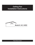
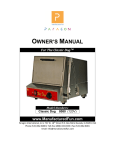
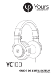
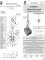
BT7819-888
mounting instructions
1
BT7819-888
mounting instructions
2
Assemble the ball-joint mount before installation on the pole.
28
11
35
Drill holes on the Ø50mm
(2”) pole.
*For the poles that are not supplied from
B-Tech.
3
Slide the collar and ball-joint onto the pole.
9
Ø10.5mm
1
2
10
Diagram A
Diagram B
Diagram C
Diagram D
Slide the collar on the ball-joint bracket (Diagram A). Insert the safety pin into the hole at the corner of the
collar, make sure that the safety pin is inserted through the ball-joint bracket (Diagram B). Use either the
finger screws for quick release and easy installation (Diagram C), or the security allen screws, to secure collar
position on the ball-joint bracket (Diagram D).
Drill Ø10.5mm hole horizontally straight through
the pole at the distance from the end of the pole to
the center of the hole.
Mount the legs on the projector.
4
5
4
20
18 19
17
Choose the correct legs for the projector:
24 23
1. Number of legs chosen depends
22 21
on the number of mounting holes on the
projector. (Where possible, use 4 legs).
2. The size of the legs depends on where
the carousel disc is placed. Mount the
carousel disc as close as possible to the
centre of gravity of the projector.
*The centre of the projector is not always the
centre of gravity, as the weight may be unevenly
distributed.
Please see Diagram H for your reference on the legs mounting.
3. Check the projector’s manual for screw sizes (M3, M4, M5 or M6).
If the projector has recessed holes, or has an uneven mounting surface,
then choose suitable spacers and/ or washers with spring washers to
allow for a level mounting. Do NOT overtighten.
7
8
Attach the cover plates over
the carousel disc.
27
25 26
29
5
Diagram H
3 mounting holes,
2 short legs and 1
long leg.
12
20mm (minimum distance
from the end of the pole to
the center of the hole)
4 mounting holes,
2 short legs and 2
long leg.
Adjust M8 hexagon bolt
9
34
Diagram E
Diagram F
Diagram G
Slide collar and ball-joint up onto the pole (Diagram E). Insert the safety bolt through the
retaining plate, collar and pole (Diagram F). Fasten brake screws into the thread holes to fix
the position of the collar (Diagram G).
Assemble carousel disc to
ball joint bracket.
Assemble carousel
disc to ball-joint
bracket, using the
square end allen
screw with spring
washer (Diagram I).
Once securely
3
attached, fasten
brake screw
into ball-joint arm
(Diagram J). (This
14
will stop carousel disc
from unnecessarily 15
16
rotating once
34
mount is installed).
Diagram I
13
33
Diagram J
6
Mount projector to the carousel disc.
Position the carousel
disc so that the legs
fit into the slots.
Use either the hand
wheels for easy access
to projector light blub
(Diagram K), or the
locking dome nuts
to secure leg position
on carousel disc
(Diagram L). Tighten
the screws, fixing the
legs to the projector.
32
6
31
Diagram K
Diagram L
Rotate the projector to desired position.
36
8
Diagram M
Adjust M8 hexagon bolt on the ball joint bracket to alter
the tension of the ball-joint. Make sure that the stiffness of
ball-joint can hold the projector in place after moving.
To complete installation attach the two halves of the
carousel cover plate over the carousel disc.
page 2
Diagram N
Diagram O
The Aviball arm allows the projector to move freely 37º in any direction (Diagram M) or to rotate 360º (Diagram N). To increase
stiffness of arm and to lock projector in position, use the spanner to make a small adjustment of the M8 bolt on the ball-joint bracket
(Diagram O).
page 3