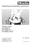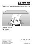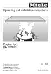
1
Operating and installation instructions
Cooker hood
DA 5390 W, DA 5320 W
To avoid the risk of accidents
or damage to this appliance
it is essential to read these
instructions before it is installed
and used for the first time.
en - GB, AU, NZ
M.-Nr. 07 260 270
Contents
Caring for the environment . . . . . . . . . . . . . . . . . . . . . . . . . . . . . . . . . . . . . . . . . . 3
Warning and Safety instructions . . . . . . . . . . . . . . . . . . . . . . . . . . . . . . . . . . . . . 4
Guide to the appliance . . . . . . . . . . . . . . . . . . . . . . . . . . . . . . . . . . . . . . . . . . . . 10
Mode of operation . . . . . . . . . . . . . . . . . . . . . . . . . . . . . . . . . . . . . . . . . . . . . . . . 12
Miele|home . . . . . . . . . . . . . . . . . . . . . . . . . . . . . . . . . . . . . . . . . . . . . . . . . . . . . 13
Con|ctivity . . . . . . . . . . . . . . . . . . . . . . . . . . . . . . . . . . . . . . . . . . . . . . . . . . . . . . 13
Operation . . . . . . . . . . . . . . . . . . . . . . . . . . . . . . . . . . . . . . . . . . . . . . . . . . . . . . . 14
To switch the fan on . . . . . . . . . . . . . . . . . . . . . . . . . . . . . . . . . . . . . . . . . . . . . . . . 14
To select a power level . . . . . . . . . . . . . . . . . . . . . . . . . . . . . . . . . . . . . . . . . . . . . 14
Run-on option . . . . . . . . . . . . . . . . . . . . . . . . . . . . . . . . . . . . . . . . . . . . . . . . . . . . 15
To switch the fan off . . . . . . . . . . . . . . . . . . . . . . . . . . . . . . . . . . . . . . . . . . . . . . . . 15
To switch the hob lighting on . . . . . . . . . . . . . . . . . . . . . . . . . . . . . . . . . . . . . . . . . 16
To dim the hob lighting . . . . . . . . . . . . . . . . . . . . . . . . . . . . . . . . . . . . . . . . . . . . . 16
To switch the hob lighting off . . . . . . . . . . . . . . . . . . . . . . . . . . . . . . . . . . . . . . . . . 16
Filter operating hours counter . . . . . . . . . . . . . . . . . . . . . . . . . . . . . . . . . . . . . . . . 17
Cleaning and care . . . . . . . . . . . . . . . . . . . . . . . . . . . . . . . . . . . . . . . . . . . . . . . . 19
Housing . . . . . . . . . . . . . . . . . . . . . . . . . . . . . . . . . . . . . . . . . . . . . . . . . . . . . . . . . 19
Grease filters . . . . . . . . . . . . . . . . . . . . . . . . . . . . . . . . . . . . . . . . . . . . . . . . . . . . . 20
Changing a halogen lamp . . . . . . . . . . . . . . . . . . . . . . . . . . . . . . . . . . . . . . . . . . . 22
After Sales Service . . . . . . . . . . . . . . . . . . . . . . . . . . . . . . . . . . . . . . . . . . . . . . . 23
Appliance dimensions . . . . . . . . . . . . . . . . . . . . . . . . . . . . . . . . . . . . . . . . . . . . . 24
Safety distance between hob and cooker hood (S) . . . . . . . . . . . . . . . . . . . . . 25
Installation . . . . . . . . . . . . . . . . . . . . . . . . . . . . . . . . . . . . . . . . . . . . . . . . . . . . . . 26
Assembly parts . . . . . . . . . . . . . . . . . . . . . . . . . . . . . . . . . . . . . . . . . . . . . . . . . . . 26
Installation instructions . . . . . . . . . . . . . . . . . . . . . . . . . . . . . . . . . . . . . . . . . . . . . 28
Protective foil . . . . . . . . . . . . . . . . . . . . . . . . . . . . . . . . . . . . . . . . . . . . . . . . . . . . . 28
Dismantling . . . . . . . . . . . . . . . . . . . . . . . . . . . . . . . . . . . . . . . . . . . . . . . . . . . . . . 28
Electrical connection . . . . . . . . . . . . . . . . . . . . . . . . . . . . . . . . . . . . . . . . . . . . . 29
Operation with Control module DSM 400 . . . . . . . . . . . . . . . . . . . . . . . . . . . . . 30
Connection to a window contact switch . . . . . . . . . . . . . . . . . . . . . . . . . . . . . . 30
Potential free connection . . . . . . . . . . . . . . . . . . . . . . . . . . . . . . . . . . . . . . . . . 30
Connection to a light switch . . . . . . . . . . . . . . . . . . . . . . . . . . . . . . . . . . . . . . . 31
Connection for air extraction . . . . . . . . . . . . . . . . . . . . . . . . . . . . . . . . . . . . . . . 32
Technical data . . . . . . . . . . . . . . . . . . . . . . . . . . . . . . . . . . . . . . . . . . . . . . . . . . . 34
2
Caring for the environment
Disposal of the packing
material
The transport and protective packing
has been selected from materials which
are environmentally friendly for
disposal, and can normally be
recycled.
Packaging e.g. cling film, polystyrene
and plastic wrappings must be kept out
of the reach of babies and young
children. Danger of suffocation!
Disposal of your old appliance
Electrical and electronic appliances
often contain materials which, if
handled or disposed of incorrectly,
could be potentially hazardous to
human health and to the environment.
They are, however, essential for the
correct functioning of your appliance.
Please do not therefore dispose of it
with your household waste.
Dispose of or recycle all packaging
materials safely as soon as possible.
Please dispose of it at your local
community waste collection / recycling
centre or contact your dealer for
advice. Ensure that it presents no
danger to children while being stored
for disposal.
It should be unplugged or disconnected
from the mains electricity supply by a
competent person.
3
Warning and Safety instructions
Safety with children
This appliance complies with all
relevant local and national safety
requirements. Inappropriate use
can, however, lead to personal injury
and damage to property.
To avoid the risk of accidents and
damage to the appliance, please
read these instructions carefully
before using it for the first time.
They contain important information
on the safety, installation, use and
maintenance of the appliance.
Keep these instructions in a safe
place and ensure that all users are
familiar with the contents. Pass them
on to any future owner of the
appliance.
Correct application
~ This appliance is intended for
domestic use only.
Any other usage is at the owner's risk
and could be dangerous. The
manufacturer cannot be held liable for
damage resulting from incorrect or
improper use or operation.
~ This appliance is not intended for
use by persons (including children)
with reduced physical, sensory or
mental capabilities, or lack of
experience or knowledge, unless they
are supervised whilst using it or have
been given instruction concerning its
use by a person responsible for their
safety.
4
~ This appliance is only intended for
use by adults who have read these
instructions.
~ This appliance is not a toy! To avoid
the risk of injury, keep children well
away and do not allow them to play with
it or to use the controls. They will not
understand the potential dangers
posed by it. They should be supervised
whenever you are working in the
kitchen.
~ Older children may use the cooker
hood only when its operation has been
clearly explained to them and they are
able to use it safely, recognising the
dangers of misuse.
~ Please be aware that on cooker
hoods with halogen lighting, the lamps
will get very hot during use and remain
hot for some time after switching off. To
safeguard against burning, keep
children well away from the lamps at all
times.
Technical safety
~ Before installation, check the cooker
hood for visible signs of damage.
Under no circumstances should you
use a damaged appliance. A damaged
appliance is dangerous.
Warning and Safety instructions
~ Before connecting the appliance to
the mains supply, make sure that the
voltage and frequency details given on
the data plate correspond with the
on-site electricity supply (see "After
Sales Service"). If they do not
correspond the appliance could suffer
damage. Consult a qualified electrician
if in any doubt.
~ Installation, maintenance and
~ The electrical safety of this
appliance can only be guaranteed
when continuity is complete between
the appliance and an effective earthing
system which complies with current
local and national safety regulations. It
is most important that this basic safety
requirement is present and tested
regularly, and where there is any doubt,
the household wiring system should be
inspected by a qualified electrician.
The manufacturer cannot be held liable
for the consequences of an inadequate
earthing system (e.g. electric shock).
~ Faulty components must only be
~ For safety reasons, this appliance
repairs may only be carried out by a
Miele authorised person in accordance
with current national and local safety
regulations.
Repairs and other work by unqualified
persons could be dangerous. The
manufacturer cannot be held liable for
unauthorised work.
replaced by genuine Miele original
parts. The manufacturer can only
guarantee the safety of the appliance
when Miele replacement parts are
used.
~ During installation, maintenance and
repair work, the appliance must be
disconnected from the mains electricity
supply. It is only completely isolated
from the electricity supply when:
– it is switched off at the isolator, or
– the screw-out fuse is removed (in
countries where this is applicable), or
may only be used when it has been
fully installed.
– the mains fuse is disconnected, or
~ Only open the housing as described
– it is switched off at the wall socket
and the plug withdrawn, or
in the instructions given in the
installation sheet and in the Cleaning
and care section of this booklet. Under
no circumstances should any other
parts of the housing be opened.
Tampering with electrical connections
or components and mechanical parts is
highly dangerous to the user, and can
cause operational faults.
– the fuse from the fused spur
connection unit is withdrawn.
5
Warning and Safety instructions
~ Do not connect the appliance to the
mains electricity supply by a
multi-socket unit or an extension lead.
These do not guarantee the required
safety of the appliance (e.g. danger of
overheating).
Using at the same time as other
heating appliances that depend on
the air from the room
Warning - danger of toxic fumes
~ This appliance may only be used in
mobile installations such as ships,
caravans, aircraft etc. if a risk
assessment of the installation has been
carried out by a suitably qualified
engineer.
~ In areas which may be subject to
infestation by cockroaches or other
vermin, pay particular attention to
keeping the appliance and its
surroundings in a clean condition at all
times. Any damage which may be
caused by cockroaches or other vermin
will not be covered by the guarantee.
~ Great care should be taken when
using the cooker hood at the same time
and in the same room or area of the
house as another heating appliance
which depends on the air in the room.
Such appliances include gas, oil, wood
or coal-fired boilers and heaters,
continuous flow or other water heaters,
gas hobs, cookers or ovens which draw
air in from the room and duct exhaust
gases out through a chimney or
extraction ducting.
When used in extraction mode, the
appliance draws air in from the room in
which it is installed and from
neighbouring rooms.
If there is insufficient air, an
underpressure will occur. The heating
appliance may be starved of oxygen,
impairing combustion.
Harmful gases could be drawn out of
the chimney or extraction ducting back
into the room, with potentially fatal
consequences.
6
Warning and Safety instructions
In order to ensure safe operation, and
to prevent gases given off by the
heating appliances from being drawn
back into the room when the cooker
hood and the heater are in operation
simultaneously, an underpressure of
0.04 mbar (4 pa) is the maximum
permissible in the room.
One of the following technical
measures may be necessary to ensure
safe operation.
– If the only way of ensuring adequate
ventilation is via an open window, a
window contact switch should be
fitted to ensure that the cooker hood
can only operate when the window is
opened sufficiently. A window
contact switch kit is available from
good builders' merchants.
Take care when ventilating the room
through an open window that
ventilation is not impaired by a
closed blind or curtain.
– The cooker hood can be set up to
automatically switch on an air intake
fan or open a motorised inlet flap
when it is switched on.
Ventilation can be maintained by air
inlets which must not be blocked, in
windows, doors and outside wall vents,
or by other technical measures, such
as ensuring that the cooker hood can
only be switched on when the heating
appliance is switched off or vice versa.
A ventilation brick alone is not generally
sufficient to ensure safe ventilation.
,The overall ventilation condition
of the dwelling must be taken into
account. If in doubt, the advice of a
competent builder or, for gas, a
qualified gas fitter (Corgi registered
in the UK) must be sought.
– The cooker hood can be set up to
automatically switch off a heating
appliance which also depends on
the air from the room when it is
switched on.
The Miele DSM 400 control module
offers the possibility of combining other
components with the cooker hood (see
"Operation with Control module DSM
400").
It is available to purchase as an
optional extra.
If in any doubt , the advice of a
qualified builder, gas fitter (Corgi
registered in the UK) or electrician
must be sought.
7
Warning and Safety instructions
Correct use
~ Never use an open flame beneath
the cooker hood. To avoid the danger
of fire, do not flambé or grill over an
open flame under the cooker hood.
When switched on, the cooker hood
could draw flames into the filter. Fat
particles drawn into the cooker hood
present a fire hazard.
~ Do not use the cooker hood without
the filters in place. This way you will
avoid the risk of grease and dirt getting
into the appliance and hindering its
smooth operation.
~ The filters should be regularly
cleaned or changed as appropriate.
Saturated filters are a fire hazard. See
"Cleaning and care".
~ When using the cooker hood over a
gas hob, ensure that any burners in use
are always covered by a pan. Switch
the cooking zone off when a pan is
removed, even for a short time.
Regulate the flame so that it does not
burn up the sides of the pan.
Do not allow the pans to overheat
excessively (e.g. when using a wok).
The cooker hood can become
damaged when exposed to excessive
heat.
~ Do not use a steam-cleaner to clean
~ Always switch the cooker hood on
between the top of the cooker or hob
and the bottom of the cooker hood
given in the "Appliance dimensions"
section of this booklet must be
maintained, unless the hob
manufacturer states that a greater
safety distance is required.
when a cooking zone is in use,
otherwise condensation may collect in
the hood, which could cause corrosion.
~ When cooking with oil or fat, chip
pans and deep fat fryers etc, do not
leave the pans unattended. Never leave
an open grill unattended when grilling.
Overheated oil and fat can ignite and
could set the cooker hood on fire.
8
this appliance. Pressurised steam
could reach the electrical components
and cause a short circuit.
Correct installation
~ Refer to the cooker or hob
manufacturer's instructions as to
whether a cooker hood may be
operated above the cooker/hob.
~ The minimum safety distances
If more than one appliance is fitted
beneath the cooker hood, and they
have different minimum safety
distances to the cooker hood, select
the greater distance.
Warning and Safety instructions
~ Safety regulations prohibit the fitting
of a cooker hood over solid fuel stoves.
~ All ducting, pipework and fittings
must be of non-flammable material.
These can be obtained from the Miele
Spare Parts department or from
builders' merchants.
~ The appliance must not be
connected to a chimney or vent flue
which is in use. Neither should it be
connected to ducting which ventilates
rooms with fireplaces.
~ If exhaust air is to be extracted into
a chimney or ventilation duct no longer
used for other purposes, seek
professional advice.
Accessories
~ Only use genuine Miele spare parts
and accessories with this appliance. If
spare parts or accessories from other
manufacturers are used, this will
invalidate the guarantee, and Miele
cannot accept liability.
The manufacturer cannot be held
liable for damage caused by
non-compliance with these Warning
and Safety instructions.
9
Guide to the appliance
10
Guide to the appliance
a Telescopic extension piece
h Touch control for the hob lighting
b Tower
This control switches the lighting on
and off, and is also a dimmer switch.
c Canopy
d Grease filters
e Decor panels Miele DDW 53x0
(optional accessory)
3 panels are required for the
DA 5390 W, and 4 panels for the
DA 5320 W.
f Control panel
g Hob lighting
i On/Off touch control for the fan
j Controls to select fan power level
k Touch control for the run-on
option
To activate the run-on option. The fan
can be set to continue running, and to
switch off automatically after either 5 or
15 minutes.
l Touch control for the
grease filters
The indicator lamp for the grease filters
lights up when the grease filters need
to be cleaned.
The touch control is used to reset the
operating hours counter every time the
grease filters are cleaned (see
"Cleaning and care").
It can also be used to check and alter
the operating hours counter.
For information about using the
appliance, see "Operation".
11
Mode of operation
The cooker hood works with
. . . air extraction:
The air is drawn in and cleaned by the
grease filters and directed outside.
The cooker hood is fitted with a
non-return flap which is closed when
the cooker hood is switched off. No
exchange of room and outside air can
take place.
When the cooker hood is switched on,
the non-return flap opens for the
cooking vapours to be blown directly
outside.
12
Miele|home
+
dai2385
Con|ctivity
+
This cooker hood is communication
enabled.
Communication module XKM 2000 DA
a, available as an optional extra,
enables the operation of the cooker
hood to be automatically controlled by
the operating status of a Miele electric
hob with onset controls.
For communication to take place, the
hob must be fitted with communication
module XKM 2000 KM b.
– When the hob is switched on the
cooker hood lights and the fan also
comes on.
– During cooking the cooker hood
automatically sets its power level
according to the number of cooking
zones in operation and their power
levels.
– After switching the hob off the fan
and the hob lighting will switch off
automatically after a period of time.
For detailed information about this
function please read the separate
instruction booklet supplied with the
XKM 2000 DA communication module.
The communication module is fitted to
the cooker hood in the area of the
motor and is connected to the controls
of the cooker hood.
This module must be installed by a
Miele service technician or suitably
qualified electrician.
The hob transmits information about its
operating status to the cooker hood via
the household power supply
(Powerline) c.
13
Operation
To switch the fan on
Automatic switch-off of the Intensive
setting
You can set the Intensive setting so that
it only runs for 10 minutes before
reverting automatically to level III.
^ Press the On/Off control.
The fan runs at power level "II".
The indicator lamp will come on.
If the cooker hood has been
connected to a window contact
switch via the DSM 400 control
module, then the fan cannot be
switched on if the window is shut.
The indicator lamp will flash.
^ To set this option, both the fan and
the hob lighting must be switched off.
^ Press the run-on option control for
approximately 10 seconds. The first
fan setting indicator will light up.
^ Then press in turn,
To select a power level
– the hob lighting control,
^ Use the – / + controls to select the
power level required.
+ control = higher setting
– control = lower setting
Depending on the intensity of cooking
vapours, levels "I" to "III" (green
indicator lamps) are usually sufficient
for normal cooking.
Intensive setting
When frying or cooking food with a
strong aroma, you may wish to select
the Intensive setting, level IV (yellow
indicator lamp) for a short period.
14
– the – control, and
– the hob lighting control again.
Operation
Run-on option
The indicator lamps for fan power levels
I and IV will flash if the automatic
switch-off for the Intensive setting is not
activated.
^ Press the + control to activate the
automatic switch-off.
The indicator lamps for fan power
levels I and IV will now light up
constantly.
Press the – control to deactivate the
automatic switch-off function.
It is advisable to leave the fan running
for a few minutes after cooking has
finished to neutralise any lingering
odours in the air.
The fan can be set to switch off
automatically after either 5 or 15
minutes:
^ After cooking has finished, press the
run-on option control whilst the fan is
still running.
– Press once = The fan will switch off
after 5 minutes (left-hand indicator
lamp).
^ Press the run-on option control to
confirm your selection.
If you do not confirm your selection
within 4 minutes, the cooker hood will
automatically revert to the original
setting.
– Press twice = The fan will switch off
after 15 minutes (right-hand indicator
lamp).
To switch off the run-on option, press
the run-on option control again. The
appliance will then not switch off
automatically.
To switch the fan off
^ Press the On/Off control to switch the
fan off.
The indicator lamp will go out.
15
Operation
To switch the hob lighting on
Safety cut-out
The hob lighting can be switched on
and off independently of the fan.
Should the cooker hood be left on, the
fan will switch off automatically after 10
hours. The lighting will remain on.
^ Briefly press the hob lighting control
to switch on the hob lighting.
The indicator lamp will come on.
The lighting will switch on at maximum
brightness.
To dim the hob lighting
The brightness of the lighting can be
adjusted.
^ With the lighting switched on, press
and hold the hob lighting control in.
The brightness will gradually dim until
you release the control.
^ Press the control in again to increase
the brightness to the level required,
and then release it.
If you keep the control pressed in, the
light will continually change between
bright and dim.
To switch the hob lighting off
^ Briefly press the hob lighting control
to switch the lighting off.
The indicator lamp will go out.
16
^ Pressing the On/Off control will
switch the fan back on again.
Operation
Filter operating hours counter
The number of hours the appliance has
been in operation is stored in memory.
The operating hours counter tells you
when the grease filters need to be
cleaned.
Resetting the operating hours
counter for the grease filters
After 30 hours of operation (or another
time if the operating hours counter has
been altered), the grease filter indicator
lamp will light up. The grease filters
must then be cleaned.
Reading the filter operating hours
counter
To check the percentage of time set
already used:
^ Press the On/Off control to switch the
fan on.
^ Press and hold the grease filter
control.
Afterwards, the filter operating hours
counter must be reset.
^ To do this, press and hold the grease
filter control in for approximately
3 seconds while the fan is switched
on.
The indicator lamp for the control will
go out.
One or more of the indicator lamps for
the – / + controls will flash.
The number of flashing lamps shows
the percentage of the operating time
which has already been used up.
1 lamp
2 lamps
3 lamps
4 lamps
= 25 %
= 50 %
= 75 %
= 100 %
The number of operating hours used
remains in the memory, even when the
appliance is switched off or there is a
power cut.
17
Operation
Altering the filter operating hours
counter
The filter operating hours counter is set
at 30 hours. This can be lengthened or
shortened to suit the type of cooking
you do. You can choose 20, 30, 40 or
50 hours
– Select a short time if you roast or fry
a lot.
The – / + indicator lamps show the time
which has been set:
1st lamp from the left = 20 hours
2nd lamp from the left = 30 hours
3rd lamp from the left = 40 hours
4th lamp from the left = 50 hours
– If you use very little fat for cooking,
select a longer time.
^ Use the – / + controls to select the
desired time.
– If you only cook occasionally we
recommend that you still select a
short time, because grease which
has built up gradually over a long
period of time will harden on the
grease filters and make cleaning
more difficult.
^ Press the On/Off control to switch the
fan off.
^ Press the run-on option control and
the grease filter control at the same
time.
The indicator lamp for the grease filter
control and one of the – / + indicator
lamps will flash.
18
^ Confirm the selection by pressing the
grease filter control.
All the indicator lamps will go out.
If you do not confirm your selection
within 4 minutes, the cooker hood will
automatically revert to the original
setting.
Cleaning and care
Before any cleaning or maintenance
work is carried out, disconnect the
cooker hood from the mains supply.
Ensure that:
– it is switched off at the
isolator, or
– it is switched off at the wall
socket and the plug
removed, or
– the fuse from the fused spur
connection unit is withdrawn, or
– the mains fuse is withdrawn, or
– the screw-out fuse is removed
(in countries where this is
applicable).
A range of Miele branded cleaning and
conditioning agents are available to
order through your Miele Dealer /
Chartered Agent, the Miele Spare Parts
Department, or via the internet on
www.miele-shop.com.
Housing
General notes
The surfaces and controls are
susceptible to scratches and
abrasions. Please observe the
following cleaning instructions.
^ All external surfaces and controls can
be cleaned using a Miele E-Cloth or
with warm water and a small amount
of washing-up liquid applied with a
well wrung-out soft sponge or cloth.
Do not use too much water when
cleaning the controls. Water could
penetrate into the electronics and
cause damage.
Do not use:
– cleaning agents containing soda,
acids, chlorides or solvents,
– abrasive cleaning agents e.g.
powder cleaners or cream cleaners,
and abrasive sponges, e.g. pot
scourers or sponges which have
been previously used with abrasive
cleaning agents. These will damage
the surface material.
Important for appliances with
stainless steel housing
(This infomation does not apply to the
controls).
Stainless steel surfaces can be cleaned
using the Miele E-Cloth, or with a
proprietary non-abrasive cleaning
agent designed specifically for use on
stainless steel.
To help prevent re-soiling, a
conditioning agent for stainless steel
can also be used. Follow the
manufacturer's instructions on the
packaging.
^ Wipe the surfaces dry using a soft
cloth.
19
Cleaning and care
Important for appliances with
lacquered housing
(special order finish)
It is very difficult to clean this type of
surface without causing minor marks to
the surface material. This can become
particularly noticeable with darker
colours and if there is halogen lighting
in the kitchen.
An oversaturated filter is a fire
hazard.
If decor panels are fitted as an optional
extra, these need to be removed first.
Controls
The controls may suffer
discolouration or damage if soiling is
left on them for too long.
Remove soiling straight away.
Observe the General notes on cleaning
earlier in this section.
^ To do this, disengage them from their
catches.
^ See the notes under "Housing" for
how to clean the decor panels. Like
the grease filters, they can be
cleaned in the dishwasher.
Do not use stainless steel cleaning
agents on the controls.
Grease filters
The re-usable metal grease filters in the
appliance remove solid particles
(grease, dust, etc.) from the kitchen
vapours, preventing soiling of the
cooker hood.
To avoid a build-up of grease, the
grease filters should be cleaned
regularly (at least every 3-4 weeks), but
always clean immediately the grease
filter indicator lamp comes on.
20
^ To take out the grease filters, release
the locking clip on the filter, lower the
filter 45°, unhook it at the back and
remove it.
To avoid damaging the filters or the
hob below, make sure you hold the
filters securely at all times when
handling them.
Cleaning and care
Cleaning the grease filters by hand
^ Clean the filters with a soft nylon
brush in a mild solution of hot water
and a small amount of washing-up
liquid.
Do not use undiluted washing up
liquid.
When removing the filters for cleaning,
also clean off any residues of oil or fat
from the now accessible housing to
prevent the risk of these catching fire.
When putting the grease filters back in
position, ensure that the locking clips
are facing down towards the hob.
Do not use:
– cleaning agents containing
descaling agents,
– powder cleaners, cream cleaners or
abrasive all-purpose cleaning
agents,
– oven sprays.
Cleaning the grease filters in the
dishwasher
^ Place the filters as upright as
possible in the lower basket, with the
short sides upright, and wash on a
65°C programme, ensuring the spray
arm is not obstructed. If a Miele
dishwasher is being used, select the
Sensor wash programme.
^ Use a mild dishwasher detergent.
Depending on the cleaning agent
used, cleaning the filters in a
dishwasher can cause permanent
discolouration to the surface.
However, this will not affect the
functioning of the filters in any way.
If a grease filter is inadvertently
replaced upside down, insert a small
screwdriver blade into the slit to
disengage the clip.
^ After replacing the grease filters,
press the grease filter control for
approximately 3 seconds to reset the
operating hours counter.
The indicator lamp will go out.
If the grease filters are cleaned before
the operating hours counter has
reached its maximum, the grease filter
control should be pressed for
approximately 6 seconds to reset the
counter.
^ After cleaning, leave the filters to dry
on an absorbent surface before
replacing them.
21
Cleaning and care
Changing a halogen lamp
^ Before any cleaning or maintenance
work, disconnect the cooker hood
from the mains supply. Ensure that–
– it is switched off at the isolator, or
– it is switched off at the wall socket
and the plug is withdrawn, or
– the fuse from the fused spur
connection unit is withdrawn, or
– the mains fuse is disconnected, or
– the screw-out fuse is removed (in
countries where this is applicable).
,Exercise caution when changing
halogen lamps. They get very hot
during use and remain hot for some
time after being switched off. Let
them cool down before you change
them.
Do not touch the surface directly
when changing a lamp, as grease
particles from your fingers will
adhere to the surface and damage
it. Please follow the manufacturer's
instructions.
22
^ To access the halogen lamp, push
the lamp cover gently upwards. The
cover will open and can be pulled
down.
^ Pull the old halogen lamp out of the
connection socket and replace it with
a new one (20 W, G 4 cap).
^ Push the cover back up and make
sure it clicks into place.
After Sales Service
In the event of a fault which you cannot
correct yourself, or if the appliance is
under guarantee, please contact:
– Your Miele Dealer / Chartered Agent
or
– The Miele Customer Contact Centre
(see back cover for address).
When contacting your Dealer or Miele,
please quote the model and serial
number of your appliance. These are
shown on the data plate which is visible
when the grease filter is removed.
For G.B.: Please note that telephone
calls may be monitored and
recorded for training purposes.
23
Appliance dimensions
DA 5390 W
DA 5320 W
24
Appliance dimensions
The shaded areas 1) and 2) represent
the wall or ceiling area for the vent
cut-out, for feeding the connection
cable through to an external fan and for
fitting the connection socket.
Connection for air extraction
C 200 mm
Safety distance between hob and
cooker hood (S)
When planning the installation height
of your cooker hood, the minimum
safety distance between the top of a
cooker or hob and the bottom of the
cooker hood are as follows, unless a
greater distance is specified by the
manufacturer of your cooking
appliance:
450 mm (GB), 600 mm (AU, NZ)
above electric hobs and cookers,
650 mm above an open grill
or deep fat fryer,
650 mm above gas hobs and
cookers.
If this cooker hood is installed above
a Miele Wok CS 1028 CombiSet
appliance, a minimum safety
distance of 760 mm must be
maintained between the burner and
the lower edge of the cooker hood.
– Account should also be taken of the
height of the person who will be
using the hood most often. The
person should have sufficient space
to work comfortably at the hob, and
also be able to reach the hood
controls with ease.
– If positioned too high, extraction will
be inefficient.
– If you want the top of the cooker
hood to be mounted flush with the
ceiling, make sure there is adequate
space below it for working. See
maximum/minimum appliance
height!
See "Warning and Safety"
instructions for further information.
25
Installation
Assembly parts
26
Installation
a 3 protective sheets
for use when fitting the tower.
b 2 hose clips
for securing the exhaust ducting.
c Telescopic wall bracket
for securing the cooker hood to the
wall.
2 screws 3.9 x 7.5 mm
for securing the tower.
1 hexagonal (Allen) key
for adjusting the height of the
appliance.
Installation instructions
1 lever
for dismantling the tower.
6 screws 5 x 40 mm and
6 x S 8 plugs for securing the bracket
to the wall.
The screws and plugs are designed
for use in solid walls only.
For other types of wall construction,
alternative fixings will be required.
Make sure that the wall is able to
take the weight of the cooker hood.
2 x M 6 self-tapping nuts
for securing the appliance.
27
Installation
Dismantling
Before installation, it is important to
read the information given on the
following pages as well as the
"Appliance dimensions" and the
"Warning and Safety instructions" at
the beginning of this book.
This is particularly crucial when
using the cooker hood at the same
time as a heating appliance that
relies on air from the same room, as
this could result in the build-up of
toxic fumes.
Should the appliance ever need to be
dismantled, follow the installation
instructions in reverse order as
described on the installation sheet.
A lever is supplied to assist with the
removal of the tower.
Installation instructions
See enclosed Installation sheet for
instructions on how to install this
appliance.
Protective foil
(on stainless steel appliances)
The housing components have
protective foil around them to prevent
them being damaged during transport.
Please remove this foil before fitting the
housing components. It can be peeled
off easily.
28
^ After loosening the fixing screws on
the tower, push the lever between the
tower and the extension piece to
lever the tower out of its fixings.
Electrical connection
All electrical work should be
undertaken by a suitably qualified
and competent person in strict
accordance with current national
and local safety regulations
(BS 7671 in the UK).
Installation, repairs and other work
by unqualified persons could be
dangerous, for which the
manufacturer cannot be held liable.
Ensure power is not supplied to the
appliance until after installation or
repair work has been carried out.
Do not connect the appliance to the
mains electricity supply by an
extension lead. These do not
guarantee the required safety of the
appliance.
The connection data is given on the
data plate. This is visible when the
grease filters have been removed.
Ensure that this data matches the
household mains supply.
If the switch is not accessible after
installation (depending on country), an
additional means of disconnection must
be provided for all poles.
For extra safety it is advisable to protect
the appliance with a suitable residual
current device (RCD). Contact a
qualified electrician for advice.
Important
This appliance is supplied for
connection to an a.c. 230 V single
phase 50 Hz supply.
The wires in the mains lead are
coloured in accordance with the
following code:
Green/yellow = earth
Blue
= neutral
Brown
= live
WARNING:
THIS APPLIANCE MUST BE
EARTHED
Connection of this appliance should be
made via a suitable isolator or a double
pole fused spur connection unit which
complies with national and local safety
regulations and the On-Off switch
should be easily accessible after the
appliance has been built in.
When switched off there must be an
all-pole contact gap of 3 mm in the
switch (including switch, fuses and
relays according to EN 60335).
29
Operation with Control module DSM 400
The Miele DSM 400 Control module can
be used to combine the cooker hood
with other components.
It enables the following:
Connection to a window contact
switch
If adequate ventilation to the room can
only be ensured by having a window
open when the cooker hood is in use at
the same time as a heating appliance
which depends on the air from the
same room, then the control module
can be used to connect a window
contact switch (not supplied) to the
appliance.
Once connnected, the cooker hood can
only be operated when the window is
sufficiently open (see also "Warning
and Safety instructions").
When the window is closed the cooker
hood fan cannot be switched on. The
indicator lamp for the On/Off touch
control on the cooker hood will flash.
The cooker hood lighting is not affected
by this.
Take care when ventilating the room
through an open window that ventilation
is not impaired by a closed blind or
curtain.
If the control module is disconnected
in order to operate the cooker hood
without the window contact switch
(e.g. after moving house) the cooker
hood electronics must be reset by a
Miele service technician.
Potential free connection
This enables an external appliance to
be controlled according to the switch
setting on the cooker hood fan.
– For instance it can be used to ensure
a sufficient supply of fresh air when
the cooker hood and a heating
appliance which also depends on
the air in the room are being used
together, by switching on an air
intake fan, or opening a motorised
inlet flap as soon as the cooker hood
fan is switched on. It is important to
ensure that the fan power is sufficient
and that the air intake has a suitable
cross-sectional diameter.
– If a sufficient air intake cannot be
guaranteed, then the potential free
contact will enable a heating
appliance, which depends on air in
the same room as a cooker hood, to
be switched off when the cooker
hood is in operation.
See also "Warning and Safety"
instructions.
30
Operation with Control module DSM 400
Connection to a light switch
The control module can be used to
switch on the cooker hood lighting and
also to dim it, depending on model, via
a light switch in the house.
Installation
The tower needs to be removed before
the control module can be fitted to the
fan unit.
The control module is supplied with its
own detailed operating and installation
instructions.
31
Connection for air extraction
,Important: To avoid the danger
of toxic fumes, please observe the
Warning and Safety instructions.
This is especially crucial when using
the cooker hood at the same time as
another heating appliance which
relies on air from the same room.
The cooker hood should be installed
according to local and national
building regulations. Seek approval
from the building inspector where
necessary.
If the exhaust ducting is secured to
the exhaust stub by a hose clip,
ensure that it is fitted correctly and is
not askew. Do not overtighten.
Otherwise the exhaust stub could
buckle and the non-return flap could
become jammed.
– All ducting, pipework and fittings
must be of non-flammable materials.
– The exhaust ducting should be as
short and straight as possible.
– To ensure efficient air extraction, the
diameter of the exhaust ducting
should not be less than 200 mm.
If exhaust ducting with a diameter of
less than 200 mm, or if flat ducting is
used, the noise level of the cooker
hood will increase and extraction will
be less efficient.
Only reduce the diameter of the
ducting if absolutely necessary, e.g.
where narrower ducting has already
been installed.
– Only use wide radius bends. Tight
bends reduce the air throughput of
the cooker hood.
– Only use smooth pipes or flexible
hoses made from non-flammable
materials for extraction connection.
32
– When ducting is horizontal it must be
laid to slope away at at least 1 cm
per metre to ensure no condensate
drains into the appliance.
– If the exhaust air is to be ducted into
a vent flue, the ducting must be
directed in the flow direction of the
flue.
Important
If the exhaust ducting is to run through
rooms, ceiling space etc. where there
may be great variations in temperature
between the different areas, the
problem of condensation will need to
be addressed. The exhaust ducting will
need to be suitably insulated.
Connection for air extraction
For exhaust ducting with a diameter of
200 mm, the following accessories are
required:
– Exhaust hose DAS 200
– Exhaust grille DFG 200, for mounting
on the external wall.
*Lead flashing
– Roof ducting DDF 200, for mounting
on a sloping tiled roof.
– Reducing collar for the exhaust stub
if using exhaust ducting with a 150
mm diameter.
33
Technical data
Total connected load
- DA 5390 W . . . . . . . . . . . . . . . . 580 W
- DA 5320 W . . . . . . . . . . . . . . . . 600 W
Fan. . . . . . . . . . . . . . . . . . . . . . . . 500 W
Hob lighting
- DA 5390 W . . . . . . . . . . . . . . 4 x 20 W
- DA 5320 W . . . . . . . . . . . . . . 5 x 20 W
Voltage . . . . . . . . . . . . . . . . . . . . 230 V
Frequency . . . . . . . . . . . . . . . . . . 50 Hz
Fuse rating GB . . . . . . . . . . . . . . . . 13 A
AUS, NZ:
Plug rating . . . . . . . . . . . . . . . . . . . 10 A
Test marks . . . . . . . . . . Electrical safety
. . . . . . . . . . . . . . . . . . . . . . C-Tick Mark
Electrical cable length . . . . . . . . . 1.5 m
Fan performance
Extraction power according to
EN 61591
Extraction system C 200 mm:
Level I . . . . . . . . . . . . . . . . . . . 350 m3/h
Level II. . . . . . . . . . . . . . . . . . . 600 m3/h
Level III . . . . . . . . . . . . . . . . . . 850 m3/h
Level IV Intensive Setting . . . 1,300 m3/h
Extraction system C 150 mm:
Level I . . . . . . . . . . . . . . . . . . . 300 m3/h
Level II. . . . . . . . . . . . . . . . . . . 500 m3/h
Level III . . . . . . . . . . . . . . . . . . 700 m3/h
Level IV Intensive Setting . . . 1,000 m3/h
Unrestricted . . . . . . . . . . . . . 1,450 m3/h
34
35
Alteration rights reserved / 4209
M.-Nr. 07 260 270 / 03