1
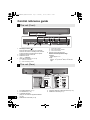
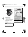
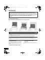
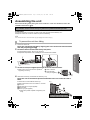
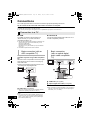
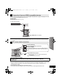
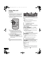
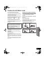
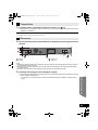
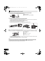
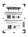
SCHTB10EGGNGS_RQTX1160-B.book Page 1 Thursday, June 10, 2010 3:14 PM Operating Instructions Home Theater Audio System Model No. SC-HTB10 Dear customer Thank you for purchasing this product. For optimum performance and safety, please read these instructions carefully. Before connecting, operating or adjusting this product, please read the instructions completely. Please keep this manual for future reference. The illustrations shown may differ from your unit. Included Installation Instructions The installation should never be done by any other than a qualified installation specialist. Before commencing work, carefully read these installation instructions and the operating instructions to ensure that installation is performed correctly. (Please keep these instructions. You may need them when maintaining or moving this unit.) RQTX1160-1B EG GN GS 2010/05/26 SCHTB10EGGNGS_RQTX1160-B.book Page 2 Monday, May 10, 2010 1:59 PM WARNING: TO REDUCE THE RISK OF FIRE, ELECTRIC SHOCK OR PRODUCT DAMAGE, ≥ DO NOT EXPOSE THIS APPARATUS TO RAIN, MOISTURE, DRIPPING OR SPLASHING AND THAT NO OBJECTS FILLED WITH LIQUIDS, SUCH AS VASES, SHALL BE PLACED ON THE APPARATUS. ≥ USE ONLY THE RECOMMENDED ACCESSORIES. ≥ DO NOT REMOVE THE COVER (OR BACK); THERE ARE NO USER SERVICEABLE PARTS INSIDE. REFER SERVICING TO QUALIFIED SERVICE PERSONNEL. CAUTION! ≥ DO NOT INSTALL OR PLACE THIS UNIT IN A BOOKCASE, BUILT-IN CABINET OR IN ANOTHER CONFINED SPACE. ENSURE THE UNIT IS WELL VENTILATED. TO PREVENT RISK OF ELECTRIC SHOCK OR FIRE HAZARD DUE TO OVERHEATING, ENSURE THAT CURTAINS AND ANY OTHER MATERIALS DO NOT OBSTRUCT THE VENTILATION VENTS. ≥ DO NOT OBSTRUCT THE UNIT’S VENTILATION OPENINGS WITH NEWSPAPERS, TABLECLOTHS, CURTAINS, AND SIMILAR ITEMS. ≥ DO NOT PLACE SOURCES OF NAKED FLAMES, SUCH AS LIGHTED CANDLES, ON THE UNIT. ≥ DISPOSE OF BATTERIES IN AN ENVIRONMENTALLY FRIENDLY MANNER. Warning Risk of fire, explosion and burns. Do not recharge, disassemble, heat above 60oC or incinerate. The socket outlet shall be installed near the equipment and easily accessible. The mains plug of the power supply cord shall remain readily operable. To completely disconnect this apparatus from the AC Mains, disconnect the power supply cord plug from AC receptacle. (Continental Europe, Australia and New Zealand) THIS UNIT IS INTENDED FOR USE IN MODERATE CLIMATES. (Others) THIS UNIT IS INTENDED FOR USE IN TROPICAL CLIMATES. This product may receive radio interference caused by mobile telephones during use. If such interference is apparent, please increase separation between the product and the mobile telephone. (For Asia and Africa) CAUTION: The AC voltage is different according to the area. Be sure to set the proper voltage in your area before use. (For details, please refer to page 11.) 2 SCHTB10EGGNGS_RQTX1160-B.book Page 3 Monday, May 10, 2010 1:59 PM Safety precautions Set the unit up on an even surface away from direct sunlight, high temperatures, high humidity, and excessive vibration. These conditions can damage the cabinet and other components, thereby shortening the unit’s service life. Do not place heavy items on the unit. Voltage Do not use high voltage power sources. This can overload the unit and cause a fire. Do not use a DC power source. Check the source carefully when setting the unit up on a ship or other places where DC is used. AC mains lead protection Ensure the AC mains lead is connected correctly and not damaged. Poor connection and lead damage can cause fire or electric shock. Do not pull, bend, or place heavy items on the lead. Grasp the plug firmly when unplugging the lead. Pulling the AC mains lead can cause electric shock. Do not handle the plug with wet hands. This can cause electric shock. Licenses Manufactured under license from Dolby Laboratories. Dolby, Pro Logic, and the double-D symbol are trademarks of Dolby Laboratories. Foreign matter Do not let metal objects fall inside the unit. This can cause electric shock or malfunction. Do not let liquids get into the unit. This can cause electric shock or malfunction. If this occurs, immediately disconnect the unit from the power supply and contact your dealer. Do not spray insecticides onto or into the unit. They contain flammable gases which can ignite if sprayed into the unit. Service Do not attempt to repair this unit by yourself. If sound is interrupted, indicators fail to light, smoke appears, or any other problem that is not covered in these instructions occurs, disconnect the AC mains lead and contact your dealer or an authorised service center. Electric shock or damage to the unit can occur if the unit is repaired, disassembled or reconstructed by unqualified persons. Extend operating life by disconnecting the unit from the power source if it is not to be used for a long time. Operating Instructions Placement Manufactured under license under U.S. Patent #’s: 5,451,942; 5,956,674; 5,974,380; 5,978,762; 6,487,535 & other U.S. and worldwide patents issued & pending. DTS and the Symbol are registered trademarks & DTS Digital Surround and the DTS logos are trademarks of DTS, Inc. Product includes software. © DTS, Inc. All Rights Reserved. HDMI, the HDMI Logo, and High-Definition Multimedia Interface are trademarks or registered trademarks of HDMI Licensing LLC in the United States and other countries. HDAVI Control™ is a trademark of Panasonic Corporation. 3 SCHTB10EGGNGS_RQTX1160-B.book Page 4 Monday, May 10, 2010 1:59 PM TABLE OF CONTENTS Operating Instructions Safety precautions ................................................................................................ 3 Licenses ................................................................................................................. 3 Accessories ........................................................................................................... 5 Unit care ................................................................................................................. 5 Control reference guide ........................................................................................ 6 This unit (Front) ..........................................................................................................................6 This unit (Rear) ..........................................................................................................................6 Remote control ...........................................................................................................................7 Placement .............................................................................................................. 8 Assembling the unit .............................................................................................. 9 Connections ........................................................................................................ 10 Connection to a TV ..................................................................................................................10 Connection from an HDMI compatible device ..........................................................................11 AC mains lead connection .......................................................................................................11 Using this unit ..................................................................................................... 12 Audio effects ....................................................................................................... 13 The various audio effects .........................................................................................................13 Changing the audio effects ......................................................................................................13 Linked operations with the TV (VIERA Link “HDAVI ControlTM”) ...................................................................... 14 Specifications ...................................................................................................... 15 Audio information ............................................................................................... 15 Troubleshooting .................................................................................................. 16 Remote control code ................................................................................................................17 Using the IR Blaster .................................................................................................................18 Caution for AC Mains Lead ................................................................................ 19 Installation Instructions Safety Precautions .............................................................................................. 20 Components ........................................................................................................ 22 Installation procedure ......................................................................................... 22 Attaching the wall mount brackets ...........................................................................................22 Connections .............................................................................................................................23 Placement ................................................................................................................................23 Attaching this unit to a wall ......................................................................................................24 4 SCHTB10EGGNGS_RQTX1160-B.book Page 5 Thursday, June 10, 2010 3:17 PM ≥ These operation instructions are applicable to model SC-HTB10 for variety of regions. ≥ Unless otherwise indicated, illustrations in these operating instructions are of the model for Continental Europe, Australia and New Zealand. ≥ Operations in these instructions are described mainly with the remote control, but you can perform the operations on this unit if the controls are the same. ≥ Some accessories and external devices mentioned in these operating instructions that are not supplied with this product may not be for sale in certain regions. Accessories Check the supplied accessories before using this unit. ∏ 1 Remote control (Built-in battery) ∏ 2 Wall mount brackets ∏ 2 Screws (N2QAYC000027) ∏ 2 Lock pins (Saudi Arabia and Kuwait) ∏ (Others) 1 IR Blaster ≥ Product numbers correct as of April 2010. These may be subject to change. Operating Instructions AC mains lead (Australia and New Zealand) ∏ Unit care ∫ Clean this unit with a soft, dry cloth ≥Never use alcohol, paint thinner or benzine to clean this unit. ≥Before using chemically treated cloth, carefully read the instructions that came with the cloth. ∫ To dispose or transfer this unit If you discard this unit either by disposal or transfer, then follow the procedure to return all the settings to the factory presets to delete the user settings. (> 16, “To return to the factory preset.”) 5 SCHTB10EGGNGS_RQTX1160-B.book Page 6 Thursday, June 10, 2010 3:17 PM Control reference guide This unit (Front) 1 1 2 3 4 2 3 4 Standby/on switch (Í/I) Press to switch the unit from on to standby mode or vice versa. In standby mode, the unit is still consuming a small amount of power. Adjust the Volume of this unit Select the source “TV” !# “BD/DVD” LED status indicators (> 12, 13) A B C D E 5 5 Sound Effect indicator Dolby Virtual Speaker indicator Audio format indicator Remote control signal sensor Remote control operation range Distance: Within approx. 7 m Angle: Approx. 10o up and 30o down, 30o left and right Audio source indicator Clear-mode Dialog indicator This unit (Rear) (For Asia and Africa) VOLT ADJ 220−240V 5 1 110−127V 2 AC IN 1 2 3 6 4 AC Voltage selector (> 11) AC IN terminal (> 11) Ir SYSTEM terminal (Only for use with the supplied IR Blaster. (> 18)) HDMI AV OUT terminal (> 10) 5 6 3 4 6 OPTICAL DIGITAL AUDIO IN terminal (> 10) HDMI AV IN terminal (> 11) SCHTB10EGGNGS_RQTX1160-B.book Page 7 Monday, May 10, 2010 1:59 PM Remote control Remove the insulation sheet A before using. 1 2 4 5 ∫ To replace a button-type battery 3 1 2 3 4 5 6 7 8 7 8 Turn this unit on or off (> 12) Select the source (> 12) [TV]: Select the TV as the source [BD/DVD]: Select the device connected to the HDMI AV IN terminal as the source Turn Clear-mode Dialog on or off (> 13) Adjust the Subwoofer level of this unit Adjust the Volume of this unit Mute the sound Turn Dolby Virtual Speaker on or off (> 13) Turn Sound Effect on or off (> 13) 1 While pressing the stopper B, pull out the battery holder. 2 Set the button-type battery with its (i) mark facing upward and then put the battery holder back in place. ≥ When the button-type battery runs down, replace it with a new battery (part number: CR2025). The battery should normally last about 1 year, however this depends on how frequently the unit is used. ≥ Do not heat or expose to flame. ≥ Do not leave the battery(ies) in an automobile exposed to direct sunlight for a long period of time with doors and windows closed. Warning Keep the Button-Type battery out of the reach of children. Never put Button-Type battery in mouth. If swallowed call your doctor. Operating Instructions 6 CAUTION Danger of explosion if battery is incorrectly replaced. Replace only with the same or equivalent type recommended by the manufacturer. Dispose of used batteries according to the manufacturer’s instructions. 7 SCHTB10EGGNGS_RQTX1160-B.book Page 8 Monday, May 10, 2010 1:59 PM Placement Caution ≥ This unit and the supplied wall mount brackets are to be used only as indicated in these operating instructions or the installation instructions. Failure to do so may lead to damage to the amplifier and/or the speakers, and may result in the risk of fire. Consult a qualified service person if damage has occurred or if you experience a sudden change in performance. ≥ Do not attempt to attach this unit to a wall using methods other than those described in this manual. How you place this unit can affect the bass and the sound field. Place this unit near the TV. This unit should be placed parallel to the seating position. E.g., On the wall In a rack§1, 2, 3 On a table§1, 2, 3, 4, 5 To attach this unit to the wall, refer to the installation instructions. (> 20) Installation work should never be done by any other than a qualified installation specialist. §1 Place this unit on a flat secure base. (Do not place this unit on the TV’s pedestal.) §2 To allow for proper ventilation and to allow for proper air flow around this unit, position it with at least 5 mm of space on all sides of this unit. §3 Secure the unit to prevent it from falling. (> 9) §4 Do not place this unit in front of a 3D compatible TV. This unit may block the transmitter for the 3D eyewear. §5 Do not place this unit too close to the TV. This unit may interfere with the TV’s various sensors (ambient light, etc.). ≥ You can damage the speakers and shorten their useful life if you play sound at high levels over extended periods. ≥ Placing this unit too close to the floor, walls, and corners can result in excessive bass. Cover walls and windows with thick curtains. ∫ If the TV’s remote control sensor is blocked by this unit. Try using the TV’s remote control from a different angle. If the problem persists, you can use the supplied IR Blaster to relay the signal to the TV. (> 18) ≥ Do not use the IR Blaster if the TV’s remote control sensor is not blocked by this unit. 8 ∫ If irregular colouring occurs on your TV, turn the TV off for about 30 minutes. If it persists, move this unit further away from the TV. SCHTB10EGGNGS_RQTX1160-B.book Page 9 Monday, May 10, 2010 1:59 PM Assembling the unit Refer to the following when placing this unit on a table or in a rack. For wall mount, refer to the installation instructions. (> 20) Professional installation is required. The installation should never be done by any other than a qualified installation specialist. Preparation ≥To prevent damage or scratches, lay down a soft cloth and perform the assembly on it. ≥Keep the screws out of reach of children to prevent swallowing. ≥ Do not hold this unit in one hand to avoid injury by dropping this unit when carrying. To prevent the unit from falling 1 2 On the rear of the unit: Place the wall mount bracket by aligning the holes in the wall mount bracket with the projecting parts A. Screw the wall mount bracket firmly into place. Operating Instructions ≥ Screw tightening torque: 80 N0cm to 120 N0cm. ≥ Repeat the steps above when installing the second wall mount bracket. 3 Thread a cord (not supplied) through each wall mount bracket. ≥ Make sure to use a cord which is capable of supporting over 20 kg. 4 A Rear of this unit B Fall prevention cord (not supplied) After all the necessary connections are finished (> 10) Place the unit in the desired position and attach each cord onto the rack or table. ≥ Attach each cord to a different screw eye. ≥ Make sure that there is no more than a 3 cm slack. A This unit B Fall prevention cord (not supplied) C Rack or table D Screw eye (not supplied) ≥ Attach at a position capable of supporting over 20 kg. E.g., 9 SCHTB10EGGNGS_RQTX1160-B.book Page 10 Monday, May 10, 2010 1:59 PM Connections Turn off all equipment before connection and read the appropriate operating instructions. Do not connect the AC mains lead until all other connections are complete. Compatible with FULL HD 3D TV and Blu-ray Player ≥ This unit can pass through the 3D signal from a 3D compatible Blu-ray Player to a FULL HD 3D TV. Connection to a TV ∫ HDMI ∫ OPTICAL IN The HDMI connection supports VIERA Link “HDAVI Control” (> 14) when used with a compatible Panasonic TV. Connect the optical digital audio cable if the TV is not ARC compatible (> below). ≥ Use High Speed HDMI Cables that have the HDMI logo (as shown on the cover). It is recommended that you use Panasonic’s HDMI cable. Recommended part number: RP-CDHS15 (1.5 m), RP-CDHS30 (3.0 m), RP-CDHS50 (5.0 m), etc. ≥ Non-HDMI-compliant cables cannot be utilised. Basic connection (with an ARC compatible TV) ARC (Audio Return Channel) (Available only when using an ARC compatible TV) With this function it is possible to receive the digital audio signal from the TV without connecting any other audio cable. ≥ Refer to the operating instructions of the TV for the settings to output digital audio. TV Basic connection (with an optical digital audio cable compatible TV) TV AV IN (ARC) OPTICAL OUT AV IN HDMI AV OUT OPTICAL DIGITAL AUDIO IN HDMI AV OUT (ARC) A HDMI cable (not supplied) B Optical digital audio cable (not supplied) A HDMI cable (not supplied) § Be sure to connect to the TV’s ARC compatible terminal. (Refer to the operating instructions for the TV.) 10 ≥ If the connected TV is ARC compatible, but audio is not output to this unit, connect using the optical digital audio cable. (> right, “Basic connection (with an optical digital audio cable compatible TV)”) ≥ When connected to an ARC compatible TV, set “TV Audio” to “ARC Off” to output the audio signal from the optical digital audio cable. (> 17, “TV Audio”) SCHTB10EGGNGS_RQTX1160-B.book Page 11 Thursday, June 10, 2010 3:18 PM Connection from an HDMI compatible device You can output the audio signal from the connected HDMI compatible Blu-ray player, DVD player, etc. with this unit and pass the signal through to your TV. Preparation ≥Connect this unit to the TV. (> 10) E.g., Blu-ray Disc Player AV OUT HDMI AV IN ≥ Refer to the operating instructions of the connected HDMI compatible device for the necessary setting, to output the video and audio signals. AC mains lead connection (For Asia and Africa) Before connecting the AC mains lead VOLT ADJ 220−240V Set the voltage. Use a flat-head screwdriver to move the voltage selector to the appropriate position for the area in which this system is used. 110−127V AC IN Operating Instructions A HDMI cable (not supplied) A AC mains lead (supplied) ≥Do not use any other AC mains lead except the supplied one. B To a household mains socket (For Saudi Arabia and Kuwait) BE SURE TO READ THE CAUTION FOR THE AC MAINS LEAD ON PAGE 19 BEFORE CONNECTION. ≥Connect only after all other connections are complete. ≥This unit consumes a small amount of AC power, even when it is in standby mode (approx. 0.2 W). In the interest of power conservation, if you will not be using this unit for a long time, unplug it from the household mains socket. ≥The supplied AC mains lead is for use with this unit only. Do not use it with other equipment. Also, do not use cords for other equipment with this unit. 11 SCHTB10EGGNGS_RQTX1160-B.book Page 12 Monday, May 10, 2010 1:59 PM Using this unit Preparation ≥ Turn on the TV. ≥ If VIERA Link is activated on both the connected TV and this unit, make sure to change the TV’s settings for this unit. (> 14, “Linked operations with the TV (VIERA Link “HDAVI ControlTM”)”) ≥ If VIERA Link is not activated or if the TV is not compatible with VIERA Link, reduce the volume of the TV to its minimum. 1 2 A B C Audio source indicator A The selected audio source is indicated Green: When the TV is the audio source Red: When the device connected to the HDMI AV IN terminal is the audio source To adjust the volume/ subwoofer level Press [i VOL j] to adjust the volume of the speakers. Press [i SUBWOOFER j] to adjust the subwoofer level. 1 Press [Í] to turn on this unit. ≥ The current status (audio source, active audio effects and audio format) is displayed. The audio effects and audio format indicator will turn off after 4 sec. 2 Press [TV] or [BD/DVD] to select the audio source. (> right) ≥ If you have selected [BD/DVD], make sure to select the TV’s input channel for this unit and start the playback. B The indicators blink from left to right (i) or from right to left (s). ≥ The indicators will not blink when it has reached the maximum or minimum. To mute the sound Press [MUTE]. B The indicators blink simultaneously while muting. ≥ To cancel, press the button again or adjust the volume. ≥ Muting is cancelled if this unit is turned off. Audio format indicator ≥ Before turning off this unit, be sure to reduce the volume. ≥ Even if this unit is turned off, the device connected to the HDMI AV IN terminal will continue to output audio or video to the TV. Press [ format. VS] to indicate the audio C The current audio format is indicated for 4 sec. Green: Dolby Digital Red: DTS Off: PCM or LPCM 12 ≥ The audio format status is also indicated for 4 sec if the audio format on the selected source (TV, Blu-ray Disc/DVD Player, etc.) is changed. ≥ The Dolby Virtual Speaker ( VS) audio effect status is also indicated. (> 13) SCHTB10EGGNGS_RQTX1160-B.book Page 13 Monday, May 10, 2010 1:59 PM Audio effects B C A The various audio effects Clear-mode Dialog You can make the dialogue stand out from the background noise and also hear sound as if it is coming from the centre of the TV. Sound Effect C Changing the audio effects 1 Press the button for the respective effect on the remote control. A: Clear-mode Dialog B: Sound Effect C: Dolby Virtual Speaker ( 2 Dolby Virtual Speaker 3 VS) The status of the selected effect is indicated for 4 sec. A: Clear-mode Dialog B: Sound Effect C: Dolby Virtual Speaker ( On: The indicator lights Off: The indicator blinks You can enjoy a dynamic sound with a natural expansion. You can enjoy a surround sound effect similar to 5.1 ch (Dolby Digital or DTS) with any audio source. B VS) While the indicator is lit or blinking, press the same button again to change the setting. Operating Instructions A ≥ When turning the audio effects on or off, there might be a slight pause in the audio. This is normal. ≥ Dolby Virtual Speaker ( VS) is also turned on when Sound Effect is turned on. (It will remain on even after Sound Effect is turned off.) ≥ If Dolby Virtual Speaker ( VS) is turned off while Sound Effect is on, the Sound Effect will also be turned off. ≥ The audio format is also indicated when [ VS] is pressed. (> 12) 13 SCHTB10EGGNGS_RQTX1160-B.book Page 14 Monday, May 10, 2010 1:59 PM Linked operations with the TV (VIERA Link “HDAVI ControlTM”) What is VIERA Link “HDAVI Control”? VIERA Link “HDAVI Control” is a convenient function that offers linked operations of this unit, and a Panasonic TV (VIERA) under “HDAVI Control”. You can use this function by connecting the equipment with an HDMI cable. See the operating instructions for connected equipment for operational details. Preparation 1 Set “VIERA Link” to “On”. (The default setting is “On”.) 2 Set the “HDAVI Control” operations on the connected equipment (e.g., TV). 3 For the optimal “HDAVI Control” operations change the following settings on the connected TV§1. ≥ Set the default speaker settings to this unit.§2 ≥ Set the speaker selection settings to this unit. ≥ Set the digital audio output settings to be compatible with this unit. (> 15) 4 Turn on all “HDAVI Control” compatible equipment and select this unit’s input channel on the connected TV so that the “HDAVI Control” function works properly. 5 Start playback on the device connected to the HDMI AV IN terminal and check that the image is displayed correctly. When the connection or settings are changed, repeat this procedure. §1 The availability and function of the settings may vary depending on the TV. Refer to the operating instructions for the TV for details. §2 If the TV has a default speaker setting within the VIERA Link setting items, choosing this unit as the default speaker will automatically change the speaker selection to this unit. Speaker Selection You can select whether audio output is from this unit or the TV speakers by using the TV menu settings. Home Cinema This unit’s speakers are active. ≥ When this unit is in standby mode, changing the TV speakers to this unit in the TV menu will automatically turn this unit on and select “TV” as the source. ≥ You can control the volume setting using the Volume or Mute button on the TV remote control. ≥ If you turn off this unit, TV speakers will be automatically activated. TV TV speakers are active. ≥ The volume of this unit is set to its minimum. ≥ When switching between this unit’s speakers and TV speakers, the TV screen may be blank for several seconds. Automatic input switching When the following operations are performed, this unit will automatically turn on§ and change the input channel to the corresponding source. jWhen play starts on an HDMI connected device. jWhen the input channel on the TV is changed. § Only when speaker output is set to this unit. ≥ If “Power off link” is activated on the TV, this unit will turn off when the TV is turned off. Automatic lip-sync function ≥ VIERA Link “HDAVI Control”, based on the control functions provided by HDMI which is an industry standard known as HDMI CEC (Consumer Electronics Control), is a unique function that we have developed and added. As such, its operation with other manufacturers’ equipment that supports HDMI CEC cannot be guaranteed. ≥ This unit supports “HDAVI Control 5” function. “HDAVI Control 5” is the newest standard (current as of December, 2009) for Panasonic’s HDAVI Control compatible equipment. This standard is compatible with Panasonic’s conventional HDAVI equipment. ≥ Please refer to individual manuals for other manufacturers’ equipment supporting VIERA Link function. 14 (for HDAVI Control 3 or later) Delay between audio and video is automatically adjusted, enabling you to enjoy smooth audio for the picture. ≥ The delay information is automatically set if the TV is compatible to VIERA Link “HDAVI Control 3 or later” and the VIERA Link is set to “On”. When the delay information cannot be retrieved, the audio delay is set to 40 ms. SCHTB10EGGNGS_RQTX1160-B.book Page 15 Monday, May 10, 2010 1:59 PM Specifications GENERAL SPEAKER SECTION 30 W Power consumption in standby mode: Approx. 0.2 W Power supply: (Continental Europe, Australia and New Zealand) FRONT SPEAKERS (BUILT-IN) Type: 1 way, 1 speaker system (Bass Reflex) Full range: 6.5 cm Cone typek2 SUBWOOFER (BUILT-IN) Type: 1 way, 1 speaker system (Bass Reflex)k2 Woofer: 8 cm Cone typek2 TERMINAL SECTION AC 220 V to 240 V, 50 Hz (Others) AC 110 V to 127 V/220 V to 240 V, 50/60 Hz Dimensions (WkHkD): (Without wall mount bracket) 800 mmk108 mmk58 mm (With wall mount bracket) 800 mmk108 mmk80 mm Mass: (Without wall mount bracket) Approx. 3.2 kg (With wall mount bracket) Approx. 3.3 kg Operating temperature range: 0 oC to r40 oC Operating humidity range: 20 % to 80 % RH (no condensation) AMPLIFIER SECTION RMS Output Power Front ch: 30 W per channel (4 ≠), 1 kHz, 10 % THD Subwoofer ch: 30 W per channel (4 ≠), 100 Hz, 10 % THD Total RMS Dolby Digital mode power: 120 W (Except Continental Europe, Australia and New Zealand) PMPO Output Power: 980 W HDMI This unit supports “HDAVI Control 5” function. HDMI input Input connector: Type A (19 pin) HDMI AV output Output connector: Type A (19 pin) Digital Audio Input (TV only) Optical digital input: Optical terminal Sampling frequency: 32 kHz, 44.1 kHz, 48 kHz Audio Format: LPCM, Dolby Digital IR Blaster Terminal 1: 3.5 mm jack 1 Specifications are subject to change without notice. Mass and dimensions are approximate. 2 Total harmonic distortion is measured by a digital spectrum analyzer. Audio information ∫ Compatible audio formats This unit is compatible with the following formats: Dolby Digital, DTS Digital Surround, 2-channel LPCM and multi-channel LPCM. ≥ When using the optical digital audio cable, this system is not able to play audio with a sampling frequency greater than 48 kHz. (Sound Effect and Dolby Virtual Speaker will be automatically cancelled if the audio signal’s sampling frequency is greater than 48 kHz.) Operating Instructions Power consumption: 15 SCHTB10EGGNGS_RQTX1160-B.book Page 16 Thursday, June 10, 2010 3:18 PM Troubleshooting Before requesting service, make the following checks. If you are in doubt about some of the check points, or if the solutions indicated in the following guide do not solve the problem, consult your dealer for instructions. General operation To return to the factory preset. ≥ While this unit is on, press [Í/I] on this unit for more than 4 sec. (All the indicators will blink twice when the unit is reset.) The remote control doesn’t work properly. ≥ It is possible that the insulation sheet has not been removed. Remove the insulation sheet. (> 7) ≥ The remote control and this unit are using different codes. Change the code on the remote control. (> 17) ≥ It may be necessary to set the code of the remote control again after changing the battery of the remote control. (> 17) This unit does not operate correctly. ≥ If the HDMI cable is connected to the wrong terminal (HDMI AV IN or HDMI AV OUT), this unit will not operate correctly. Turn this unit off, disconnect the AC mains lead and reconnect the HDMI cable(s). (> 10) Sound No sound (or image). ≥ Turn muting off. (> 12) ≥ Check the connections to the other devices. (> 10) ≥ Check the audio output settings on the connected device. ≥ Turn this unit off and then on again. ≥ When connected to an ARC compatible TV, check if the TV’s connected terminal is ARC compatible. ≥ If the connections are correct, there might be a problem with the cables. Reconnect the unit with different cables. ≥ When using the optical digital audio cable, this system is not able to play audio with a sampling frequency greater than 48 kHz. When operating the connected device, this unit reacts in an unwanted manner. ≥ HDAVI Control commands may use a different signal depending on the make of the device. In this case, set “VIERA Link” to “Off”. (> 17, “VIERA Link”) Sound is not heard when playing DVD-Audio. ≥ This may occur due to digital copyright protection of the disc when using the optical digital audio cable. This system is not able to play audio with a sampling frequency greater than 48 kHz. VIERA Link related operations no longer function properly. ≥ Check the “VIERA Link” setting on the connected devices. ≥ When the HDMI connections are changed, after a power failure or after the AC mains lead has been removed, VIERA Link operations may not function properly. If the “ D/DTS” indicator is blinking, unplug the AC mains lead and consult your dealer. Power 16 Power of this unit is turned off when the input for the TV is changed. ≥ This is a normal feature when using VIERA Link (HDAVI Control 4 or later). For details please read the operating instructions for the TV. No power. ≥ Insert the AC mains lead securely. (> 11) ≥ After turning this unit on, if the “TV, BD/DVD” indicator or the “ D/DTS” indicator blinks and this unit immediately turns off, unplug the AC mains lead and consult your dealer. If the “TV, BD/DVD” indicator is blinking, try the following to correct the problem. Consult your dealer if the problem persists. ≥ Turn the connected device off and on again. ≥ Turn this unit off and reconnect the HDMI cables and then turn this unit on again. Page 17 Thursday, June 10, 2010 If this unit is connected to a non-Panasonic ARC compatible TV, connect using an optical digital audio cable. (> 10) ≥ After connecting the optical digital audio cable, the setting of this unit must be changed to specify the audio input terminal. (> right, “TV Audio”) Audio is output from the TV speakers and not this unit’s. ≥ When connected to a VIERA Link (HDAVI Control) compatible TV, change the audio output settings to this unit. (> 14) Both main and secondary audio are output simultaneously. ≥ Change the digital audio output setting on the TV or connected device and then select the desired audio channel. (For details, refer to the operating instructions for the TV or connected device.) Changing this unit’s settings Refer to “Troubleshooting” (> 16) before changing any of the following settings. The settings remain intact even if you switch the unit to standby mode. A will blink green once when the setting is changed. A 3:19 PM Set “VIERA Link” to “On”. Press and hold [INPUT SELECTOR] on this unit and [SOUND EFFECT] on the remote control for more than 2 sec. ∫ TV Audio Set “TV Audio” to “ARC Off”. Set “TV Audio” to “ARC Off” only when using an optical digital audio cable with an ARC compatible TV. (> 16, “Sound”) Press and hold [INPUT SELECTOR] on this unit and [TV] on the remote control for more than 2 sec. Set “TV Audio” to “Auto”. Press and hold [INPUT SELECTOR] on this unit and [CLEAR-MODE DIALOG] on the remote control for more than 2 sec. Remote control code When other Panasonic products respond to this unit’s remote control, change the remote control code on this unit and the remote control. Preparation ≥ Turn off all other Panasonic products. ≥ Turn on this unit. Change the remote control to code 2: 1 Aim the remote control at this unit’s remote control sensor. 2 Press and hold [CLEAR-MODE DIALOG] and [BD/DVD] on the remote control for more than 4 sec. A Operating Instructions SCHTB10EGGNGS_RQTX1160-B.book ∫ VIERA Link Changes to this setting become effective after turning off and on all the connected devices. Set “VIERA Link” to “Off”. Set “VIERA Link” to “Off” when you do not want to use “HDAVI Control”. (> 16, “General operation”) Press and hold [INPUT SELECTOR] on this unit and [BD/DVD] on the remote control for more than 2 sec. ≥ When set to “Off”, the ARC function is not available. Be sure to connect using the optical digital audio cable. (> 10) A will blink green once when the code of this unit is changed. ≥ If the unit does not operate after changing the code, repeat steps 1 and 2. ≥ To change the remote control to code 1, repeat the steps above, but replace [BD/DVD] with [TV]. 17 SCHTB10EGGNGS_RQTX1160-B.book Page 18 Monday, May 10, 2010 1:59 PM Using the IR Blaster With the IR Blaster connection, it is possible to send the IR signal received by this unit’s remote control signal sensor to the TV’s sensor. Use the TV’s remote control within this unit’s remote control signal sensor’s operation range. ≥For the operation range, refer to page 6. 1 Connect the jack plug to this unit’s Ir SYSTEM terminal. 2 Place the infrared emitter in sight of the TV’s remote control signal sensor. Ir SYSTEM ≥ For the location of the TV’s remote control signal sensor, refer to the operating instructions for the TV. 3 Aim the TV’s remote control at this unit’s remote control sensor and operate the TV. ≥ For the location of this unit’s remote control signal sensor, refer A Infrared emitter to page 6. ≥ Make sure to clean the surface, where the adhesive tape is to be attached. ≥ If you peel off the adhesive tape, the surface may become damaged and exposed adhesive may remain. Once you have confirmed the TV is operating correctly, secure it by attaching the adhesive tape. ≥ The supplied IR Blaster is only compatible with Panasonic TVs. ∫ Placement example On the rear of this unit: TV remote control signal sensor Adhesive tape 18 SCHTB10EGGNGS_RQTX1160-B.book Page 19 Monday, May 10, 2010 1:59 PM Caution for AC Mains Lead For your safety, please read the following text carefully. This appliance is supplied with a moulded three pin mains plug for your safety and convenience. A 5-ampere fuse is fitted in this plug. Should the fuse need to be replaced please ensure that the replacement fuse has a rating of 5-ampere and that it is approved by ASTA or BSI to BS1362. Check for the ASTA mark Ï or the BSI mark Ì on the body of the fuse. If the plug contains a removable fuse cover you must ensure that it is refitted when the fuse is replaced. If you lose the fuse cover the plug must not be used until a replacement cover is obtained. A replacement fuse cover can be purchased from your local dealer. CAUTION! IF THE FITTED MOULDED PLUG IS UNSUITABLE FOR THE SOCKET OUTLET IN YOUR HOME THEN THE FUSE SHOULD BE REMOVED AND THE PLUG CUT OFF AND DISPOSED OF SAFELY. THERE IS A DANGER OF SEVERE ELECTRICAL SHOCK IF THE CUT OFF PLUG IS INSERTED INTO ANY 13-AMPERE SOCKET. If a new plug is to be fitted please observe the wiring code as stated below. If in any doubt please consult a qualified electrician. IMPORTANT The wires in this mains lead are coloured in accordance with the following code: Blue: Neutral, Brown: Live. As these colours may not correspond with the coloured markings identifying the terminals in your plug, proceed as follows: The wire which is coloured Blue must be connected to the terminal which is marked with the letter N or coloured Black or Blue. The wire which is coloured Brown must be connected to the terminal which is marked with the letter L or coloured Brown or Red. WARNING: DO NOT CONNECT EITHER WIRE TO THE EARTH TERMINAL WHICH IS MARKED WITH THE LETTER E, BY THE EARTH SYMBOL Ó OR COLOURED GREEN OR GREEN/ YELLOW. THIS PLUG IS NOT WATERPROOF—KEEP DRY. Before use Remove the connector cover. How to replace the fuse The location of the fuse differ according to the type of AC mains plug (figures A and B). Confirm the AC mains plug fitted and follow the instructions below. Illustrations may differ from actual AC mains plug. 1. Open the fuse cover with a screwdriver. Figure A Figure B Fuse cover 2. Replace the fuse and close or attach the fuse cover. Figure A Figure B Fuse (5 ampere) Fuse (5 ampere) Operating Instructions (For Saudi Arabia and Kuwait) 19 SCHTB10EGGNGS_RQTX1160-B.book Page 20 Monday, May 10, 2010 1:59 PM Installation Instructions Home Theater Audio System Model No. SC-HTB10 Getting started Safety Precautions WARNING Ensure that the installation location is strong enough to support long-term use. ≥If its strength becomes insufficient over the course of long-term use, the unit may drop, possibly causing injury. The installation work should never be done by any other than a qualified installation specialist. ≥Incorrect installation may cause equipment to fall, and personal injury may result. Include a safety factor when considering the strength of the proposed installation location (approx. 10 times the product weight). ≥If strength is not sufficient the equipment may fall, and personal injury may result. Do not install at a location that cannot bear the load. ≥If the installation location lacks sufficient strength, the equipment may fall. Do not modify the wall mount brackets. ≥Otherwise the unit may fall and become damaged, and personal injury may result. Install the unit by taking only the steps which are specified in these instructions: Do not install it in any other way. ≥Otherwise the unit may drop and become damaged, and personal injury may result. Do not install at a location other than a vertical wall. ≥Otherwise the unit may drop and become damaged, and personal injury may result. CAUTION Do not install at any locations subject to humidity, dust, smoke, steam or heat or under an air conditioner where water may drip onto the unit. ≥This may have an adverse effect on the unit and cause fire or electric shock. Leave a clearance between the rear panel and the wall. ≥The unit has air ventilation holes at the front and rear. Covering these may result in a fire. Install the mounting screws and power cable in such a way that they will not make contact with metal objects or wiring inside the wall. ≥Electric shocks may result from contact with any metal objects inside the wall. For installation, use the special-purpose constituent parts. ≥Otherwise, the unit may fall off the wall, and personal injury may result. When removing this unit, remove the wall mounting screws as well. ≥Otherwise the mounting screws may get caught and personal injury may result. To operate this unit safely, install it at an appropriate height. ≥Otherwise the unit may fall, and personal injury may result. 20 SCHTB10EGGNGS_RQTX1160-B.book Page 21 Monday, May 10, 2010 1:59 PM WARNING: PROFESSIONAL INSTALLATION IS REQUIRED. PANASONIC DISCLAIMS ANY PROPERTY DAMAGE AND/OR SERIOUS INJURY, INCLUDING DEATH RESULTING FROM IMPROPER INSTALLATION OR INCORRECT HANDLING. Requests regarding handling: 1 Exercise care when selecting the location for the unit because it may discolour or deform due to light or heat if it is placed where it is exposed to direct sunlight, or near a heater. 2 Clean the wall mount brackets by wiping them with a soft, dry cloth (such as cotton or flannel). If the wall mount brackets are very dirty, remove the dirt using a neutral detergent diluted in water, and then wipe them clean with a dry cloth. Do not use benzine, thinner, or furniture wax as this may cause the coating to peel. (For information on cleaning the unit, see the unit’s instruction manual (> 5). If using a chemically treated cloth, follow the instructions supplied with the cloth.) Precautions for wall mount bracket installation Do not connect this unit to the household mains socket while installing. When screwing down the parts, ensure that the screws are not insufficiently tightened or over tightened. Installation Instructions ≥ The wall mount brackets are for use in attaching the unit to a vertical wall. Do not attach to any surface other than a vertical wall. ≥ To ensure correct unit performance and prevent trouble, do not install at any of the following locations: jNear sprinklers or fire/smoke detectors jWhere there is a risk of exposure to vibration or impact jNear high-voltage wires or dynamic power supplies jNear sources of magnetism, heat, water vapour or soot jLocations exposed to air blown from heating equipment jWhere droplets of condensation from an air conditioner or other unit may form. ≥ Attach using techniques suited to the structure and materials of the installation location. ≥ Spread a soft blanket or cloth over the floor so that the unit and floor will not be marked or scratched during the assembly and installation work. ≥ When screwing down the parts, ensure that the screws are neither insufficiently tightened nor over tightened. ≥ Take sufficient care to ensure safety around you when performing the assembly and installation work or while moving about during the course of the work. ≥ Do not install the unit underneath ceiling lamps (spotlights, halogen lamps, etc.). Otherwise, the cabinet may be bent or damaged by high heat. 21 SCHTB10EGGNGS_RQTX1160-B.book Page 22 Thursday, June 10, 2010 3:19 PM Components The images shown in this installation instructions are for illustrative purpose only. Check the supplied components before starting. ∏ 2 Wall mount brackets AC mains lead (Australia and New Zealand) ∏ ∏ 2 Screws ∏ (Saudi Arabia and Kuwait) Commercially available components (not supplied) ≥ Screws for wall mounting ≥ Fall prevention cord 2 Lock pins (Others) ≥ Screws to attach fall prevention cord to wall ≥ Use commercially available screws with a nominal diameter of ‰4.0 mm that are suited to the wall material (wood, steel frame, concrete etc.) you are attaching the wall mount brackets to. ≥ Product numbers correct as of April 2010. These may be subject to change. Installation procedure Never use any other method than specified to install Attaching the wall mount brackets Preparation ≥ To prevent damage or scratches, lay down a soft cloth and perform the assembly on it. ≥ Keep the screws out of reach of children to prevent swallowing. ≥ Do not hold this unit in one hand to avoid injury by dropping this unit when carrying. 1 2 On the rear of the unit: Place the wall mount bracket by aligning the holes in the wall mount bracket with the projecting parts A. Screw the wall mount bracket firmly into place. ≥ Screw tightening torque: 80 N0cm to 120 N0cm. ≥ Repeat the steps above when installing the second wall mount bracket. 22 SCHTB10EGGNGS_RQTX1160-B.book Page 23 Monday, May 10, 2010 1:59 PM Connections 3 Complete all the necessary connections to this unit. (> 10) ≥ Connect the AC mains lead to this unit, but do not connect it to the household mains socket until the installation is completed. ≥ For details, refer to the operating instructions for this unit. Placement 4 Use the measurements indicated below to identify the screwing positions on the wall. A 36 mm B 72 mm C 108.5 mm D 583 mm ≥ Position the unit with at least 20 mm of space above the unit and 100 mm on either side of the unit. If not, it will not be possible to attach the unit to the wall. ≥ Be sure that there is enough space above the unit and that the screw hole positions are level with each other before drilling into the wall. ≥ Be sure to use a spirit level to ensure that both screwing positions are horizontal to each other. Checking the strength of the installation location. ≥ Check the wall strength at the 2 screwing positions. If the strength at any of these positions is lacking, provide sufficient reinforcement. jThe position in the wall where the screw is to be attached should be capable of supporting over 20 kg. Installation Instructions 5 23 SCHTB10EGGNGS_RQTX1160-B.book Page 24 Monday, May 10, 2010 1:59 PM Attaching this unit to a wall 6 Thread a cord (not supplied) through the wall mount bracket. ≥ Use a cord which is capable of supporting over 20 kg. 7 A Rear of this unit B Fall prevention cord (not supplied) Attach the lock pins into the wall mount bracket. ≥ The lock pins are designed to lock the wall mount brackets to the screws that this unit is attached to. Hence, preventing this unit from falling off the screws. ≥ Keep the lock pins out of reach of children to prevent swallowing. ≥ Insert the lock pins as illustrated in the image below. ≥ Make sure that the lock pin does not get caught on the fall prevention cord. A Do not insert the lock pin farther than this point. 8 Drive 2 screws (not supplied) into the screwing positions identified in step 4. A B C D E At least 30 mm ‰4.0 mm ‰7.8 mm to ‰9.4 mm Wall 5.0 mm to 6.0 mm ≥ Take care when fixing this unit to the wall. Always ensure that there are no electrical cables or pipes in the wall before hanging this unit. ≥ Keep the screws out of reach of children to prevent swallowing. ≥ Be sure to use commercially available screws with nominal diameter of ‰4.0 mm suited to the wall surface material (wood, steel frame, concrete, etc.) and also capable of supporting over 20 kg each for attaching this unit to the wall. ≥ The position in the wall where the screw is to be attached should be capable of supporting over 20 kg. ≥ Improper attachment may result in damage to the wall and this unit. 24 SCHTB10EGGNGS_RQTX1160-B.book 9 Page 25 Monday, May 10, 2010 1:59 PM Mount the unit securely onto the screws. A Move this unit so that the screw is in this position. ≥ Be sure that both the wall mount brackets are securely attached to the screws. ≥ If this unit is tilting forward, remove this unit from the screws and adjust by tightening the screws. 10 Push the lock pins fully into place. A Rear of this unit B Lock pin (supplied) C Screw (not supplied) 11 Attach the cord to a wall with a screw (not supplied). ≥ Keep the screws out of reach of children to prevent swallowing. ≥ Check the strength of the installation location. The position in the wall where the screw is to be attached should be capable of supporting over 20 kg. If the strength at any of these positions is lacking, provide sufficient reinforcement. E.g., Installation Instructions ≥ Be sure to attach both lock pins correctly. A Rear of this unit B Fall prevention cord (not supplied) C Screw eye (not supplied) 25 SCHTB10EGGNGS_RQTX1160-B.book 26 Page 26 Monday, May 10, 2010 1:59 PM Page 27 Monday, May 10, 2010 SUOMI 1:59 PM NORSK VAROITUS: ADVARSEL: VÄHENNÄ TULIPALON, SÄHKÖISKUN TAI LAITTEISTON VAHINGOITTUMISEN VAARAA ≥ TÄTÄ LAITETTA EI SAA ALTISTAA SATEELLE, KOSTEUDELLE, ROISKEILLE TAI TIPPUVILLE NESTEILLE. LAITTEEN PÄÄLLE EI SAA MYÖSKÄÄN ASETTAA MITÄÄN NESTEELLÄ TÄYTETTYÄ ESINETTÄ, KUTEN MALJAKKOA. ≥ KÄYTÄ VAIN SUOSITELTUJA LISÄVARUSTEITA. ≥ ÄLÄ IRROTA KANTTA (TAI TAUSTAA). SISÄLLÄ EI OLE KÄYTTÄJÄN HUOLLETTAVISSA OLEVIA OSIA. HUOLLON SAA SUORITTAA VAIN AMMATTITAITOINEN HENKILÖKUNTA. FØLG NEDENSTÅENDE INSTRUKSER FOR Å REDUSERE RISIKOEN FOR BRANN, ELEKTRISK STØT OG SKADE PÅ PRODUKTET: ≥ DETTE APPARATET MÅ IKKE UTSETTES FOR REGN, FUKTIGHET, DRYPP ELLER SPRUT, OG INGEN VÆSKEFYLTE GJENSTANDER, SOM F.EKS. VASER, MÅ PLASSERES PÅ APPARATET. ≥ BRUK KUN ANBEFALT TILBEHØR. ≥ IKKE FJERN DEKSELET (ELLER BAKSIDEN); APPARATET INNEHOLDER INGEN DELER SOM KAN SKIFTES ELLER REPARERES AV BRUKEREN. OVERLAT TIL KVALIFISERTE SERVICETEKNIKERE Å UTFØRE SERVICE. VAROITUS! ≥ ÄLÄ ASENNA TAI LAITA TÄTÄ LAITETTA KABINETTITYYPPISEEN KIRJAKAAPPIIN TAI MUUHUN SULJETTUUN TILAAN, JOTTA TUULETUS ONNISTUISI. VARMISTA, ETTÄ VERHO TAI MIKÄÄN MUU MATERIAALI EI HUONONNA TUULETUSTA, JOTTA VÄLTETTÄISIIN YLIKUUMENEMISESTA JOHTUVA SÄHKÖISKU- TAI TULIPALOVAARA. ≥ ÄLÄ PEITÄ LAITTEEN TUULETUSAUKKOJA SANOMALEHDELLÄ, PÖYTÄLIINALLA, VERHOLLA TAI MUULLA VASTAAVALLA ESINEELLÄ. ≥ ÄLÄ ASETA PALAVAA KYNTTILÄÄ TAI MUUTA AVOTULEN LÄHDETTÄ LAITTEEN PÄÄLLE. ≥ HÄVITÄ PARISTOT LUONTOA VAHINGOITTAMATTOMALLA TAVALLA. TÄMÄ LAITE ON TARKOITETTU KÄYTETTÄVÄKSI LEUDOSSA ILMASTOSSA. Pistorasia tulee asentaa laitteen lähelle helppopääsyiseen paikkaan. Verkkojohdon pistokkeen on oltava aina helposti käytettävissä. Tämä laite voidaan kytkeä kokonaan irti verkkovirrasta irrottamalla verkkojohdon pistoke pistorasiasta. ADVARSEL! ≥ APPARATET MÅ IKKE PLASSERES I EN BOKHYLLE, ET INNEBYGGET KABINETT ELLER ET ANNET LUKKET STED HVOR VENTILASJONSFORHOLDENE ER UTILSTREKKELIGE. SØRG FOR AT GARDINER ELLER LIGNENDE IKKE FORVERRER VENTILASJONSFORHOLDENE, SÅ RISIKO FOR ELEKTRISK SJOKK ELLER BRANN FORÅRSAKET AV OVERHETING UNNGÅS. ≥ APPARATETS VENTILASJONSÅPNINGER MÅ IKKE DEKKES TIL MED AVISER, BORDDUKER, GARDINER OG LIGNENDE. ≥ PLASSER IKKE ÅPEN ILD, SLIK SOM LEVENDE LYS, OPPÅ APPARATET. ≥ BRUKTE BATTERIER MÅ KASSERES UTEN FARE FOR MILJØET. DETTE APPARATET ER BEREGNET TIL BRUK UNDER MODERATE KLIMAFORHOLD. Strømuttaket må befinne seg i nærheten av utstyret og være lett tilgjengelig. Støpslet på strømkabelen må være klart til bruk. Når dette apparatet skal kobles helt fra strømnettet (AC), må støpslet på strømkabelen trekkes ut av stikkontakten. Installation Instructions SCHTB10EGGNGS_RQTX1160-B.book 27 SCHTB10EGGNGS_RQTX1160-B.book Page 28 Thursday, June 10, 2010 3:20 PM Information for Users on Collection and Disposal of Old Equipment and used Batteries These symbols on the products, packaging, and/or accompanying documents mean that used electrical and electronic products and batteries should not be mixed with general household waste. For proper treatment, recovery and recycling of old products and used batteries, please take them to applicable collection points, in accordance with your national legislation and the Directives 2002/96/EC and 2006/66/EC. By disposing of these products and batteries correctly, you will help to save valuable resources and prevent any potential negative effects on human health and the environment which could otherwise arise from inappropriate waste handling. For more information about collection and recycling of old products and batteries, please contact your local municipality, your waste disposal service or the point of sale where you purchased the items. Penalties may be applicable for incorrect disposal of this waste, in accordance with national legislation. For business users in the European Union If you wish to discard electrical and electronic equipment, please contact your dealer or supplier for further information. [Information on Disposal in other Countries outside the European Union] These symbols are only valid in the European Union. If you wish to discard these items, please contact your local authorities or dealer and ask for the correct method of disposal. Note for the battery symbol (bottom two symbol examples): This symbol might be used in combination with a chemical symbol. In this case it complies with the requirement set by the Directive for the chemical involved. Cd EU Panasonic Corporation Web Site: http://panasonic.net p EU Pursuant to at the directive 2004/108/EC, article 9(2) Panasonic Testing Centre Panasonic Marketing Europe GmbH Winsbergring 15, 22525 Hamburg, Germany C Panasonic Corporation 2010 RQTX1160-1B F0510SA1060