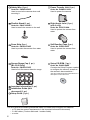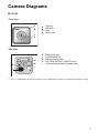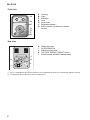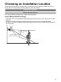
1
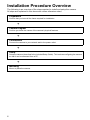
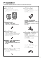
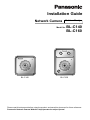
Installation Guide Network Camera Outdoor Ready Model No. BL-C140 BL-C140 BL-C160 BL-C160 Please read this document before using the product, and save this document for future reference. Panasonic Network Camera Website: http://panasonic.net/pcc/ipcam/ • This document is written for both the BL-C140 and BL-C160. Available features and operations vary slightly depending on the model. You can confirm the model no. of your camera by checking the model no. printed on the front of the camera. Features and operations that apply to the BL-C160 only are marked as “BL-C160 only” in this document. • The camera illustrations in this document depict the BL-C160. • Model number suffixes (“A”, “CE”, and “E”) are omitted from the following model numbers shown in this document, unless necessary. BL-C140A, BL-C140CE, BL-C140E, BL-C160A, BL-C160CE, BL-C160E Please read the included Important Information before proceeding. Complete Operating Instructions and all other documentation can be found on the included CD-ROM. • This document (Installation Guide) explains how to physically connect the camera to the power supply and network, as well how to mount or place the camera for regular use. • The Setup Guide describes how to set up the camera so that it can be accessed using a PC. • Refer to the Operating Instructions on the CD-ROM for details regarding the camera’s features. • Refer to the Troubleshooting Guide on the CD-ROM if you have any problems configuring or using the camera. Abbreviations • UPnP is the abbreviation for “Universal Plug and Play”. • The Network Camera is referred to as “the camera” in this document. • The Setup CD-ROM is referred to as “the CD-ROM” in this document. 2 Table of Contents Installation Procedure Overview................................................... Preparation...................................................................................... Camera Diagrams ........................................................................... Choosing an Installation Location................................................ 4 5 7 9 Detection Features............................................................................................................. 9 Mounting Location............................................................................................................ 13 Recommended Installation Locations .............................................................................. 14 Installation Examples ....................................................................................................... 15 Light Brightness (BL-C160 Only) ..................................................................................... 16 Effect of Brightness and Distance on Image Quality........................................................ 16 Connections.................................................................................. 17 Camera Mounting ......................................................................... 18 Adjusting Range and Sensitivity................................................. 23 Preventing Sensor Interference (BL-C160 Only) ............................................................. Adjusting Motion Detection Sensitivity ............................................................................. Adjusting Sensor Sensitivity (BL-C160 Only)................................................................... Sensor Range Caps (BL-C160 Only)............................................................................... 23 25 26 27 3 Installation Procedure Overview The following is an overview of the steps required to install and setup the camera. All steps are explained in this document unless otherwise noted. Preparation Confirm that you have all the items required for installation. Camera Diagram Confirm you know the names of the camera’s physical features. Connections Connect the camera to your network and to the power outlet. Setup Setup the camera (described in the included Setup Guide). This involves configuring the camera so that it can be accessed from a PC. Mounting Mount or place the camera. 4 Preparation Confirm the following items are included in the camera’s packaging. Main Unit (1 pc.) The appearance of your camera depends on which model you have purchased. BL-C140 AC Adaptor (1 pc.) Order No. PQLV206Y Cord Length: About 3 m (9 feet 10 inches) BL-C140A/BL-C160A BL-C160 Screw A (6 pcs.) Order No. XTB4 + 20AFJ Used for wall mounting the camera. Order No. PQLV216CE1Z Cord Length: About 3 m (9 feet 10 inches) BL-C140CE/BL-C140E/BL-C160CE/ BL-C160E Screw B (3 pcs.) Order No. XTB26 + 10GVW Used for securing the safety wire to the camera and for fixing the right-angle joint to the camera. AC cord (1pc. for BL-C140CE/ BL-C140E/BL-C160CE/BLC160E) Order No. PFJA02A006Z Cord Length: About 1.8 m (5 feet 11 inches) BL-C140CE/BL-C160CE Washer L (1 pc. for the screw A) Order No. XWG4F16VW Used when securing the safety wire to the wall. Washer S (1 pc. for the screw B) Order No. PSJA1106Z Cord Length: About 1.8 m (5 feet 11 inches) BL-C140E/BL-C160E Order No. XWG26D12VW Used when securing the safety wire to the camera. 5 Safety Wire (1 pc.) Order No. PQME10080Z Used to secure the camera when wall mounting it. Flexible Stand (1 pc.) Order No. PQKL10082Z1 Used to attach the camera to the wall Foam Strip (1pc.) Order No. PQHG10748Z Used to protect the camera from water Sensor Range Cap (1 pc.) [BL-C160 Only] Order No. PQHG10765Z Used to limit the sensor detection range Power Transfer Unit (1 pc.) Order No. PNWP3C160A Used to power the camera Right-Angle Joint (1 pc.) (with O-ring) Order No. PNYCC160A Used to protect the camera from water Self Bonding Tape (1pc.) Order No. PSHG1235Z Used to protect the camera from water Setup CD-ROM (1 pc.) Order No. PNQC1048Z Contains the Setup Program needed to configure the camera, as well as the camera’s documentation.* *See the included Important Information for a description of each document. Important Information (1 pc.) Installation Guide (this document) (1 pc.) Setup Guide (1 pc.) You will need the following additional items to install and configure the camera. – a PC (see the system requirements in the Important Information document) – 2 LAN cables (1 indoor cable and 1 outdoor cable) – a router 6 Camera Diagrams BL-C140 Front View A B C D A B C D Housing Indicator*1 Lens Lens cover E F G H I Safety wire hole DATA/POWER IN Stand mounting hole FACTORY DEFAULT RESET button Serial number and MAC address label Rear View G E H I F *1 See 1.1 Understanding the Camera Indicator in the Troubleshooting Guide on the CD-ROM for indicator meaning. 7 BL-C160 Front View A B C A B C D E F G Housing Light Indicator*1 Lens Lens cover Brightness sensor*2 Built-in sensor (pyroelectric infrared sensor) H I J K L Safety wire hole DATA/POWER IN Stand mounting hole FACTORY DEFAULT RESET button Serial number and MAC address label D E F G Rear View J H K L I *1 *2 8 See 1.1 Understanding the Camera Indicator in the Troubleshooting Guide on the CD-ROM for indicator meaning. The brightness sensor determines when the light turns on. Choosing an Installation Location Please read the following information about the camera’s motion detection feature and built-in sensor (BL-C160 only) before deciding where to mount the camera. Detection Features Motion Detection Feature The camera detects changes in the images being displayed. Active Motion Detection Range • When the color of moving objects and the background are similar, motion may not be correctly detected. • If there are sudden changes to overall light levels, motion may be incorrectly detected. • For up to 2 seconds immediately following the light turning on or off no detection will take place. (BL-C160 only) Camera Detection range angle About 45q Detection range length About 5 m (16 feet 5 inches) 9 Detection Range Characteristics of the Motion Detection Feature • Motion detection becomes more difficult as it becomes darker. • The motion detection function works by detecting changes in contour and brightness in moving objects. This is done in order to reduce inaccurate detections due to changes in brightness. • The camera can easily detect motion when objects move sideways in front of the camera, but cannot easily detect motion when objects move toward the front of the camera. Difficult to detect Easy to detect Detection range About 58q Camera 10 Built-in Sensor (BL-C160 Only) The camera’s built-in sensor is a pyroelectric infrared sensor, which means it uses infrared rays to detect temperature differences within its range that are emitted naturally by people, animals, etc. The sensor can be used to trigger the camera to buffer (i.e., temporarily store) camera images in its memory. You can view these images later as desired. The sensor can also be used to trigger the camera to transfer images to someone or somewhere, by FTP, E-mail, or HTTP. Built-in Sensor Sensor’s Active Detection Range • If there is no temperature difference between objects in range of the camera’s sensor and the surrounding environment, such as on a hot summer day, the sensor may not be able to detect properly. Conversely in winter when the outside air temperature becomes lower, differences in temperatures become greater which makes it easier for the sensor to perform detection. • If the camera is mounted facing a road, the sensor may detect incorrectly due to interference caused by passing cars. Refer to Example 1 or Example 2 on page 15 for examples of how to mount the camera so that it will not face roads that cause interference. When the camera is in a 20 °C (68 °F) environment Camera Detection range angle About 20q Detection range length About 5 m (16 feet 5 inches) 11 Detection Range Characteristics of the Built-in Sensor • The built-in sensor can easily detect temperature changes when objects move sideways in front of the camera, but cannot easily detect temperature changes when objects move toward the front of the camera. When the camera is in a 20 °C (68 °F) environment Easy to detect Diffictult to detect Easy to detect Detection range About 63q Camera 12 Mounting Location • Mount the camera in a sheltered place where it is not directly exposed to direct sunlight or the elements. • To ensure that camera images are displayed properly, do not mount the camera on a ceiling. • Do not mount the camera upside down. If the Panasonic logo is upside down, the camera is upside down. • Mount the camera where objects pass the camera from the sides. The sensor can easily detect temperature differences of objects moving sideways within the detection range, but cannot easily detect objects moving towards the sensor. For more information, see page 12. • Make sure to position the camera’s light so as not to disturb the surrounding area. (BL-C160 only) Built-in sensor Note Avoid these kinds of locations when mounting the camera. • Where people approach the camera by walking toward the front of the camera • Facing roads where many cars pass by (Even when separated by more than 5 m [16 feet 5 inches], cars can interfere with the performance of the built-in sensor) • Where car exhaust or warm air from heat-emitting devices cause rapid changes in temperature (The sensor may detect incorrectly due to rapid changes in temperature) • Where objects that move in the wind are located (e.g., tree branches, laundry hung out to dry) (The sensor may detect incorrectly due to temperature changes) • Where the camera can be exposed to direct sunlight or halogen light • Where there is vibration or shock • Where the camera can be exposed to fire, heating devices, or interference from magnetic devices • Where reflective objects or objects that can interfere with heat detection, such as glass, are in front of the camera • In a greasy or moist place • Near devices that emit radio waves, such as mobile phones • Where the camera can be exposed to strong chemicals or noxious fumes • Where the camera can be exposed to air containing high levels of salt, ammonia, sulphur etc. (Exposure to such conditions can reduce the operating life of the camera) • In places that have shade during the day, bright lighting at night, or where light levels often change • In places with the following types of backgrounds and background lighting (Faces can appear dark which makes it difficult to determine facial characteristics) In places where large parts of the background are open to bright light In places with white walls in the Bright background, which light reflect sunlight toward the camera White walls Where the object has the sun at its back 13 Recommended Installation Locations Top View Where it is easy to detect people coming off the street towards the property and where passing cars do not cause interference. It is easier to detect people when they pass in front of the camera. A sensor range cap can be attached to the camera to control the detection range. For more information, see page 27. Difficult to detect Distance About 3 m (9 feet 10 inches) Easy to detect Camera Entrance Side View Camera Height About 3 m (9 feet 10 inches) Distance About 3 m (9 feet 10 inches) 14 Installation Examples Example 1: For detecting people on your property Recommend Where it is easy to detect people coming off the street towards the property and where passing cars do not cause interference. It is easier to detect people when they pass in front of the camera. Not Recommend People or cars passing by on the street are easy to detect, but people approaching the camera by walking toward the front of the camera are difficult to detect. Difficult to detect Easy to detect Difficult to detect Easy to detect Camera Camera Entrance Entrance Example 2: For detecting people entering an area like a garage Recommend Intruders entering the garage will be easy to detect, but people or cars passing by on the street will be difficult to detect. It is easier to detect people when they pass in front of the camera. Difficult to detect Not Recommend People or cars passing by on the street will be easy to detect, but intruders entering the garage will be difficult to detect. Easy to detect Street Street Camera Easy to detect Easy to detect Difficult to detect Camera Note • Cameras should be mounted so that they can view over parked cars, or other objects in the garage. 15 Light Brightness (BL-C160 Only) The camera features a built-in light that can turn on automatically when it is dark, or when the camera’s motion detection or sensor features are triggered. The following brightness levels are measured 3 m (9 feet 10 inches) from the camera. Directly in front of the camera: about 8.5 lx 20° to the sides of the camera: about 2.5 lx Note that the light may not provide enough light to illuminate the surrounding area. Light Effect of Brightness and Distance on Image Quality Distinguishing faces is difficult in the following situations. • When the person is too far from the camera (Generally, faces should be distinguishable up to 3 m [9 feet 10 inches] away, however, other variables, such as shadowing, backlight, angle, etc., may affect the distance at which faces can be recognized.) • In the late afternoon and at night, or other times when the surrounding area is dark • When people are moving (which causes blurring) in front of the camera 16 Connections Connect the camera to your router and to the power outlet as described below. • Before proceeding, confirm that your PC is connected to your router and can access the Internet. Also confirm that your router’s UPnP™ feature is enabled. (Most routers have UPnP™ turned off by default.) Wall Outside Inside AC adaptor Power transfer unit Outdoor LAN cable * To the power outlet (For BL-C140CE/ BL-C140E/ BL-C160CE/ BL-C160E use an AC cord) Router LAN cable * Use a LAN cable that is no more than 30 m (98 feet 5 inches) long to connect the camera and the power transfer unit. 17 Camera Mounting Caution • Do not drive the screws into a soft material. Drive the screws into a secure area of the wall, such as a column, otherwise the camera may fall and be damaged. • Make sure you attach the safety wire when mounting the camera, to prevent the camera from falling. • Do not place the camera near any heat emitting devices (e.g., water heaters, air conditioners). (Placing the camera near heat emitting devices can cause the built-in sensor to not detect properly.) Note • Use a LAN cable that is no more than 30 m (98 feet 5 inches) long to connect the camera and the power transfer unit. • Use screws that are appropriate for the material of the wall. • The included screws are for use with wooden walls only. • Prolonged exposure to direct sunlight or halogen light may damage the camera’s image sensor. Mount the camera appropriately. • Make sure to waterproof any openings or holes made during installation. • When connecting the cable, waterproof the cable using the included right-angle joint, foam strip and self bonding tape. • When installing cables through the ground, do not connect cables under the ground. Install cables through a conduit to protect them from water. • Refer to page 9-12 for information about the operation of the built-in sensor before deciding where to install the camera. 1 Secure the safety wire to the camera using screw B (included) and washer S (included). • Make sure you attach the safety wire when mounting the camera, to prevent the camera from falling. Safety wire Washer S Screw B 2 18 Remove the tab on the flexible stand, then pass an outdoor LAN cable through the notch. 3 Mount the flexible stand firmly to the wall using screw A (included). • Do not drive the screws into a soft material. Drive the screws into a secure area of the wall, such as a column, otherwise the camera may fall and be damaged. • Use screws that are suited for the type of material the camera is mounted to. • Be careful not to nip the cable. • Make sure the flexible stand is firmly mounted on a beam (at least 25 mm [1 inch] thick) etc. When there is no beam, apply a board on the other side of the wall to make sure the camera does not drop. Screw A At least 25 mm (1 inch) 4 Pass the cable through the right-angle joint and attach the right-angle joint by fastening screw B. • Insert the LAN cable until it clicks into to place. • Make sure that the “↑UP” symbol is pointing up when attaching the right-angle joint to the camera. • Securely fasten all screws. 19 5 Wrap the included foam strip around the cable, insert it into the opening of the right-angle joint, and then wrap at least the first 50 mm (1 15/16 inches) of the cable using the included self bonding tape. • • • • Leave about 10 mm (3/8 inches) of the foam exposed, as shown. Stretch the tape to twice its length when you wrap the cable. Overlap the tape when you wrap the cable. Make sure that there are no gaps in the wrapped tape for water to enter. 50 mm (1 15/16 inches) 6 Attach the camera by screwing the threaded mount into the stand mounting hole. • Loosen the flexible stand grip to make adjusting the angle of the camera easier. Once the camera is adjusted to the desired angle, retighten the grip firmly into place. Threaded mount Grip 7 20 Adjust the camera position. • Leave some slack in the cable, as shown. 8 Secure the safety wire to the wall using screw A (included) and washer L (included). • When mounting to a hard surface like mortar or concrete, use an anchor to help secure the camera to the wall. • Leave some slack in the safety wire, as shown. Safety wire Washer L Screw A 9 Connect a LAN cable to the power transfer unit and to the switching hub, router, etc. • The power transfer unit can be fixed in place with 2 pieces from screw A (4 mm x 20 mm [3/16 inch x 13/16 inch]). LAN Cable 10 Connect the outdoor LAN cable connected to the camera to the power transfer unit. 11 Connect the AC adaptor to the power transfer unit and plug the other end into the power outlet. • The camera will activate. To the power outlet (For BL-C140CE/BL-C140E/ BL-C160CE/BL-C160E use an AC cord) To router Hook for AC adaptor 21 When mounting on a mortar or concrete surface • Prepare anchors for 4 mm (3/16 inch) diameter screws for mounting. A Place the flexible stand on the wall where you plan to mount the flexible stand and mark the points where you are going to make holes. B Make holes with an electric drill. Insert anchors (customer-provided) into the holes and push them inside the holes with a hammer. • Mortar walls break easily when drilling. Be careful of pieces of mortar which may become loose and fall. Drill for concrete (in case of tile, use a drill for tile) C Mount the flexible stand using the screws. 22 Adjusting Range and Sensitivity Preventing Sensor Interference (BL-C160 Only) If objects are interfering with the built-in sensor, use one of the included sensor range caps to cover the corresponding area of the sensor. For Built-in Sensors Example 1 If there are interfering objects (such as cars) on one side or corner of the screen, attach cap 1 or 2 to cover the desired area of the sensor. • In the example below, the object in the upper-left corner of the image may interfere with the sensor, therefore, the upper-right corner of the sensor should be blocked using a sensor range cap. 23 Example 2 If there are interfering objects (such as heat emitting devices) being displayed on both sides of the screen, use cap 3 to block the parts of the sensor that are detecting the interfering objects (in this case on the left and right-hand sides). Heat emitting device Other interfering object 24 Adjusting Motion Detection Sensitivity The sensitivity of the motion detection can be adjusted to match the installation environment. For more information, see 2.10 Adjusting Motion Detection Sensitivity in the Operating Instructions on the CD-ROM. 25 Adjusting Sensor Sensitivity (BL-C160 Only) By adjusting the sensitivity of the built-in sensor, the detection range can change in the following ways. The temperature and other qualities of the camera location may affect the detection range. For more information, see 2.9 Adjusting Sensor Sensitivity (BL-C160) in the Operating Instructions on the CD-ROM. Temperature: 20 °C (68 °F) N High • In certain installation setups or environments it may be necessary to increase sensor sensitivity for the camera to be operational. • Increasing sensor sensitivity can cause the sensor to make inaccurate detections. Top View Detection range About 5 m About 6 m (19 feet 8 inches) (16 feet 5 inches) N Middle Top View Detection range About 5 m (16 feet 5 inches) N Low Top View Detection range About 4 m About 5 m (13 feet 1 inch) (16 feet 5 inches) N Very Low Top View Detection range 26 About 3 m (9 feet 10 inches) About 5 m (16 feet 5 inches) Sensor Range Caps (BL-C160 Only) When there are objects that you do not want to detect with the built-in sensor, a sensor range cap can be attached to the camera to control the detection range. There are 4 sensor range caps: the standard cap (attached at the time of purchase), cap 1, cap 2, and cap 3. Each cap blocks detection to various directions and degrees. Caps can be attached at 45° angles. Select the cap and attachment angle to best suit your needs. See the next page for details of each cap’s detection range. Note • Keep the sensor-range caps out of reach of children to prevent swallowing. How to Attach Caps Align the cap’s tab with the notch in the sensor, then insert the cap. Notch Tab Note • Incorrectly inserted caps can affect detection capabilities. How to Remove Caps Pinch the edge of the cap to lift it up, then remove it. 1. Pinch 2. Remove 27 Detection Ranges for the Sensor Range Caps Sensor range caps can be used to prevent detections when the temperature changes in certain areas of the detection range. Differing temperatures will affect how far the sensor can detect within the detection range. Confirm the different detection ranges in the following explanations. Please note that the below figures are a guide to the detection ranges when the Sensor Sensitivity is set to “Middle” (see page 26). Sensor Range Cap Temperature: 20 °C (68 °F) Top View Standard cap (attached at time of purchase) Detection range About 5 m (16 feet 5 inches) N If there are objects that you do not want to be detected on the right-hand side of the detection range, attach the cap to block the right side. Attach cap 2 or 1 as shown in the diagram below. The number is shown on the side of the cap. Top View Cap 2 Cap 2 Cap 1 If you want to block more of the right-hand side than with cap 2, attach cap 1. Detection range About 5 m (16 feet 5 inches) Note • If there are objects that you do not want to be detected on the left-hand side of the detection range, attach cap 2, or cap 1 to the left side. (In this case, the detection ranges shown on the right will be reversed.) N To block detection on both sides of the detention range, attach cap 3 as shown below. Top View Cap 3 Detection range About 5 m (16 feet 5 inches) Cap 3 Note • The position of the cap determines the area of the detection range that is blocked. 28 Temperature: 0 °C (32 °F) Temperature: 30 °C (86 °F) Top View Top View Detection range Detection range About 4 m (13 feet 1 inch) About 6 m (19 feet 8 inches) Top View Top View Detection range Detection range About 4 m (13 feet 1 inch) About 6 m (19 feet 8 inches) Top View Top View Detection range Detection range About 6 m (19 feet 8 inches) About 4 m (13 feet 1 inch) 29 Note 30 Note 31 © Panasonic System Networks Co., Ltd. 2008 PQQX16442XA KK0408CM2020