1
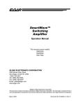
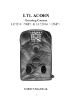
LED Indicators—NPort 5200A’s top panel has four LED indicators,
which are described in the following table.
Rear Panel View
NPort 5200A Series
Quick Installation Guide
Reset button
RJ45 10/100M Ethernet port
Power input
First Edition, July 2010
Top Panel View
1. Overview
NPort 5200A series device servers are compact, palm-sized data
communication devices that allow you to control RS-232 (NPort 5210A),
RS-422/485 (NPort 5230A), and RS-232/422/485 (NPort 5250A) serial
devices over a TCP/IP-based Ethernet.
Note: “-T” indicates an extended temperature model.
DIN-Rail
screw hole
2. Package Checklist
Wallmount
screw hole
Before installing the NPort 5200A series device server, verify that the
package contains the following items:
y
y
Power Adaptor (NPort 5200A-T doesn't include this accessory)
4 stick-on pads
Steady on: Power is on and the NPort is booting up.
Blinking: Indicates an IP conflict, or DHCP or
BOOTP server is not responding properly.
Steady on: Power is on and the NPort is functioning
Ready
normally.
Green
Blinking: The NPort has been located by the NPort
Administrator’s Location function.
Off Power is off, or a power error..
Orange 10 Mbps Ethernet connection.
Red
Green 100 Mbps Ethernet connection.
Link
Off
Ethernet cable is disconnected.
Orange Serial port is receiving data.
Adjustable pull high/low resistor and terminator for RS-422/485
Front Panel View
y
Document & Software CD
y
Quick Installation Guide
y
Product Warranty Statement
Remove the NPort 5230A/5250A’s top
cover and you will find DIP switches to
adjust each serial port’s pull-high, pull-low,
and terminator. Do not use the 1 KΩ setting
with RS-232 mode, as doing so will
degrade the RS-232 signals and shorten the
communications range.
Male DB9 serial port
Terminal Block
Stick-on pad
Optional Accessory
y
LED Function
Serial port is transmitting data.
P1, P2 Green
No data is being transmitted or received through the
Off
serial port.
1 NPort 5200A serial device server
y
LED LED
Name Color
NPort 5210A/5250A
DK-35A: DIN-Rail Mounting Kit (35 mm)
Notify your sales representative if any of the above items are missing or
damaged.
3. Hardware Introduction
As shown in the following figures, NPort 5200A series device servers
have two male DB9 ports for transmitting RS-232 (NPort 5210A), or
RS-232/422/485 (NPort 5250A) serial data and have two 5-pin terminal
block ports for transmitting RS-422/485 (NPort 5230A).
NPort 5230A
Reset Button—Press and hold the Reset button for 5 seconds to load
factory defaults: Use a pointed object, such as a straightened paper clip or
toothpick, to depress the reset button. This will cause the Ready LED to
blink on and off. The factory defaults will be loaded once the Ready LED
stops blinking (after about 5 seconds). At this point, release the reset
button.
Port 1
Port 2
ON
1
SW
ON
OFF
1
Pull-high resistor
1 KΩ
*150 KΩ
2
2
Pull-high resistor
1 KΩ
*150 KΩ
*Default
P/N: 1802052000010
— 1—
—2—
3
—3—
3
Terminator
120Ω
*---
4. Hardware Installation Information
7. Specifications
NPort 5210A—DB9 male (RS-232) port pinouts
1
STEP 1: After removing the NPort 5200A series device server from the
box, the first thing you should do is connect the power adaptor.
STEP 2: Connect the NPort 5200A series device server to a network. Use
a standard straight-through Ethernet cable to connect to a hub or switch.
When setting up or testing the NPort 5200A series device server, you
might find it convenient to connect directly to your computer’s Ethernet
STEP 3: Connect the NPort 5200A series device server’s serial port to a
serial device.
5
6
Pin Number
1
2
3
4
5
6
7
8
9
9
STEP 4: Placement options.
In addition to placing the NPort 5200A on a desktop or other horizontal
surface, you may also make use of the DIN-Rail or Wall Mount options,
as illustrated below.
RS-232
DCD
RxD
TxD
DTR
GND
DSR
RTS
CTS
---
Power Requirements
1
2
3
4
5
RS-422/485
(4W)
TxD+(B)
TxD-(A)
RxD+(B)
RxD-(A)
GND
12 to 48 VDC
Power Consumption
119 mA@12V, 65 mA@24V
Operating Temperature 0 to 60°C (32 to 140°F), for standard models
-40 to 75°C (-40 to 167°F), for -T models
NPort 5230A—Terminal Block (RS-422/485) port pinouts
Pin
Number
1
2
3
4
5
Power Input
RS-485
(2W)
----Data+(B)
Data-(A)
GND
Operating Humidity
5 to 95% RH
Dimensions
100 x 111 x 26 mm
(3.94 x 4.37 x 1.02 in)
Åwith ears
77 x 111 x 26 mm
(3.03 x 4.37 x 1.02 in)
Åwithout ears
Serial Line Protection
15 KV ESD for serial port
Level 1 Surge, EN61000-4-5
Magnetic Isolation
1.5 KV for Ethernet
Power Line Protection
Level 2 Burst (EFT), EN61000-4-4
Level 3 Surge, EN61000-4-5
Regulatory Approvals
FCC Class A, CE Class A, UL, LVD
NPort 5250A—DB9 male (RS-232/422/485) port pinouts
1
5
5. Software Installation Information
To install NPort Administration Suite, insert the NPort Document &
Software CD into your computer’s CD-ROM drive. Once the NPort
Installation CD window opens, click on the Software folder, and then
follow the instructions on the screen.
To view detailed information about NPort Administration Suite, click
on the Documents folder, and then select “NPort 5200A Series User’s
Manual” to open the pdf version of the user’s guide.
6. Pin Assignments
Ethernet Port Pinouts
1
8
Pin Number
1
2
3
6
—4—
6
9
Pin
Number
RS-232
1
DCD
TxD-(A)
---
2
RxD
TxD+(B)
---
3
TxD
RxD+(B)
Data+(B)
4
DTR
RxD-(A)
Data-(A)
5
GND
GND
GND
6
DSR
---
---
7
RTS
---
---
8
CTS
---
---
9
---
---
---
Ethernet
Tx+
TxRx+
Rx-
RS-422/
485 (4W)
RS-485
(2W)
Click here for online support:
www.moxa.com/support
The Americas:
Europe:
Asia-Pacific:
China:
+1-714-528-6777 (toll-free: 1-888-669-2872)
+49-89-3 70 03 99-0
+886-2-8919-1230
+86-21-5258-9955 (toll-free: 800-820-5036)
© 2010 Moxa Inc. All rights reserved.
Reproduction without permission is prohibited.
—5 —
—6—