1
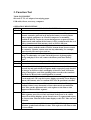
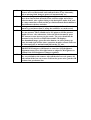
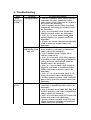
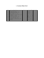
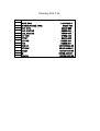
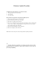
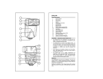
DDC4000001
Digital Camera
Model : DDC400
NOV. 2005
Contents
Warning
Function Test
Troubleshooting
Explode diagram
Service Parts Lists
Packing Diagram
Firmware update procedure
2. Warning
If you are using AC power adapter, unplug the adapter from the AC power
outlet after you have disconnected the camera.
Do not touch the power plug during a thunderstorm if you are using the AC
power adapter. This may cause an electrical shock.
Do not insert or drop metallic or inflammable foreign objects into the
camera through access points such as the memory card slot. This may cause
a fire or an electrical shock.
If the camera has been dropped or if the camera case has been damaged,
turn the camera off and then disconnected the power source (batteries or
AC power adapter). Do not continue to use the camera as this may cause a
fire or an electrical shock.
Do not cover or wrap the camera or the AC power adapter with a cloth. This
may cause heat to build up and distort the case and cause a fire. Always use
the camera and its accessories in well-ventilated locations
Do not use batteries other than those specified for use with your camera.
The use of unsuitable batteries may result in the batteries splitting or
leaking and causing a fire, injury, or soiling of the battery compartment. If
the batteries leak, clean and wipe the battery compartment carefully and
install new batteries.
3. Function Test
TOOL/EQUIPMENT
SD card*2, TV, AC adapter, lens-wiping paper
USB cable, flower, accessory, computer
OPERATION DESCRIPTION
ITEM
OPERATON DESCRIPTION
Part I
1
2
3
4
Part II
Take out the camera, open the battery cover and insert SD card.
Camera cannot be powered on if insert the battery reversely. Insert
battery rightly and power on. Check if can power on normally.
Confirm if the FW version is correct during power on process. Enter
capture mode and confirm if the battery icon is consistent with the real
battery situation and if the memory icon on LCD is SD icon.
Knock the camera on the desk slightly for three times (5cm distance
between camera and the surface of desk, bottom down, do not scratch
the cosmetic). Camera cannot come out any abnormity, for example,
power breaks, SD card ejects, and etc.
Take a photo in Auto mode and press Playback button to confirm the
image. No abnormity can come out in the process of photography,
storage and play. Power off; remove the battery and close battery
cover.
When all the above are ok, power off and put into the line.
A
1. Insert the 3.0 V AC adapter, power on in the Auto mode. View
towards beyond and vicinity in capture mode respectively, and check if
the images on LCD are clear and display is biased. Check LCD noise
facing to dark place, and if the spoiling points accord to the standard.
Check the LCD has feeder and brightness is normal.
2. Revolve the dial for one circumference in the revolving mode, check
if each mode on LCD’s top left corner displays normally. Press Display
button (OK button) twice to confirm if TFT-LCD operation is normal.
B
1.Press W/T to stretch out to Tele, and then draw back to W segment,
confirm if there is any abnormity of lens when stretch out and draw
back. Take out the abnormal ones; take a photo to the flower with
suppressed flash in Wide segment.
2. When view towards vicinity (about 1.0m) or beyond (over 2.5m) in
Wide segment, press S1 to focus, and check if the focus is ok, which
means focus frame displays green. Stretch out to T segment and repeat
the focus action. That the focus frame displays red is NG. Take out and
maintain.
3. Press the cross button (Self-timer mode), TFT-LCD displays
self-timer symbol and self-timer’s time. Take a photo to the flower with
2s’ forced flash.
C
D
E
F
G
H
Make the spot test of 10 PCS from each section, trigger to take 30
pictures in forced flash mode and confirm if there is any abnormity,
such as missing flash, hang on, power off automatically etc.
Shift to landscape mode and take a piece of photo towards beyond
(more than 3m) in flash off mode. Then switch to night and red-eye
reduction mode, take a photo facing to the dark place under desk, and
the camera must have flash and the pre-flash and main flash shall have
clear differences before and after.
Shifting to record mode, record symbol is displayed. Press Shutter
button to record more than 5s, using the sound box to catch record.
Connect TV and press playback button to enter into playback mode,
view the pictures. There should not be NG pictures and the pictures
should not have color aberration. Select the Movie document, press
SET button to enter into movie play mode; The voice should not be
abnormal or too low. Press Wide button and LCD displays
nine-thumbnail image; press direction button can select picture up,
down, left and right. All the above operation should e normal. Take out
the abnormal ones to maintain and pull out the TV wire.
Draw out 10 PCS from each section, shift to SETUP mode, select LCD
BRIGHTNESS and press OK button to enter into LCD brightness
adjustment menu. Press left-right button to adjust LCD brightness to
confirm if the LCD brightness changes regularly.
Select format menu to format the internal memory of camera. After
this, set to default to the camera. After all the above are ok, power off
and confirm if the lens can retract. Pull out the power wire; put the OK
products into production line.
4. Troubleshooting
Item
Charge
Triggering
System
Lens
system
NG point
NG Analyzing solution
Charging failure 1>. Check if connectors TP45-TP50 of J401 are
cold solder, no solder, insufficient solder,
short-circuit, wrong solder, and etc. if there is
any, remove the abnormity;
2>. If (1) is normal, check if U401 and related
components and voltage are normal, remove
the abnormity;
3>. If (1), (2) are normal, check if Q402 and
T401 are normal, remove the abnormity;
4>. If (1), (2), (3), check if D401, R401~R406
and big capacitor are normal, remove the
abnormity;
5>. If above are normal, check if controlled pins
of MCU board are normal, remove the
abnormity.
Triggering failure/ 1>. Check if tube is offset or installed reversely,
flash missing/ flash
wires of tube are cold solder or insufficient
only once
solder, remove the abnormity;
2>. If (1) is normal, check if copper foil of
reflector contact well;
3>. If (1), (2) are normal, check if big capacitor
is insufficient solder and voltage is normal. If
voltage is too low, check if R401~R406 are
normal, remove the abnormity;
4>. If (1), (2), (3) are normal, check if Q403 is
triggered, cold solder or insufficient solder,
C505 is cold solder or broken, remove the
abnormity;
5>. If (1), (2), (3), (4) are normal, check if +5V
voltage is normal, remove the abnormity;
6>. If above items are normal, check controlled
pins on MCU board are normal, removes the
abnormity.
Lens flexing issue 1>. Check if connecting board of lens is NG,
cold solder or insufficient solder, remove the
abnormity;
2>. If (1) is normal, check if R84, R87, R89, R90
on MCU board are cold solder or insufficient
solder, remove the abnormity;
3>. If (1), (2) are normal, check if CN1 and CN2
contact well, remove the abnormity;
4>. If above items are normal, check if U8 and
related circuit are cold solder or insufficient
solder, remove the abnormity.
Aperture shift NG
Lens focus failure
Lens resolution
issue
Lens noise
Power and Power on failure
system
(without current)
1>. Check if lens connecting board contact NG,
cold solder or insufficient solder, remove the
abnormity;
2>. If (1) is normal, check if R80, R81, R82,
R83, R85, R86 are cold solder or insufficient
solder, remove the abnormity;
3>. If (1), (2) are normal, check if CN1 and CN2
contact well, remove the abnormity;
4>. If above items are normal, check if U8 and
related circuit are cold solder or insufficient
solder, remove the abnormity.
Check if lens and around components are
normal; remove the abnormity.
1>. Check if CCD is assy well, remove the
abnormity;
2>. Check if lens is NG. Change lens
1>. Check if lens is NG. Change lens
2>. Check if the components around lens are
cold solder or insufficient solder, remove the
abnormity.
1>. Check if the connection between MCU
panel and soft connecting panel of Shutter is
NG, remove the abnormity;
2>. Check if the fuse F1 on power board is
broken, remove the abnormity;
3>. Check if crystal Y3 is short-circuit, cold
solder or no solder, remove the abnormity;
4>. Check if the POWCTRL related circuit is
cold solder, insufficient solder, short-circuit,
component broken, and etc. Remove the
abnormity;
5>. Check if the related tube pins of U11 are
cold soldered, insufficient solder, no solder,
short circuit, and etc. Remove the abnormity.
Power on fail (with 1>. Check if the connection between MCU
current)
panel and soft connecting panel of Shutter is
biased or NG, remove the abnormity;
2>. Reuse the USB update FW, confirm if the
camera can power on;
3>. Check if U10 is cold solder, no solder or
insufficient solder, remove the abnormity;
4>. Record U10 again to confirm if the camera
can power on;
5>. Check if S3.3V is normal, remove the
abnormity;
6>. Check if inductance and audion on power
board are cold solder or short circuit; remove
the abnormity.
Power on without
sound/ with
abnormal sound
The shift between
AC power and
battery is NG.
Display
TFT-LCD image
and image unstable
system
TFT-LCD white
image
1>. Check if two poles of buzzer are cold solder
or broken, remove the abnormity;
2>. Check if buzzer is ok, remove the
abnormity;
3>. Check if R15, Q5, R8, R113 are cold solder,
insufficient solder or NG, remove the
abnormity.
1>. Check if power connector is cold solder,
insufficient solder, short circuit or NG, remove
the abnormity;
2>. Check if D15 is broken, short circuit or
insufficient solder; remove the abnormity.
Check if golden finger of CCD FPC and
connector contact well.
1>. Check if LCD interface is inserted to the
bottom or the interface is cold solder, root of
LCD FPC is broken, remove the abnormity;
2>. Check if each group of power +5VD,
+8.5VL, 3.3VD, -8.0VL of LCD are normal.
TFT-LCD display 1>. Check if switch of shutter is normal, remove
menu without image the abnormity;
2>. Check if CCD flex board assy well, remove
the abnormity;
3>. Check if output of CCD related components
is OK, remove the abnormity;
4>. Check if each group of voltage of CCD is
OK; remove the abnormity.
TFT-LCD color
1>. Check if CCD flex board is OK or assy OK,
aberration/ color
remove the abnormity;
difference
2>. Check if soldering of CCD is short-circuit,
insufficient solder or cold solder, remove the
abnormity;
3>. Check if capacitor C503, Q501 on CCD flex
board are OK, remove the abnormity;
4>. Check if U1 is cold solder, insufficient solder
or broken, remove the abnormity.
TFT-LCD no image 1>. Check if TV connector is OK, remove the
abnormity;
but TV displays
2>. Check if VIDEO_DET is OK; remove the
normally
abnormity.
TV no image but
1>. Check if AV connector and related
LCD displays
components are OK, remove the abnormity;
normally
2>. Check if VIDEO_DET is OK; remove the
abnormity.
Others
1>. Check if USB connector is OK, remove the
abnormity;
2>. Check if USB_DTC related circuit is OK,
remove the abnormity;
3>. Confirm if ASIC and related circuits are
OK; remove the abnormity.
TV play/ no sound/ 1>. Check if AV connector and R315, C181 are
OK, remove the abnormity;
noise/ voice too low/
2>. Check if wires of microphone are solder
too high
well, remove the abnormity;
3>. Check if microphone is OK; remove the
abnormity.
USB connecting
failure or can not
search the disk
This document cannot be modified and implemented without prior approval
from Premier.
5. Explode diagram
9R 744-3000
9R 747-3100
9Q 334-4600-99
9Q 344-7000
9Q 347-0100
9Q 344-8000
02411-0003-00
9R746-6000
9R 747-4100
9R 744-2000
Reference only
Part order; please refer to Sec 6 Service
Parts List
Any alteration of parts number is conducted
by sales representative.
6. Service Parts List
Item
1
2
3
4
5
6
7
8
9
10
Parts Name
MCU_DIP_PCB_ASY
STROBE_DIP_PCB_ASY
SWITCH_DIP_PCB_ASY
LENS ASSY
BATTERY-HOLDER-SUB-ASM
BATTERY-COVER
FRONT-GRIP-SUB-ASM
BACK-GRIP-SUB-ASM
BATTERY-COVER-SUB-ASM
BUZZER
Pcs / set
1
1
1
1
1
1
1
1
1
1
Premier P/N Remark
9Q347-0100
9R747-4100
9R747-3100
9R746-6000
9Q344-8000
9Q334-4600-99
9R744-2000
9R744-3000
9Q344-7000
02411-0003-00
Packing Diagram
Packing Part List
No
Part name
1
2
3
4
5
6
7
8
9
10
11
12
13
14
HDPE BAG
LB ASSURANCE TAPE
OUT_CTN
PAD, VIVITAR
PAD, VIVITAR
CD ROM
STRAP
KIT PAD
PAD
FCC LB
KIT BOX
SHEET
IM
POUCH
Part number
04039-023-1
04238-765
9E539-602
9E539-694
9E539-695
9P839-A00
9Q338-000
9Q339-200
9Q339-201
9R738-5000-00
9R739-2400-00
9R739-4800-00
9R739-4000-01
9R739-3000-00
Firmware Update Procedure
To update this camera firmware, you will need to have
1. The new firmware file from Premier.
2. One SD card.
3. One card reader.
Please follow the steps below to perform the update process:
1. Change the update file name to “DC4345.bin”;
2. Insert a SD card with F/W to the card reader;
3. Plug in the AC adapter into the camera;
4. Press "S1" & "Playback" button at the same time and press “Power” button, then
loosen “Power” button, LCD will display the image and camera enters update
process automatically and LED blinks;
5. When LED stops blinking, it means update ok;
6. Pull out AC adaptor, remove SD card.
Note: Don’t remove the power source during firmware update procedures.
Premier will not be responsible to any damage caused by end-users while
updating firmware by themselves. Always come to Premier’s service center for
processing the updating.