1
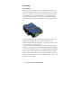
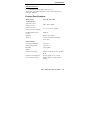
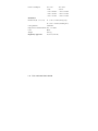
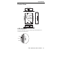
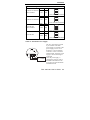
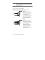
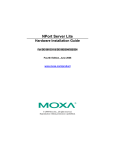
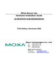
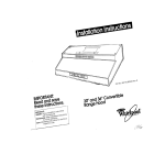
Moxa TCC-120/120I User’s Guide www.moxa.com/product Eighth Edition, August 2009 © 2009 Moxa Inc. All rights reserved. Reproduction without permission is prohibited. Moxa TCC-120/120I User’s Guide The software described in this manual is furnished under a license agreement and may be used only in accordance with the terms of that agreement. Copyright Notice Copyright © 2009 Moxa Inc. All rights reserved. Reproduction without permission is prohibited. Trademarks MOXA is a registered trademark of Moxa Inc. All other trademarks or registered marks in this manual belong to their respective manufacturers. Disclaimer Information in this document is subject to change without notice and does not represent a commitment on the part of Moxa. Moxa provides this document “as is,” without warranty of any kind, either expressed or implied, including, but not limited to, its particular purpose. Moxa reserves the right to make improvements and/or changes to this manual, or to the products and/or the programs described in this manual, at any time. Information provided in this manual is intended to be accurate and reliable. However, Moxa assumes no responsibility for its use, or for any infringements on the rights of third parties that may result from its use. This product might include unintentional technical or typographical errors. Changes are periodically made to the information herein to correct such errors, and these changes are incorporated into new editions of the publication. Technical Support Contact Information www.moxa.com/support Moxa Americas: Toll-free: 1-888-669-2872 Tel: +1-714-528-6777 Fax: +1-714-528-6778 Moxa China (Shanghai office): Toll-free: 800-820-5036 Tel: +86-21-5258-9955 Fax: +86-10-6872-3958 Moxa Europe: Tel: +49-89-3 70 03 99-0 Fax: +49-89-3 70 03 99-99 Moxa Asia-Pacific: Tel: +886-2-8919-1230 Fax: +886-2-8919-1231 Table of Contents Chapter 1 Introduction 1-1 Overview ...................................................... 1-2 Product Features .......................................... 1-4 Package Checklist ........................................ 1-4 Product Specifications .................................. 1-5 Product Views............................................... 1-7 LED Indicators .............................................. 1-7 Chapter 2 Installation 2-1 Hardware Installation.................................... 2-2 1 Chapter 1 Introduction The TCC-120 and TCC-120I are RS-422/485 isolated repeaters, and the TCC-120I comes with 2 KV isolation protection. The following topics are covered in this chapter: Overview Product Features Package Checklist Product Specifications Product Views LED Indicators Overview Introduction Many important devices used in today’s industrial environment use the RS-422 or RS-485 interface for data transmission. In some cases however, it is necessary to extend the transmission distance between RS-422/485 devices. This is where the TCC-120/120I RS-422/485 Repeaters come in. Simply wire the power terminal block, wire the two signal terminal blocks, set the DIP switches, and you’re ready to go. The RS-422/485 standards use a differential signal for transmitting data signals. In addition to distance and multi-drop issues for industrial applications, housing, wiring, power supply, and over-surge protection are also serious concerns. The TCC-120I provides isolation protection for users who need an industrial grade repeater to extend RS-422/485 transmission distance and increase networking capability. The superior industrial application design of this product, which includes DIN-Rail mounting, terminal block wiring, external terminal block power, and optical isolation for system protection, makes the TCC-120/120I suitable for use in critical industrial environments. 1-2 TCC-120/120I User’s Guide Introduction Built-in RS-485 ADDC™ Intelligence ADDC™ (Automatic Data Direction Control), a Moxa leading technology, uses a clever hardware solution to take care of the RS-485 data flow control problem. ADDC™ is a hardware data flow solution that automatically senses and controls data direction, making the handshaking signal method unnecessary. Isolation Moxa’s electrical isolation technology uses two photo couplers to create a gap in each electrical signal. One photo coupler transforms the electrical signal into a light signal, which is transmitted across a small gap, and then the other photo coupler transforms the light signal back into an electrical signal. In this way, the two electrical circuits are completely isolated from each other, limiting the damage that could otherwise be caused by power surges in the electrical signal. Reverse Power Protection The Reverse Power Protection feature provides extra protection against accidentally connecting the power cables to the wrong terminal. The converter is designed to automatically detect which power wire is positive and which is negative, and then adjust the power supply accordingly. DIP Switch Selectable Terminator For many products of this type, the termination resistor is set by a jumper located inside the product’s casing, so that the user must open the casing to disable or change the resistor’s strength. Moxa offers a better solution. The TCC-120/120I’s terminator is set with a DIP Switch located on the outside of the converter’s casing. TCC-120/120I User’s Guide 1-3 Auto Baudrate Detection The TCC-120/120I incorporates a method for automatically detecting the serial signal’s baudrate by hardware. This is an extremely convenient feature for the user. Even if a device’s baudrate changes, the signal will still be transmitted through the RS-422/485 repeater without any problems. Product Features • Boost serial signal for extending transmission distance up to an additional 1.2 km • Wall or DIN-Rail mountable • Terminal block for easy wiring • Power input from terminal block • DIP switch setting for built-in terminator(120 ohms) • PWR, Tx, Rx LEDs • Operating temperature from -20 to 60°C • 2 KV Isolation (for the TCC-120I) Package Checklist Before installing the TCC-120/120I, verify that the package contains the following items: Standard Accessories: • TCC-120 or TCC-120I • User’s Guide • Warranty Card • 5-contact terminal block connector x 2 • 3-contact terminal block connector x 1 1-4 TCC-120/120I User’s Guide Introduction Optional Accessory • 2 DIN-Rail mounting brackets with 4 screws Please notify your sales representative if any of the above items is missing or damaged. Product Specifications Model Names TCC-120, TCC-120I Communication Signals for 2-wire (RS-485 2-wire) Signals for 4-wire (RS-422 or 4-wire RS-485) Data+, Data-, SGND Tx+, Tx-, Rx+, Rx-, SGND RS-485 Data Direction Control ADDC™ Baudrate 50 bps to 921.6 Kbps Isolation 2 KV for both Power and Signal (TCC-120I) Environmental Operating Temperature -20 to 60°C Storage Temperature -20 to 85°C Humidity 5 to 95 %RH Power Input Power Voltage External 12-48 VDC Power, Terminal Block Reverse Power Protection Protects against V+/V- reversal Over Current Protection Protects against 2 signals shorted together TCC-120/120I User’s Guide 1-5 Power Consumption TCC-120: TCC-120I: 3.4 W 3.68 W = 12V x 286 mA = 12V x 390 mA = 24V x 143 mA = 24V x 195 mA = 30V x 113 mA = 30V x 156 mA Mechanical Dimensions (W × D × H) 67 × 100 × 22 mm (casing only) 90 × 100 × 22 mm (including ears) Casing material Aluminum Plug-In Screw Terminal Block #22 – #16 AWG Color Black Weight 148±5 g Regulatory Approvals CE, FCC (Class B) 1-6 TCC-120/120I User’s Guide Introduction Product Views Top-End View ON 1 2 T+ T Side View SGND R /D R+/D + Top Panel View PWR Transio TCC-120 12 48VDC V V+ SGND T T+ R /D R+/D + RS-422/485 repeater Bottom-End View ON 1 2 LED Indicators The TCC-120/120I’s top panel contains three LED indicators, as described in the table below: RED PWR Orange GREEN TCC-120/120I User’s Guide 1-7 LED Name PWR LED Function Red indicates the power is on. Orange Data is entering through the top-end port and exiting through the bottom-end port. Green Data is entering through the bottom-end port and exiting through the top-end port. 1-8 TCC-120/120I User’s Guide 2 Chapter 2 Installation This chapter includes information about how to install the TCC-120/120I. The following topics are covered in this chapter: Hardware Installation Hardware Installation Four steps are required to installing the TCC-120/120I: • STEP 1: Set the terminator DIP Switches • STEP 2: Attach the Power Supply • STEP 3: Wire the RS-422/485 Terminal Blocks • STEP 4: Test the Connection The details of each of these four steps are described next. STEP 1: Set the DIP Switches The DIP Switches on the TCC-120/120I are used to set the signal transmission mode and to enable or disable the termination resistor. You can configure for either 2-wire (RS-485) or 4-wire (RS-422/485) transmission mode. Also note that your program and serial port should be set to match the repeater’s settings. NOTE The TCC-120/120I has two sets of DIP Switches—one set on the top-end and the other set on the bottom-end. To ensure proper data transmission, make sure that the two sets of DIP switches are configured the same. SW1— Switch 1 selects 4-wire or 2-wire mode. Set Switch 1 to the ON position for 4-wire, and to the OFF position for 2-wire. SW2— Switch 2 enables or disables termination. Set Switch 2 to the ON position to enable termination, and to the OFF position to disable termination. Æ For easy reference, the following figures show the four possible settings. 2-2 TCC-120/120I User’s Guide Installation Dip Switch Settings RS-422/4-wire RS-485 with Terminator SW1 SW2 ON ON SW1 SW2 ON OFF ON 1 2 4-wire, termination enabled RS-422/4-wire RS-485 ON 1 2 4-wire, termination disabled 2-wire RS-485 with Terminator SW1 SW2 ON OFF ON 1 2 SW1 SW2 OFF OFF 2-wire, termination enabled 2-wire RS-485 ON 1 2 2-wire, termination disabled V+ V- STEP 2: Attach the Power Supply + Power Supply 12 - 48 VDC The TCC-120/120I is powered by an external 12-48 VDC power supply. To connect to the power supply, run two wires from the V+ and V- terminals, on the TCC-120’s 3-connector terminal block, to the DC power supply, as shown in the figure on the left. Once the power supply is connected to its power source, the PWR LED located on the TCC-120’s top panel should be illuminated in red. TCC-120/120I User’s Guide 2-3 NOTE The TCC-120/120I provides reverse power protection. It will automatically detect which power wire is negative, and which is positive. STEP 3: Wire the Terminal Block There are two wiring options available for connecting to the TCC-120/120I’s RS-422/485 terminal block. Data+ Data- SGND Tx+ TxRx+ RxSGND R+/D+ R-/DT+ TSGND R+/D+ R-/DT+ TSGND 2-wire When using the 2-wire (for RS-485) wiring option, you will need to connect three wires from each of the TCC-120/120I’s RS-422/485 terminal blocks to the opposite connections. Connect from R+/D+ to Data+, from R-/D- to Data-, and from SGND to SGND. 4-wire When using the 4-wire (for RS-422 or 4-wire RS-485) wiring option, you will need to connect five wires from each of the TCC-120/120I’s RS-422/485 terminal blocks to the opposite connections. Connect from R+/D+ to Tx+, from R-/D- toTx-, from T+ to Rx+, from T- to Rx-, and from SGND to SGND. 2-4 TCC-120/120I User’s Guide Installation STEP 4: Test the Connection After setting the DIP Switches, connecting the power, and wiring the terminal block, we suggest using a Console Terminal program, such as HyperTerminal or Moxa Terminal Emulator, to test the connection. If you have an RS-422/485 serial board (such as Moxa Industio CP-132) installed on your PC, you can connect your PC’s COM port to one of the TCC-120/120I’s RS-422/485 terminal blocks, and connect the TCC-120/120I’s other RS-422/485 terminal block to one of the RS-422/485 serial board’s ports. Next, start HyperTerminal or Moxa Terminal Emulator, and then open a connection to the COM port, and to the port associated with the TCC-120/120I’s RS-422/485 port. Simply type a few characters on your PC’s keyboard. The characters you type should show up in the HyperTerminal window that is currently inactive, indicating that the typed characters were transmitted between the TCC-120/120I’s two RS-422/485 ports. TCC-120/120I User’s Guide 2-5