1
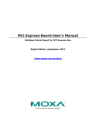
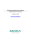
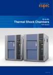
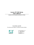
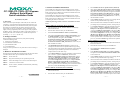
CP-132EL/CP-132EL-I PCI Express
Multiport Serial Board
Quick Installation Guide
First Edition, July 2008
1. Overview
Moxa’s new PCI Express multiport serial boards, the CP-132EL and
CP-132EL-I, are designed for POS and ATM applications and for use
by industrial automation system manufacturers and system integrators.
The boards are compatible with all popular operating systems and
support data rates of up to 921.6Kbps as well as full modem control
signals, ensuring compatibility with a wide range of serial peripherals.
In addition, the CP-132EL and CP-132EL-I work with PCI Express ×1,
allowing the boards to be installed in any available PCI Express slot
(including ×1, ×2, ×4, ×8, ×16, and ×32).
2. Package Checklist
4. Software Installation Information
3.
Select Install from a list or specific location (Advanced).
The board MUST be plugged in before installing the driver. See the
previous section for instructions on how to install the board in your PC.
Refer to the PCI Express Board User’s Manual for detailed instructions
on installing the drivers for this board.
4.
The board MUST be plugged in before installing the driver. See the
previous section for instructions on how to install the board in your PC.
Refer to the PCI Express Board User’s Manual for detailed instructions
on installing the drivers for this board.
After selecting Search for the best driver in these locations, select
the Include this location in the search, and then click Browse. If
the system is a 32-bit (x86) platform, navigate to the \CP-132EL
Series\Software\Windows XP_2003\x86 folder on the CD, if the
system is 64-bit (x64) platform, navigate to the \CP-132EL
Series\Software\Windows XP_2003\x64 folder on the CD, and
then click Next to continue.
5.
Click Continue Anyway in response to any warnings that the
software has not passed Windows Logo testing.
NOTE: The following procedure shows how to install the CP-132EL
driver.
6.
After the board has been installed, the installation wizard will guide
you through the port installation procedure, starting with port 0.
7.
Use the Device Manager to check the installation of the board and
ports. Click the + sign next to Hardware, and then check
Multi-port serial adapters and Ports (COM & LPT). Click the
+sign next to Multi-port serial adapters, right-click on Moxa
CP-132EL Series (PCI Express Bus), select Properties, then
choose Port Configuration. Click the port to configure Interface
(RS-422, 2-wire RS-485, 4-wire RS-485) and Termination
Resistor (120Ω, Enable or Disable). If there are warning marks,
such as a question mark or exclamation point in front of the board or
port icons, examine the Event Log to determine the problem.
Windows 2008/Vista (32-bit/64-bit) Driver Installation
1.
After powering on your PC, Windows 2008 will automatically
detect the PCIe board.
2.
Insert the PCIe software CD in your CD-ROM drive.
3.
Select Locate and install driver software (recommended).
4.
After selecting Search for driver software in this location, select
the Include subfolders, and then click Browse. If the system is a
32-bit (x86) platform, navigate to the \CP-132EL
Series\Software\Windows 2008_Vista\x86 folder on the CD, if the
system is 64-bit (x64) platform, navigate to the \CP-132EL
Series\Software\Windows 2008_Vista\x64 folder on the CD, and
then click Next to continue.
Before installing the PCI Express board, verify that the package
contains the following items:
y 1 PCI Express serial board
y Documentation and Software CD
y Quick Installation Guide
y Low Profile Bracket
Notify your sales representative if any of the above items is missing or
damaged.
5.
6.
After the board has been installed, the installation wizard will guide
you through the port installation procedure. Port installation is
complete when Port 0 has been set up.
7.
Use the Device Manager to check the installation of the board and
ports. Click the + sign next to Hardware, and then check
Multi-port serial adapters and Ports (COM & LPT). Click the
+sign next to Multi-port serial adapters, right-click on MOXA
CP-132EL Series (PCI Express Bus), select Properties, then
choose Port Configuration. Click the port to configure Interface
(RS-422, 2-wire RS-485, 4-wire RS-485) and Termination
Resistor (120Ω, Enable or Disable). If there are warning marks,
such as a question mark or exclamation point in front of the board or
port icons, examine the Event Log to determine the problem.
3. Hardware Installation Procedure
The PCI Express board MUST be plugged into the PC before the driver
is installed. Follow these steps to install the board in the PC.
STEP 1:
Power off the PC.
STEP 2:
Plug the board firmly into an open PCI Express slot.
STEP 3:
Fasten the holding screw to fix the control board in place.
STEP 4:
Connect the connection cable.
STEP 5:
Power on the PC; the BIOS will automatically set the IRQ
and I/O address.
Click Install this driver software anyway in response to any
warnings that the software has not passed Windows Logo testing.
Windows 2003/XP (32-bit/64-bit) Driver Installation
1.
After powering on your PC, Windows 2003/XP will automatically
detect the PCIe board.
2.
Insert the PCIe software CD in your CD-ROM drive.
P/N: 1802001320020
—1—
—2—
Windows 2000 Driver Installation
1.
After powering on your PC, Windows 2000 will automatically
detect the PCIe board.
2.
Insert the PCIe software CD in your CD-ROM drive.
3.
Select Search for a suitable driver for my device
(recommended).
4.
Under Optional search location, select specify a location.
Navigate to the \CP-132EL Series\Software\Windows 2K folder
on the software CD.
5.
Click Continue Anyway in response to any warnings that the
software has not passed Windows Logo testing.
6.
After the board has been installed, the installation wizard will guide
you through the port installation procedure, starting with port 0.
7.
Use the Device Manager to check the installation of the board and
ports. Click the + sign next to Hardware, and then check
Multi-port serial adapters and Ports (COM & LPT). Click the
+sign next to Multi-port serial adapters, right-click on MOXA
CP-132EL Series (PCI Express Bus), select Properties, then
choose Port Configuration. Click the port to configure Interface
(RS-422, 2-wire RS-485, 4-wire RS-485) and Termination
Resistor (120Ω, Enable or Disable). If there are warning marks,
such as a question mark or exclamation point in front of the board or
—3—
port icons, examine the Event Log to determine the problem.
Linux Driver Installation
assignments to facilitate making your own connection cable, and the
male DB9 device-side pin assignments for the optional
CBL-M25M9x2-50 cable.
1.
Female DB25: Board-side Pin Assignments
Execute the following commands from the Linux prompt:
#mount /dev/cdrom /mnt/cdrom
#cd /
#mkdir moxa
#cd /moxa
#cp /mnt/cdrom/<driver directory>/
driv_linux_smart_vx.x_build_yymmddhh.tgz .
#tar –xzvf driv_linux_smart_vx.x_build_yymmddhh.tgz
2.
#cd mxser
#make clean; make install
3.
#cd /moxa/mxser/driver
#./msmknod
4.
#modprobe mxupcie
5.
Use the Moxa Port Configuration Tool to set Interface and
Termination Resistor for the MUE series. The MUE series includes
CP-102E, CP-102EL, CP-132EL, CP-132EL-I, CP-114EL, and
CP-114EL-I.
Usage: muestty <operation> device
Device: The MUE series device node
Operation:
-h
Help
-g
Get interface and terminator type
-i intf
Set interface type with options below
-t value
Set termination resistor with options below
intf
RS422
RS-422 mode
RS4852W
RS-485 2-wire mode
RS4854W
RS-485 4-wire mode
value
NONTERM
Non termination resistor
120TERM
120ohm termination resistor
Port 1
12
8
24
Pin
For example:
To set the MUE interface
# muestty –i RS422 /dev/ttyMUE2
RS-422
P2: TxD-(A)
P2: SGND
--P2: TxD+(B)
--P1: RxD-(A)
----P1: RxD+(B)
--P2: RxD-(A)
----P2: RxD+(B)
P1: TxD-(A)
P1: SGND
--P1: TxD+(B)
2
3
4
5
8
9
10
11
12
14
15
16
17
18
21
22
23
24
21
5
2
18
14
Port 2
Transmission Signals
4-wire RS-485
2-wire RS-485
P2: TxD-(A)
----------P2: TxD+(B)
------P1: RxD-(A)
P1: Data-(A)
--------P1: RxD+(B)
P1: Data+(B)
----P2: RxD-(A)
P2: Data-(A)
--------P2: RxD+(B)
P2: Data+(B)
P1: TxD-(A)
----------P1: TxD+(B)
---
Male DB9 Connector: Device-side Pin Assignments
1
7
8
9
-------
-------
-------
6. Specifications
Hardware
Connectors
Comm. Controller
Interface
Bus Interface
Number of Ports
Max No. of Boards
Signal
RS-422
RS-485 4-Wire
RS-485 2-Wire
Performance
Baudrate
Configuration
Data Bits
Stop Bits
I/O address/IRQ
Parity
Flow Control
Environment
Operating Temperature
Operating Humidity
Storage Temperature
ESD Protection
Optical Isolation
Regulatory Approvals
Warranty
Female DB25
16C550C compatible
PCI Express × 1
2
4
TxD+(B), TxD-(A), RxD+(B), RxD-(A), GND
TxD+(B), TxD-(A), RxD+(B), RxD-(A), GND
Data+(B), Data-(A), GND
50 bps to 921.6 Kbps
5, 6, 7, 8
1, 1.5, 2
BIOS assigned
None, Even, Odd, Space, Mark
XON/XOFF
0 to 55°C (32 to 132°F)
5 to 95% RH
-20 to 85°C (-4 to 185°F)
Embedded 15 KV ESD Protection
2 KV (only for CP-132EL-I)
EN55022, EN55024, EN61000-3-2,
EN61000-3-3, EN61000-6-2, IEC-61000-4-2,
IEC 61000-4-3, IEC 61000-4-4, IEC
61000-4-5, IEC 61000-4-6, IEC 61000-4-8,
IEC 61000-4-11, FCC Part 15 Class B
5 years
5
To set the MUE termination resistor
# muestty –t 120TERM /dev/ttyMUE2
6.
Use the Moxa diagnostic utility to verify the driver status:
#cd /moxa/mxser/utility/diag
#./msdiag
7.
Use the Moxa terminal utility to test the tty ports:
#cd /moxa/mxser/utility/term
#./msterm
5. Pin Assignments
The CP-132EL and CP-132EL-I boards have a female DB25 connector
on the board. In this section, we give the on-board connector’s pin
—4—
6
Pin
1
2
3
4
5
6
RS-422
TxD-(A)
TxD+(B)
RxD+(B)
RxD-(A)
GND
---
9
Transmission Signals
4-wire RS-485 2-wire RS-485
TxD-(A)
--TxD+(B)
--RxD+(B)
Data+(B)
RxD-(A)
Data-(A)
GND
GND
-----
—5—
Click here for online support:
www.moxa.com/support
The Americas:
Europe:
Asia-Pacific:
China:
+1-714-528-6777 (toll-free: 1-888-669-2872)
+49-89-3 70 03 99-0
+886-2-8919-1230
+86-21-5258-9955 (toll-free: 800-820-5036)
© 2008 Moxa Inc., all rights reserved.
Reproduction without permission is prohibited.
—6—