1
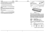
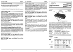
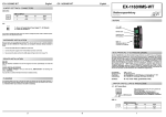
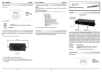
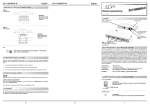
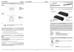
English
EX
EX--11069
English
EX
EX--11069
JUMPER SETTING & CONNECTORS:
J2 & J4:
Bedienungsanleitung
E-SATA :
Pin
Signal
Pin
Signal
1
GND
5
Receive -
2
Transmit +
6
Receive +
3
Transmit -
7
GND
4
GND
12 3 4 5 6 7
Vers. 1.0 / 09.10.09
AUFBAU :
J6 hinten:
Anschluss für
Stecker vom PCNetzteil
Attention!
Never plug in with force or in wrong direction.
J5:
+5VCC
Data1Data1+
GND
JP1
Stromquelle wählen
PCI oder AUX
J5
USB Anschluss
zum PC
USB 2.0 - 10 Pin :
1
3
5
7
9
2 +5VCC
4 Data26 Data2+
8 GND
10
Pin
Signal
Pin
Signal
Pin
1
VCC1 +5V
5
DATA1+
9
Signal
NC
2
VCC2 +5V
6
DATA2+
10
NC
3
DATA1-
7
GND1
4
DATA2-
8
GND2
Attention!!!:
Please make sure that you connect the cable in the right
order like shown in the list above. If you connect the cable
wrong it can destroy your hardware! The labelling on the
cable must match with the ones on our card.
J4
IDE Anschluss Pins
für SATA 1 & 2
J2 & J4:
2 x Externe USB 2.0 & SATA2
Kombianschlüsse
BESCHREIBUNG & TECHNISCHE DATEN :
HARDWARE INSTALLATION :
Die EX-11069 ist ein E-SATA & USB2 Combo Adapter für 2 Endgeräte. Er ist mit 2
USB2 & ESATA Kombi Ports für Endgeräte ausgestattet. Er unterstützt alle SATA
Chipsets und alle USB Chipsets. Die externe Stromversorgung wird über beiliegendes
Kabel via PC–Netzteil zur Verfügung gestellt. Der Adapter unterstützt optimal die Leistung des Host Adapters. Die EX-11069 gewährleistet so eine sichere Datenübertragung
und exzellente Performance von bis zu 300Mb pro Sekunde! Es ist nicht möglich die I/O
Adressen und Interrupts manuell einzustellen, da die Einstellungen vom System (BIOS)
und beim Installieren des Betriebssystems automatisch vorgenommen werden.
If you are ready with the jumper settings for the EX-11068 / 11068-L , please proceed with
the following installation instructions. Because the designs of computers are different, only
general installation instructions are given. Please refer your computer’s reference manual
whenever in doubt.
1. Turn off the power to your computer and any other connected peripherals.
2. Remove the mounting screws located at the rear and/or sides panels of your Computer and gently slide the cover off.
3. Locate an available slot and remove its covers from the rear panel of your computer.
4. Now connect the included USB & SATA cables with your mainboard or host card and
the other end with our card
5. If necessary please install now the external power supply to the card like shown at JP1
& J6 above.
Kompatibilität:
Betriebssysteme:
Anschlüsse:
Lieferumfang:
USB2.0 & SATA
Alle
2 x USB2.0 & ESATA Kombianschluss
EX-11069, CD, Anleitung, 10 Pin /SATA & Stromkabel,
Zertifikate:
CE / FCC / RoHS / WEEE
JP1:
7. Gently replace your computer’s cover and the mounting screws.
DRIVER INSTALLATION :
INT=PCI
AUX=AUX
JUMPER EINSTELLUNG & ANSCHLÜSSE:
6. Then connect the card with a screw to the rear panel of the computer.
Windows
INT = Strom vom PCI-Express BUS (Werkseinstellung)
AUX = Strom vom PC-Netzteil des Rechners
(Zur Entlastung des Mainboards und zur stabilen Stromversorgung bei
Verwendung von Endgeräten mit hohem Stromverbrauch).
Anschluss J6 muss mit PC-Netzteil verbunden werden!
After the hardware installation Windows will recognize the EX-11069 automatically. A
driver is not necessary because the EX-11069 will be connected to a host controller. If
there are any Problems with the installation please check the driver from your host
controller.
CHECK INSTALLED DRIVER:
Because this device doesn't use any driver it is not necessary to check the installation.
CLEANING :
For cleaning please use only a dry fluffless cloth and remove the dirt with gently pressure. In the area of the connectors please make sure that no fibres from the cloth remain in the connectors. Attention! Never use a moist or wet cloth for cleaning!
5
DE97424562 / WHQL
6
J6:
Wenn JP1 auf AUX gestellt ist muss J6 mit dem Strom vom PC Netzteil
verbunden werden! Bitte auf die richtige Polarität achten! Achtung!
Stecker nie bei eingeschaltetem PC ein oder ausstecken!
J2 & J4:
USB 2.0 A-Buchse:
Pin
Signal
Pin
Signal
1
VCC
4
GND
2
DATA-
3
DATA+
1
Deutsch
EX
EX--11069
J2 & J4:
Deutsch
EX
EX--11069
E-SATA :
Pin
Signal
Pin
Signal
1
GND
5
Receive -
2
Transmit +
6
Receive +
3
Transmit -
7
GND
4
GND
12 3 4 5 6 7
User Manual
Vers. 1.0 / 09.10.09
LAYOUT :
Attention!
Never plug in with force or in wrong direction.
J5:
J6 backside:
Connector for PC
power supply
USB 2.0 - 10 Pin :
+5VCC
Data1Data1+
GND
1
3
5
7
9
2 +5VCC
4 Data26 Data2+
8 GND
10
Pin
Signal
Pin
Signal
Pin
Signal
1
VCC1 +5V
5
DATA1+
9
NC
2
VCC2 +5V
6
DATA2+
10
NC
3
DATA1-
7
GND1
4
DATA2-
8
GND2
JP1
Change power source
PCI or AUX
J5
USB connector
to host PC
Achtung!!!:
Bitte achten sie darauf das die Kabel richtig verbunden
sind. Falsch angeschlossene Kabel können ihre Hardware
zerstören! Die Bezeichnungen der Kabel müssen mit
denen unserer Karte übereinstimmen.
J7
IDE Pins for
SATA 1 & 2
J2 & J4:
2 x External USB 2.0 & SATA2
Combo ports
HARDWARE INSTALLATION :
DESCRIPTION & TECNICAL INFORMATION :
Beachten Sie bitte die folgenden Installationshinweise. Da es grosse Unterschiede bei
Computern gibt, können wir Ihnen nur eine generelle Anleitung zum Einbau geben. Bei
Unklarheiten halten Sie sich bitte an die Bedienungsanleitung Ihres Computersystems.
The EX-11069 is a plug & play high-speed USB & SATA2 expansion adaptor. The EX11069 provides 2 external USB2.0 & SATA2 combo ports. It uses data transfer rates up
to 3Gbit/s. The EX-11069 design fully utilize the host adaptors chipset and supports the
latest USB interface technology. In combination with the host controller it provides a
secure and very high data transfer on each single port. It supports all USB2 And SATA
controllers. It is not possible to change the settings, they will be obtained automatically
via the system (BIOS) and operating system.
1.
Schalten Sie Ihren Rechner und alle angeschlossenen Peripheriegeräte aus und
ziehen Sie bei allen Geräten den Netzstecker.
2.
Lösen Sie die Schrauben des Gehäuses auf der Rückseite Ihres Computers und
entfernen Sie vorsichtig das Gehäuse.
3.
Verbinden sie nun die mitgelieferten SATA & USB Kabel mit ihrem Mainboard bzw.
Host Karte und unserer Karte. Folgen sie bitte der Installationsanweisung (siehe J5
oben). Sollte der Anschluss nicht beschriftet sein wenden sie sich bitte an den
Mainboard Hersteller.
Compatibility:
Operating system:
Connectors:
Lieferumfang:
USB2.0 & SATA
ALL
2 x ESATA & USB2.0 Combo port,
EX-11069, CD, manual, 10 Pin / SATA & power cable
4.
Gegebenenfalls installieren sie nun die externe Stromversorgung zur Entlastung des
Mainboards! (siehe Jumper Einstellung und Anschlüsse JP1 & J6)
Zertifikate:
CE / FCC / RoHS / WEEE
Suchen Sie jetzt einen freien Slot und befestigen sie die Karte mit einer Schraube.
6.
Jetzt können sie das Computergehäuse mit den Schrauben wieder schliessen.
JUMPER SETTING & CONNECTORS:
JP1:
TREIBER INSTALLATION :
Windows
Nach Abschluss der Hardware Installation erkennt Windows den EX-11069 automatisch. Ein Treiber ist nicht erforderlich da das Gerät an den Hostcontroller (SATA Karte
oder OnBoard Anschluss) angeschlossen wird. Sollte ein Problem bei der Installation
auftreten müssen sie eventuell ihren Host Controller neu Installieren oder dessen Treiber bzw. BIOS aktualisieren.
INT = Power from PCI-Express BUS (standard)
AUX = Power from PC power supply
(For safe direct power from pc power supply to provide sufficient power
for devices with high power consumption).
Connector J6 must be connected with PC power suplly!
ÜBERPRÜFEN DES INSTALLIERTEN TREIBER:
Eine Überprüfung der Installation entfällt da keine Treiber für das Gerät verwendet
werden.
REINIGUNG :
Zur Reinigung des Gerätes verwenden sie bitte ausschliesslich ein trockenes nicht
faserndes Tuch und entfernen sie die Verschmutzung mit leichtem Druck. Im Bereich
der Anschlüsse bitte darauf Achten dass keine Fasern des Tuchs in der Buchse verbleiben. Verwenden sie zu Reinigung in keinem Fall ein feuchtes oder nasses Tuch!
2
INT=PCI
AUX=AUX
5.
DE97424562 / WHQL
3
J6:
If JP1 is set to AUX J6 must be connected with pc power supply!
Please make sure you connect the plug in the right direction.
Never connect or release the plug while the PC power is on!
J2 & J4:
USB 2.0 A-Port:
Pin
Signal
Pin
Signal
1
VCC
4
GND
2
DATA-
3
DATA+
4