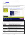
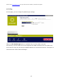
1
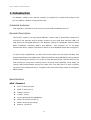
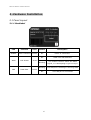
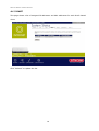
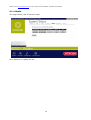
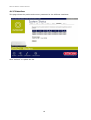
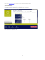
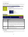
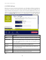
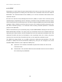
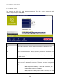
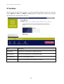
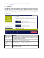
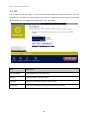
ADSL2+ Modem
DC-227
Full manual
Sitecom ADSL2+ Modem DC-227
Contents
1.
INTRODUCTION........................................................................................... 4
INTENDED AUDIENCE .................................................................................................4
GENERAL DESCRIPTION ..............................................................................................4
SPECIFICATIONS .......................................................................................................4
ADSL Standard ..................................................................................................4
Software Features ..............................................................................................5
Management .....................................................................................................5
2.
HARDWARE INSTALLATION......................................................................... 6
2.1 PANEL LAYOUT ....................................................................................................6
2.1.1 Top & frontpanel ........................................................................................6
2.1.2 Rear Panel ................................................................................................7
2.2 PROCEDURE FOR HARDWARE INSTALLATION..................................................................8
3
2.2.1
Hardware Requirements...........................................................................8
2.2.2
Decide where to place your ADSL2+ Modem...............................................8
2.2.3
Setup LAN connection..............................................................................8
2.2.4
Hardware Setup Procedures .....................................................................8
2.2.5
Power on ...............................................................................................8
NETWORK SETTINGS AND SOFTWARE INSTALLATION ................................... 9
3.1 ....................................................................................................................... 9
4
CONFIGURING THE ADSL2+ MODEM ............................................................. 10
4.1 START-UP AND LOG IN......................................................................................... 10
4.1.1 LAN Settings ........................................................................................... 12
4.1.2 ARP Settings ........................................................................................... 13
4.1.3 DHCP ..................................................................................................... 14
4.1.4 Route ..................................................................................................... 15
4.1.5 Interface................................................................................................. 16
4.1.6 Statistics ................................................................................................ 17
5
RUN SETUP WIZARD ..................................................................................... 18
6
BASIC SETTINGS ........................................................................................... 20
6.1 DNS SETTINGS ................................................................................................ 20
6.2 DHCP SETTINGS .............................................................................................. 21
6.2.1 DHCP Server ........................................................................................... 22
6.2.2 DHCP Relay Configuration ......................................................................... 23
2
Please check www.sitecom.com for up to date drivers & utilities, manuals and support
6.3 DDNS SETTINGS .............................................................................................. 24
6.4 IGMP............................................................................................................ 26
6.5 UPNP ............................................................................................................ 28
6.6 RIP .............................................................................................................. 29
7 FIREWALL SETTINGS ...................................................................................... 31
7.1 PORT FORWARDING ............................................................................................ 31
7.2 URL BLOCKING ................................................................................................ 33
7.3 DMZ............................................................................................................. 34
7.4 IP FILTERING ................................................................................................... 35
7.5 MAC FILTERING ................................................................................................ 37
7.6 REMOTE MANAGEMENT ........................................................................................ 39
8 ADVANCED SETTINGS ..................................................................................... 40
8.1 BRIDGING ....................................................................................................... 40
8.2 ROUTING ........................................................................................................ 41
8.3 SNMP ........................................................................................................... 43
8.4 QOS............................................................................................................. 45
8.5 MISC............................................................................................................. 47
8.6 ADSL SET ......................................................................................................48
8.7 ADSL ATM ..................................................................................................... 50
9 TOOLBOX ........................................................................................................ 52
9.1 TIMEZONE ....................................................................................................... 53
9.2 ACL.............................................................................................................. 54
9.3 FIRMWARE UPGRADE .......................................................................................... 55
9.4 BACKUP SETTINGS ............................................................................................. 56
9.5 COMMIT AND REBOOT ......................................................................................... 57
9.6 PING ............................................................................................................. 58
9.7 SYSLOG ......................................................................................................... 59
APPENDICES ...................................................................................................... 60
APPENDIX A: HOW TO MANUALLY FIND YOUR PC’S IP AND MAC ADDRESS ................................. 60
APPENDIX B: MAPPING PVCS TO VLANS ....................................................................... 61
3
Sitecom ADSL2+ Modem DC-227
1. Introduction
The ADSL2+ Modem user manual contains the guidance to install and configure the
DC-227 ADSL2+ Modem using the Web GUI.
Intended Audience
This manual is intended for end users to access ADSL broadband service.
General Description
The DC-227 modem is a high-speed ADSL2+ modem that is specifically designed to
connect to the Internet and to directly connect to your local area network (LAN) via
high-speed 10/100 Mbps Ethernet. The ADSL2+ modem is compatible with the latest
ADSL standards, including ADSL2 and ADSL2+, and supports up to 24 Mbps
downstream and 1.5 Mbps upstream to deliver true broadband speed and throughput.
To ensure fully compatibility, the DSL device was tested with all major DSLAMs, and
support standard 10/100 Mbps Base-T Ethernet interface Auto MDI/MDIx 10/100 Switch
function allowing user easily to link to PC or other Switches/Hubs. The DSL device is an
idea solution for multi-users utilizing build-in channel mode (PPPoE/A, IPoA, IPoE), IP
routing, NAT functionalities sharing the ADSL link. The DSL device is also a perfect
solution for the residential users, it supports the users with bridge mode in host based
PPPoE Client.
Specifications
ADSL Standard
ITU-T G.992.1(G.dmt)
ANSI T1.413 Issue 2
G.992.2 (G.lite)
G.994.1 (G.hs)
Auto-negotiating rate adaptation
ADSL2 G.dmt.bis (G.992.3)
ADSL2 G.lite.bis (G.992.4)
ADSL2+ (G.992.5)
4
Please check www.sitecom.com for up to date drivers & utilities, manuals and support
Software Features
RFC-1483/2684 LLC/VC-Mux bridged/routed mode
RFC-1577 Classical IP over ATM
RFC-2516 PPPoE
RFC-2364 PPPoA
ITU-T 1.610 F4/F5 OAM send and receive loop-back
802.1d Spanning-Tree Protocol
DHCP Client/Server/Relay
NAT
RIP v1/v2
DNS Relay Agent
DMZ support
IGMP Proxy/Snooping
Stateful Packet Inspection
Protection against Denial of Service attacks
IP Packet Filtering
QoS
Dynamic DNS
UPnP support
Management
Web-based Configuration
Menu-driven Command-line Interpreter
Telnet Remote Management
SNMP v1/v2/Trap
Firmware upgrade through FTP, TFTP and HTTP
Configuration backup/restore
5
Sitecom ADSL2+ Modem DC-227
2. Hardware Installation
2.1 Panel Layout
2.1.1 Backlabel
LED
Function
Color
Status
Description
POWER
Power indication
Green
On
Power is connected.
On
ADSL line was detected.
WAN
Link Status
Green
Blinking
LAN
Data Rate
The modem couldn’t detect the ADSL
signal, or is attempting to get line sync.
Blinking
The LAN port is sending or receiving data.
On
The LAN port is connected.
Green
6
Please check www.sitecom.com for up to date drivers & utilities, manuals and support
2.1.2 Rear Panel
Port
Description
WAN
The port to connect with your ADSL line.
Ethernet
The ports where you can connect your computer or other device.
Reset
To reset the system settings to factory defaults, press the reset button for at
least 10 seconds.
POWER
The power inlet.
7
Sitecom ADSL2+ Modem DC-227
2.2 Procedure for Hardware Installation
2.2.1
Hardware Requirements
•
ADSL/ADSL2/ADSL2+ Internet subscription
•
9V AC power adapter
•
RJ-45 Ethernet cable
•
RJ-11 ADSL line
2.2.2
Decide where to place your ADSL2+ Modem
You can place your ADSL2+ Modem on a desk or other flat surface, or you can mount it
on a wall. This location must be close to a power connection and your ADSL/Telephone
connection.
2.2.3
Setup LAN connection
Connect an Ethernet cable to one of your computers.
2.2.4
Hardware Setup Procedures
1. Connect the RJ-11 cable from the DC-227 to your ADSL line.
2. Connect the RJ-45 line from your PC to an Ethernet port on the DC-227.
3. Plug the power supply into a wall outlet.
2.2.5
Power on
Connect the power-adapter to the power inlet port and connect it to a wall outlet, this
product will automatically enter the self-test phase. When it is in the self-test phase, the
Power LED will not be lighted for about 15 seconds, and then Power will flash 9 times to
indicate that the self-test operation has finished. Finally, power will be lit continuously to
indicate that this product is in normal operation.
8
Please check www.sitecom.com for up to date drivers & utilities, manuals and support
3 Network Settings and Software Installation
3.1 Windows 2000/XP
1. Go to START > Configuration screen > (Network and Internet connections >) Network
connections.
2. Click on your network connection with the right hand mouse button and select
‘Properties’.
3. Click on ‘Internetprotocol (TCP/IP)’, and click on the button ‘Properties’.
4. Select ‘Obtain an IP address automatically’.
5. Click on OK, then on Close, and restart your PC.
3.2 Windows Vista
1.
2.
3.
4.
5.
6.
7.
Click the Windows (Start) button.
Right-click with the mouse on ‘Network’, and select ‘Properties’.
Click ‘status’ of your network connection, and select ‘Properties’ in the new window.
In User Account Control click ‘continue’.
Click ‘Internet Protocol Version 4 (TCP/IPv4)’, then click ‘Properties’.
Select ‘Obtain an IP address automatically’.
Click OK, then close all windows and restart your PC.
9
Sitecom ADSL2+ Modem DC-227
4
Configuring the ADSL2+ Modem
This ADSL2+ Modem uses a easy-setup web-interface which can be opened through your
webbrowser, such as Netscape Communicator or Internet Explorer. This approach can be
adopted in any MS Windows, Macintosh or UNIX based platforms.
The default configurations for the system are listed below.
•
LAN IP address: 10.0.0.1
Subnet Mask:
255.255.255.0
•
VPI/VCI:
Encapsulation:
1483 Bridged IP LLC
admin,
Password:
admin
user,
Password:
user
8/35,
[Administrator Login]
•
Username:
[User Login]
•
Username:
4.1 Start-up and Log in
1. Start your web browser (e.g. Internet Explorer).
2. Type in de address bar:
http://10.0.0.1, and press [Enter].
3. Enter your username as: admin, and for your password: admin, and click OK.
4. You will now see the start page for your modem.
10
Please check www.sitecom.com for up to date drivers & utilities, manuals and support
The Status section allows you to monitor the current status of your modem. You can use the
Status page to monitor; the connection status of the ADSL modem's WAN/LAN interfaces,
the current firmware and hardware version numbers, and information on all DHCP client PCs
currently connected to your network.
Connect / Disconnect
The two buttons take effect only when PVC is configured as PPPoE/PPPoA mode.
Click Connect/Disconnect button to connect/disconnect the PPP dial up link.
11
Sitecom ADSL2+ Modem DC-227
4.1.1 LAN Settings
This page shows the current setting of LAN interface. You can set IP address, subnet mask,
and IGMP Snooping for LAN interface in this page.
Fields on this page:
Field
Description
IP Address
The IP address your LAN hosts uses to identify the device’s LAN port.
Subnet Mask
LAN subnet mask.
IGMP Snooping
Enable/disable the IGMP snooping function for the multiple bridged LAN
ports.
Apply Changes
Click to save the setting to the configuration. New parameters will take effect after save
into flash memory and reboot the system.
Undo
Discard your changes.
12
Please check www.sitecom.com for up to date drivers & utilities, manuals and support
4.1.2 ARP Settings
This page shows a list of MAC addresses and IP addresses for devices that are/were
connected to the ADSL modem.
Click “Refresh” to update the list.
13
Sitecom ADSL2+ Modem DC-227
4.1.3 DHCP
This page shows a list of assigned IP addresses and MAC addresses for each DHCP leased
client.
Click “Refresh” to update the list.
14
Please check www.sitecom.com for up to date drivers & utilities, manuals and support
4.1.4 Route
This page shows a list of learned routes.
Click “Refresh” to update the list.
15
Sitecom ADSL2+ Modem DC-227
4.1.5 Interface
This page shows the packet and memory statistics for the different interfaces.
Click “Refresh” to update the list.
16
Please check www.sitecom.com for up to date drivers & utilities, manuals and support
4.1.6 Statistics
This page shows the statistics for the ADSL line and connection.
Click “Refresh” to update the list.
17
Sitecom ADSL2+ Modem DC-227
5
Run Setup Wizard
•
Click Wizard to configure the modem.
•
The Setup wizard will now be displayed; check that the modem is connected and
click Next.
•
Select your country from the Country list.
•
From Service, select your internet provider. Click Next.
•
Depending on the chosen provider, you may need to enter your user name and
password, or MAC address in the following window. After you have entered the correct
information, click Next.
•
Click APPLY to complete the configuration.
18
Please check www.sitecom.com for up to date drivers & utilities, manuals and support
•
The modem will now save the settings and restart, please wait 120 seconds and you
will be transferred back to the status window. The configuration is complete.
•
Wait for about 10 seconds to allow the modem to (re)connect to the Internet.
19
Sitecom ADSL2+ Modem DC-227
6
Basic Settings
6.1 DNS Settings
This page is used to select the way to obtain the IP addresses of the DNS servers.
Field
Description
Attain DNS
Select this item if you want to use the DNS servers obtained by the WAN
Automatically
interface via the auto-configuration mechanism.
Set DNS Manually
Select this item to configure up to three DNS IP addresses.
Apply Changes
Set new DNS relay configuration. New parameters will take effect after save into flash
memory and reboot the system.
Undo
Discard your changes.
20
Please check www.sitecom.com for up to date drivers & utilities, manuals and support
6.2 DHCP Settings
You can configure your network and DSL device to use the Dynamic Host Configuration
Protocol (DHCP). This page provides DHCP instructions for implementing it on your network
by selecting the role of DHCP protocol that this device wants to play. There are two different
DHCP roles that this device can act as: DHCP Server and DHCP Relay. When acting as DHCP
server, you can setup the server parameters at the DHCP Server page; while acting as DHCP
Relay, you can setup the relay at the DHCP Relay page.
21
Sitecom ADSL2+ Modem DC-227
6.2.1 DHCP Server
By default, the device is configured as a DHCP server, with a predefined IP address pool of
192.168.0.100 through 192.168.0.200 (subnet mask 255.255.255.0).
Field
Description
IP Pool Range
Specify the lowest and highest addresses in the pool.
Max Lease Time
The Lease Time is the amount of time that a network user is allowed to
maintain a network connection to the device using the current dynamic
IP address. At the end of the Lease Time, the lease is either renewed or
a new IP is issued by the DHCP server. The amount of time is in units of
seconds. The default value is 86400 seconds (1 day). The value –1
stands for the infinite lease.
Domain Name
A user-friendly name that refers to the group of hosts (subnet) that will
be assigned addresses from this pool.
Apply Changes
Set new DHCP server configuration. New parameters will take effect after saving into
flash memory and rebooting the system.
22
Please check www.sitecom.com for up to date drivers & utilities, manuals and support
6.2.2 DHCP Relay Configuration
Some ISPs perform the DHCP server function for their customers’ home/small office network.
In this case, you can configure this device to act as a DHCP relay agent. When a host on your
network requests Internet access, the device contacts your ISP to obtain the IP configuration,
and then forward that information to the host.
Field
Description
DHCP Server
Specify the IP address of your ISP’s DHCP server. Requests for IP
Address
information from your LAN will be passed to the default gateway, which
should route the request appropriately.
Apply Changes
Click to save the setting to the configuration. New parameters will take effect after
saving into flash memory and rebooting the system.
23
Sitecom ADSL2+ Modem DC-227
6.3 DDNS Settings
Each time your device connects to the Internet, your ISP assigns a different IP address to
your device. In order for you or other users to access your device from the WAN-side, you
need to manually track the IP that is currently used. The Dynamic DNS feature allow you to
register your device with a DNS server and access your device each time using the same host
name. The Dynamic DNS page allows you to enable/disable the Dynamic DNS feature.
Field
Description
Enable
Check this item to enable this registration account for the DNS server.
DDNS provider
There are two DDNS providers to be selected in order to register your
device with: DynDNS and TZO. A charge may occurs depends on the
service you select.
Hostname
Domain name to be registered with the DDNS server.
Interface
This field defaults to your device’s WAN interface over which your
device will be accessed.
Username
User-name assigned by the DDNS service provider.
Password
Password assigned by the DDNS service provider.
Add
24
Please check www.sitecom.com for up to date drivers & utilities, manuals and support
Click Add to add this registration into the configuration.
Remove
Select an existing DDNS registration by clicking the radio button at the Select column of
the Dynamic DNS Table. Click Remove button to remove the selected registration
from the configuration.
Apply Changes
Set new DNS relay configuration. New parameters will take effect after save into flash
memory and reboot the system.
Undo
Discard your changes.
25
Sitecom ADSL2+ Modem DC-227
6.4 IGMP
Multicasting is useful when the same data needs to be sent to more than one hosts. Using
multicasting as opposed to sending the same data to the individual hosts uses less network
bandwidth. The multicast feature also enables you to receive multicast video stream from
multicast servers.
IP hosts use Internet Group Management Protocol (IGMP) to report their multicast group
memberships to neighboring routers. Similarly, multicast routers use IGMP to discover which
of their hosts belong to multicast groups. This device supports IGMP proxy that handles IGMP
messages. When enabled, this device acts as a proxy for a LAN host making requests to join
and leave multicast groups, or a multicast router sending multicast packets to multicast
group on the WAN side.
When a host wishes to join a multicast group, it sends IGMP REPORT message to the device’s
IGMP downstream interface. The proxy sets up a multicast route for the interface and host
requesting the video content. It then forwards the Join to the upstream multicast router. The
multicast IP traffic will then be forwarded to the requesting host. On a leave, the proxy
removes the route and then forwards the leave to the upstream multicast router.
The IGMP Proxy page allows you to enable multicast on WAN and LAN interfaces. The LAN
interface is always served as downstream IGMP proxy, and you can configure one of the
available WAN interfaces as the upstream IGMP proxy.
Upstream: The interface that IGMP requests from hosts are sent to the
multicast router.
Downstream: The interface data from the multicast router are sent to hosts in
the multicast group database.
26
Please check www.sitecom.com for up to date drivers & utilities, manuals and support
Field
Description
IGMP Proxy
Enable/disable IGMP proxy feature
Proxy Interface
The upstream WAN interface is selected here.
Apply Changes
Click to save the setting to the configuration.
Undo
Discard your settings.
27
Sitecom ADSL2+ Modem DC-227
6.5 UPnP
The DSL device supports a control point for Universal Plug and Play (UPnP) version 1.0, and
supports two key features: NAT Traversal and Device Identification. This feature
requires one active WAN interface. In addition, the host should support this feature. In the
presence of multiple WAN interfaces, select an interface on which the incoming traffic is
present.
With NAT Traversal, when an UPnP command is received to open ports in NAT, the application
translates the request into system commands to open the ports in NAT and the firewall. The
interface to open the ports on is given to UPnP when it starts up and is part of the
configuration of the application.
For Device Identification, the application will send a description of the DSL device as a control
point back to the host making the request.
Field
Description
UPnP Daemon
Enable/disable UPnP feature.
Binded WAN
Select WAN interface that will use UPnP from the drop-down lists.
Interface
Apply Changes
28
Please check www.sitecom.com for up to date drivers & utilities, manuals and support
Click to save the setting to the system configuration.
6.6 RIP
RIP is an Internet protocol you can set up to share routing table information with other
routing devices on your LAN, at your ISP’s location, or on remote networks connected to your
network via the ADSL line.
Most small home or office networks do not need to use RIP; they have only one router, such
as the ADSL Modem, and one path to an ISP. In these cases, there is no need to share routes,
because all Internet data from the network is sent to the same ISP gateway.
You may want to configure RIP if any of the following circumstances apply to your network:
−
Your home network setup includes an additional router or RIP-enabled PC
(other than the ADSL Modem). The ADSL Modem and the router will need to
communicate via RIP to share their routing tables.
−
Your network connects via the ADSL line to a remote network, such as a
corporate network. In order for your LAN to learn the routes used within your
corporate network, they should both be configured with RIP.
−
Your ISP requests that you run RIP for communication with devices on their
network.
29
Sitecom ADSL2+ Modem DC-227
Field
Description
RIP
Enable/disable RIP feature.
Field
Description
Interface
The name of the interface on which you want to enable RIP.
Receive Mode
Indicate the RIP version in which information must be passed to the DSL
device in order for it to be accepted into its routing table.
Send Mode
Indicate the RIP version this interface will use when it sends its route
information to other devices.
Add
Add a RIP entry and the new RIP entry will be display in the table
Delete Selected Entry
Delete a selected RIP entry. The RIP entry can be selected on the Select column of the
RIP Config Table.
Apply Changes
Set new DHCP server configuration. New parameters will take effect after saving into
flash memory and rebooting the system.
30
Please check www.sitecom.com for up to date drivers & utilities, manuals and support
7 Firewall Settings
Firewall contains several features that are used to deny or allow traffic from passing through
the device.
7.1 Port Forwarding
Firewall keeps unwanted traffic from the Internet away from your LAN computers. Add a Port
Forwarding entry will create a tunnel through your firewall so that the computers on the
Internet can communicate to one of the computers on your LAN on a single port.
Field
Description
Enable Port
Check this item to enable the port-forwarding feature.
Forwarding
Protocol
There are 3 options available: TCP, UDP and Both.
Enable
Check this item to enable this entry.
Local IP Address
IP address of your local server that will be accessed by Internet.
Port
The destination port number that is made open for this application on
the LAN-side.
31
Sitecom ADSL2+ Modem DC-227
Remote IP Address The source IP address from which the incoming traffic is allowed. Leave
blank for all.
External Port
The destination port number that is made open for this application on
the WAN-side
Interface
Select the WAN interface on which the port-forwarding rule is to be
applied.
Apply Changes
Click to save the rule entry to the configuration.
Delete Selected
Delete the selected port forwarding rules from the forwarding table. You can click the
checkbox at the Select column to select the forwarding rule.
Delete All
Delete all forwarding rules from the forwarding table.
32
Please check www.sitecom.com for up to date drivers & utilities, manuals and support
7.2 URL Blocking
The URL Blocking is the web filtering solution. The firewall includes the ability to block access
to specific web URLs based on string matches. This can allow large numbers of URLs to be
blocked by specifying only a FQDN (such as tw.yahoo.com). The URL Blocking enforce a Web
usage policy to control content downloaded from, and uploaded to, the Web.
Field
Description
URL Blocking
Check this item to enable the URL Blocking feature.
capability
FQDN
A fully qualified domain name (or FQDN) is an unambiguous domain
name that specifies the node's position in the DNS tree hierarchy
absolutely, such as tw.yahoo.com. The FQDN will be blocked to access.
Keyword
The filtered keyword such as yahoo. If the URL includes this keyword,
the URL will be blocked to access.
Apply Changes:
Click to disable/enable the URL Blocking capability
Add FQDN:
Add FQDN into URL Blocking table.
Delete Selected FQDN:
Delete the selected FQDN from the URL Blocking table. You can
click the checkbox at the Select column to select the Blocked
FQDN.
33
Sitecom ADSL2+ Modem DC-227
7.3 DMZ
A DMZ (Demilitarized Zone) allows a single computer on your LAN to expose ALL of its ports
to the Internet. Enter the IP address of that computer as a DMZ (Demilitarized Zone) host
with unrestricted Internet access. When doing this, the DMZ host is no longer behind the
firewall.
Field
Description
Enable DMZ
Check this item to enable the DMZ feature.
DMZ Host IP
IP address of the local host. This feature sets a local host to be exposed
Address
to the Internet.
Apply Changes
Click to save the setting to the configuration.
34
Please check www.sitecom.com for up to date drivers & utilities, manuals and support
7.4 IP Filtering
The IP/Port filtering feature allows you to deny/allow specific services or applications in the
forwarding path.
Field
Description
Outgoing Default
Specify the default action on the LAN to WAN forwarding path.
Action
Incoming Default
Specify the default action on the WAN to LAN forwarding path.
Action
Apply Changes
Click to save the setting of default actions to the configuration.
35
Sitecom ADSL2+ Modem DC-227
Field
Description
Rule Action
Deny or allow traffic when matching this rule.
Direction
Traffic forwarding direction.
Protocol
There are 3 options available: TCP, UDP and ICMP.
Src IP Address
The source IP address assigned to the traffic on which filtering is
applied.
Src Subnet Mask
Subnet-mask of the source IP.
Src Port
Starting and ending source port numbers.
Dst IP Address
The destination IP address assigned to the traffic on which filtering is
applied.
Dst Subnet Mask
Subnet-mask of the destination IP.
Dst Port
Starting and ending destination port numbers.
Apply Changes
Click to save the rule entry to the configuration.
Delete Selected
Delete selected filtering rules from the filter table. You can click the checkbox at the
Select column to select the filtering rule.
Delete All
Delete all filtering rules from the filter table.
36
Please check www.sitecom.com for up to date drivers & utilities, manuals and support
7.5 MAC Filtering
The MAC filtering feature allows you to define rules to allow or deny frames through the
device based on source MAC address, destination MAC address, and traffic direction.
Field
Description
Outgoing Default
Specify the default action on the LAN to WAN bridging/forwarding path.
Action
Incoming Default
Specify the default action on the WAN to LAN bridging/forwarding path.
Action
Rule Action
Deny or allow traffic when matching this rule.
Direction
Traffic bridging/forwarding direction.
Src MAC Address
he source MAC address. It must be xxxxxxxxxxxx format. Blanks can be
used in the MAC address space and are considered as don’t care.
Dst MAC Address
The destination MAC address. It must be xxxxxxxxxxxx format. Blanks
can be used in the MAC address space and are considered as don’t care.
37
Sitecom ADSL2+ Modem DC-227
Apply Changes
Click to save the rule entry to the configuration.
Delete Selected
Delete selected filtering rules from the filter table. You can click the checkbox at the
Select column to select the filtering rule.
Delete All
Delete all filtering rules from the filter table.
38
Please check www.sitecom.com for up to date drivers & utilities, manuals and support
7.6 Remote Management
The Remote Access function can secure remote host access to your DSL device from LAN and
WLAN interfaces for some services provided by the DSL device.
Field
Description
LAN
Check/un-check the services on the LAN column to allow/un-allow the
services access from LAN side; and “WAN”:
WAN
Check/un-check the services on the WAN column to allow/un-allow the
services access from WAN side.
WAN Port
This field allows the user to specify the port of the corresponding
service. Take the HTTP service for example; when it is changed to 8080,
the HTTP server address for the WAN side is http://dsl_addr:8080,
where the dsl_addr is the WAN side IP address of the DSL device.
39
Sitecom ADSL2+ Modem DC-227
8 Advanced Settings
8.1 Bridging
You can enable/disable Spanning Tree Protocol and set MAC address aging time in this
page.
Field
Description
Ageing Time
Set the Ethernet address ageing time, in seconds. After [Ageing Time]
seconds of not having seen a frame coming from a certain address, the
bridge will time out (delete) that address from Forwarding DataBase
(fdb).
802.1d Spanning
Enable/disable the spanning tree protocol
Tree
Apply Changes
Save this bridge configuration. New configuration will take effect after saving into flash
memory and rebooting the system.
Show MACs
List MAC address in forwarding table.
40
Please check www.sitecom.com for up to date drivers & utilities, manuals and support
8.2 Routing
The Routing page enables you to define specific route for your Internet and network data.
Most users do not need to define routes. On a typical small home or office LAN, the existing
routes that set up the default gateways for your LAN hosts and for the DSL device provide the
most appropriate path for all your Internet traffic.
−
On your LAN hosts, a default gateway directs all Internet traffic to the LAN
port(s) on the DSL device. Your LAN hosts know their default gateway either
because you assigned it to them when you modified your TCP/IP properties, or
because you configured them to receive the information dynamically from a
server whenever they access the Internet.
−
On the DSL device itself, a default gateway is defined to direct all outbound
Internet traffic to a route at your ISP. The default gateway is assigned either
automatically by your ISP whenever the device negotiates an Internet access,
or manually by user to setup through the configuration.
You may need to define routes if your home setup includes two or more networks or subnets,
if you connect to two or more ISP services, or if you connect to a remote corporate LAN.
Field
Description
Enable
Check to enable the selected route or route to be added.
Destination
The network IP address of the subnet. The destination can be specified
41
Sitecom ADSL2+ Modem DC-227
as the IP address of a subnet or a specific host in the subnet. It can also
be specified as all zeros to indicate that this route should be used for all
destinations for which no other route is defined (this is the route that
creates the default gateway).
Subnet Mask
The network mask of the destination subnet. The default gateway uses
a mask of 0.0.0.0.
Next Hop
The IP address of the next hop through which traffic will flow towards
the destination subnet.
Metric
Defines the number of hops between network nodes that data packets
travel. The default value is 0, which means that the subnet is directly
one hop away on the local LAN network.
Interface
The WAN interface to which a static routing subnet is to be applied.
Add Route
Add a user-defined destination route.
Update
Update the selected destination route on the Static Route Table.
Delete Selected
Delete a selected destination route on the Static Route Table.
Show Routes
Click this button to view the DSL device’s routing table. The IP Route Table displays, as
shown in Figure.
42
Please check www.sitecom.com for up to date drivers & utilities, manuals and support
8.3 SNMP
Simple Network Management Protocol (SNMP) is a troubleshooting and management
protocol that uses the UDP protocol on port 161 to communicate between clients and servers.
The DSL device can be managed locally or remotely by SNMP protocol.
Field
Description
System Description System description of the DSL device.
System Contact
Contact person and/or contact information for the DSL device.
System Name
An administratively assigned name for the DSL device.
System Location
The physical location of the DSL device.
System Object ID
Vendor object identifier. The vendor’s authoritative identification of the
network management subsystem contained in the entity.
Trap IP Address
Destination IP address of the SNMP trap.
Community name
Name of the read-only community. This read-only community allows
(read-only)
read operation to all objects in the MIB.
Community name
Name of the write-only community. This write-only community allows
(write-only)
write operation to the objects defines as read-writable in the MIB.
43
Sitecom ADSL2+ Modem DC-227
Apply Changes
Save SNMP configuration. New configuration will take effect after saving into flash
memory and rebooting the system.
44
Please check www.sitecom.com for up to date drivers & utilities, manuals and support
8.4 QOS
The DSL device provides a control mechanism that can provide different priority to different
users or data flows. The QoS is enforced by the QoS rules in the QoS table. A QoS rule
contains two configuration blocks: Traffic Classification and Action. The Traffic
Classification enables you to classify packets on the basis of various fields in the packet and
perhaps the physical ingress port. The Action enables you to assign the strictly priority level
for and mark some fields in the packet that matches the Traffic Classification rule. You can
configure any or all field as needed in these two QoS blocks for a QoS rule.
Field
Description
IP QoS
Enable/disable the IP QoS function.
Source IP
The IP address of the traffic source.
Source Netmask
The source IP netmask. This field is required if the source IP has been
entered.
Destination IP
The IP address of the traffic destination.
Destination
The destination IP netmask. This field is required if the destination IP
Netmask
has been entered.
Protocol
The selections are TCP, UDP, ICMP and the blank for none. This field is
45
Sitecom ADSL2+ Modem DC-227
required if the source port or destination port has been entered.
Source Port
The source port of the selected protocol. You cannot configure this field
without entering the protocol first.
Destination Port
The destination port of the selected protocol. You cannot configure this
field without entering the protocol first.
Physical Port
The incoming ports. The selections include LAN ports, wireless port, and
the blank for not applicable.
Field
Description
Outbound Priority
The priority level for the traffic that matches this classification rule. The
possible selections are (in the descending priority): p0, p1, p2, p3.
IP Precedence
Select this field to mark the IP precedence bits in the packet that match
this classification rule.
IP Type of Service
Select this field to mark the IP TOS bits in the packet that match this
classification rule.
802.1p
Select this field to mark the 3-bit user-priority field in the 802.1p
header of the packet that match this classification rule. Note that this
802.1p marking is workable on a given PVC channel only if the VLAN tag
is enabled in this PVC channel.
46
Please check www.sitecom.com for up to date drivers & utilities, manuals and support
8.5 Misc
On this page, you can change IP passthrough settings.
When the IP Passthrough option is enabled, only one PC is able to access
the Internet, and the DHCP server will duplicate the WAN IP address from the ISP to the
local client PC. Only the PC with the WAN IP address can access the Internet. This option is
sometimes also called “PPP Half-Bridge”.
47
Sitecom ADSL2+ Modem DC-227
8.6 ADSL Set
The ADSL setting page allows you to select any combination of DSL training
modes.
Field
Description
ADSL modulation
Choose prefered xdsl standard protocols.
G.lite : G.992.2 Annex A
G.dmt : G.992.1 Annex A
T1.413 : T1.413 issue #2
ADSL2 : G.992.3 Annex A
ADSL2+ : G.992.5 Annex A
AnnexL Option
Enable/Disable ADSL2/ADSL2+ Annex L capability.
AnnexM Option
Enable/Disable ADSL2/ADSL2+ Annex M capability.
ADSL Capability
“Bitswap Enable” : Enable/Disable bitswap capability.
“SRA Enable” : Enable/Disable SRA (seamless rate adaptation)
capability.
Tone Mask
48
Please check www.sitecom.com for up to date drivers & utilities, manuals and support
Choose tones to be masked. Mased tones will not carry any data.
Apply Changes
Click to save the setting to the configuration and the modem will be retrained.
49
Sitecom ADSL2+ Modem DC-227
8.7 ADSL ATM
The page is for ATM PVC QoS parameters setting. The DSL device support 4 QoS
mode —CBR/rt-VBR/nrt-VBR/UBR.
Field
Description
VPI
Virtual Path Identifier. This is read-only field and is selected on the
Select column in the Current ATM VC Table.
VCI
Virtual Channel Identifier. This is read-only field and is selected on the
Select column in the Current ATM VC Table. The VCI, together with VPI,
is used to identify the next destination of a cell as it passes through to
the ATM switch.
QoS
Quality of Server, a characteristic of data transmission that measures
how accurately and how quickly a message or data is transferred from a
source host to a destination host over a network. The four QoS options
are:
−
UBR (Unspecified Bit Rate): When UBR is selected, the
SCR and MBS fields are disabled.
−
CBR (Constant Bit Rate): When CBR is selected, the SCR
and MBS fields are disabled.
50
Please check www.sitecom.com for up to date drivers & utilities, manuals and support
−
nrt-VBR (non-real-time Variable Bit Rate): When nrt-VBR
is selected, the SCR and MBS fields are enabled.
−
rt-VBR (real-time Variable Bit Rate): When rt-VBR is
selected, the SCR and MBS fields are enabled.
PCR
Peak Cell Rate, measured in cells/sec., is the cell rate which the source
may never exceed.
SCR
Sustained Cell Rate, measured in cells/sec., is the average cell rate over
the duration of the connection.
MBS
Maximum Burst Size, a traffic parameter that specifies the maximum
number of cells that can be transmitted at the peak cell rate.
Apply Changes
Set new PVC OoS mode for the selected PVC. New parameters will take effect after save
into flash memory and reboot the system.
Undo
Discard your settings.
51
Sitecom ADSL2+ Modem DC-227
9 Toolbox
The first time you log into the system, you use the default password. There are two-level
logins: admin and user. The admin and user password configuration allows you to change
the password for administrator and user.
Field
Description
User Name
Selection of user levels are: admin and user.
Old Password
Enter the old password for this selected login.
New Password
Enter the new password here.
Confirmed Password Enter the new password here again to confirm.
52
Please check www.sitecom.com for up to date drivers & utilities, manuals and support
9.1 Timezone
Simple Network Timing Protocol (SNTP) is a protocol used to synchronize the system time to
the public SNTP servers. The DSL device supports SNTP client functionality in compliance
with IETF RFC2030. SNTP client functioning in daemon mode which issues sending client
requests to the configured SNTP server addresses periodically can configure the system clock
in the DSL device.
Field
Description
Current Time
The current time of the specified time zone. You can set the current time
by yourself or configured by SNTP.
Time Zone Select
The time zone in which the DSL device resides.
Enable SNTP client
Enable the SNTP client to update the system clock.
update
SNTP server
The IP address or the host name of the SNTP server. You can select from
the list or set it manually.
53
Sitecom ADSL2+ Modem DC-227
9.2 ACL
The Access Control List (ACL) is a list of permissions attached to the DSL device. The list
specifies who is allowed to access this device. If ACL is enabled, all hosts cannot access this
device except for the hosts with IP address in the ACL table.
Field
Description
ACL Capability
Enable/disable the ACL function
Enable
Check to enable this ACL entry
Interface
Select the interface domain: LAN or WAN
IP Address
Enter the IP address that allow access to this device.
54
Please check www.sitecom.com for up to date drivers & utilities, manuals and support
9.3 Firmware Upgrade
This page allows you to upgrade the modem’s firmware.
To upgrade the firmware for the DSL device:
−
Click the Browse button to select the firmware file.
−
Confirm your selection.
−
Click the Upload button to start upgrading.
IMPORTANT! Do not turn off your DSL device or press the Reset button while this procedure
is in progress.
IMPORTANT! Make sure you use a wired client to upgrade the firmwqare from. Disable your
wireless network card to prevent possible damage due to incomplete upgrading.
55
Sitecom ADSL2+ Modem DC-227
9.4 Backup Settings
The Backup screen allows you to save (Backup) the modem’s current configuration settings.
When you save the configuration setting (Backup) you can re-load the saved configuration
into the modem through the Restore selection. If extreme problems occur you can use the
Restore to Factory Defaults selection, this will set all configurations to its original default
settings (e.g. when you first purchased the modem).
Use the "Backup" tool to save the Broadband modem current configuration to a file named
"config.bin" on your PC. You can then use the "Restore" tool to restore the saved
configuration to the Broadband modem. Alternatively, you can use the "Restore to Factory
Defaults" tool to force the Broadband modem to perform a power reset and restore the
original factory settings.
56
Please check www.sitecom.com for up to date drivers & utilities, manuals and support
9.5 Commit and reboot
Whenever you use the Web configuration to change system settings, the changes are initially
placed in temporary storage. These changes will be lost if the device is reset or turn off. To
save your change for future use, you can use the commit function.
Commit and Reboot
Whenever you use the web console to change system settings, the changes are initially
placed in temporary storage. To save your changes for future use, you can use the
Commit/Reboot function. This function saves your changes from RAM to flash memory
and reboot the system.
IMPORTANT! Do not turn off your modem or press the Reset button while this procedure is
in progress.
57
Sitecom ADSL2+ Modem DC-227
9.6 Ping
Once you have your DSL device configured, it is a good idea to make sure you can ping the
network. A ping command sends a message to the host you specify. If the host receives the
message, it sends messages in reply. To use it, you must know the IP address of the host you
are trying to communicate with and enter the IP address in the Host Address field. Click Go!
To start the ping command, the ping result will then be shown in this page.
Field
Description
Host Address
The IP address you want to ping.
58
Please check www.sitecom.com for up to date drivers & utilities, manuals and support
9.7 Syslog
This page allows you to enable or disable the system log.
59
Sitecom ADSL2+ Modem DC-227
Appendices
Appendix A: How to manually find your PC’s IP and MAC address
1) In Window’s open the Command Prompt program
2) Type ipconfig /all and <enter>
•
Your PC’s IP address is the one entitled IP address (e.g. 192.168.0.100)
•
The modem’s IP address is the one entitled Default Gateway (e.g. 192.168.0.1)
•
Your PC’s MAC Address is the one entitled Physical Address (e.g.
00-13-D3-33-8D-45)
60
Please check www.sitecom.com for up to date drivers & utilities, manuals and support
Appendix B: Mapping PVCs to VLANs
RTL867x device supports mapping ATM Permanent Virtual Circuits (PVCs) to VLANs, based
on the ATM bridging standards of RFC 2684. This feature allows an ATM PVC to be configured
as a bridging interface and used in conjunction with a VLAN. The function is supported only
if the device is equipped with a RTL8205SC, which is a 5-port 10/100MBps switch controller.
Figure B.1 illustrates the how the RTL867x device adds a VLAN ID and tag to packets subject
to PVC-VLAN mapping. In this example, vc3 is mapped to VLAN 20. The RTL867x device adds
VLAN ID 20 and tag 8100 to packets from vc3.
ATM
RTL8670
Vc3
Ethern
Heade
IP
Heade
DATA
device
RTL867x
Vc3 mapped to VLAN 20
Ethern
Heade
VLAN ID
20
Tag
0x810
Ethern
Heade
IP
Heade
DATA
IP
Heade
RTL8305S
VLAN
VLAN
Figure B.1 Adding a VLAN ID and tag to packets
61
DATA