1
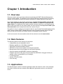
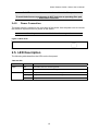
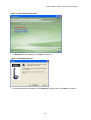
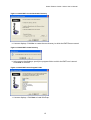
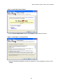
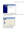
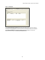
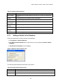
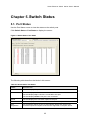
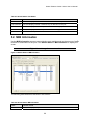
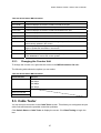
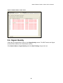
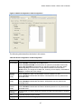
Smart Ethernet
Switch Series
User’s Manual
Smart Ethernet Switch Series User’s Manual
Table of Contents
Table of Contents .................................................................................................................................. 1
List of Figures ....................................................................................................................................... 3
List of Tables ......................................................................................................................................... 5
Preface ................................................................................................................................................... 6
Chapter 1. Introduction….. ................................................................................................................... 7
1.1.
Overview................................................................................................................................... 7
1.2.
Main Features........................................................................................................................... 7
1.3.
Applications .............................................................................................................................. 7
Chapter 2. Hardware Installation and Connection............................................................................. 9
2.1.
Package Content ...................................................................................................................... 9
2.2.
Safety Warnings ....................................................................................................................... 9
2.3.
2.3.1.
2.3.2.
Hardware Installation ................................................................................................................ 9
Desktop Mounting ............................................................................................................. 9
Rack Mounting................................................................................................................... 9
2.4.
2.4.1.
2.4.2.
Hardware Connection ............................................................................................................... 9
Ethernet Port Connections .............................................................................................. 11
Power Connection ........................................................................................................... 12
2.5.
LED Description...................................................................................................................... 12
Chapter 3. The Remote Management Tool ....................................................................................... 13
3.1.
Overview................................................................................................................................. 13
3.2.
Installation Requirement ......................................................................................................... 13
3.3.
Installing the RMT................................................................................................................... 13
3.4.
Accessing the RMT................................................................................................................. 17
3.5.
RMT Menu Summary.............................................................................................................. 19
3.6.
Exiting the RMT and Saving Configuration............................................................................. 19
Chapter 4. Network………................................................................................................................... 21
4.1.
4.1.1.
Switch Selection ..................................................................................................................... 21
Adding a Switch to the Database .................................................................................... 22
4.2.
4.2.1.
4.2.2.
4.2.3.
Switch Database..................................................................................................................... 23
Adding a Switch............................................................................................................... 24
Editing Switch Information............................................................................................... 24
Deleting a Switch............................................................................................................. 24
Chapter 5. Switch Status.. .................................................................................................................. 25
5.1.
Port Status .............................................................................................................................. 25
5.2.
5.2.1.
MIB Information ...................................................................................................................... 26
Changing the Counter Unit.............................................................................................. 27
1
Smart Ethernet Switch Series User’s Manual
5.3.
Cable Tester............................................................................................................................ 27
5.4.
Signal Quality.......................................................................................................................... 28
Chapter 6. Switch Configuration ....................................................................................................... 31
6.1.
Global Configuration............................................................................................................... 31
6.2.
6.2.1.
6.2.2.
Port Configuration................................................................................................................... 32
Trunk Group Setting ........................................................................................................ 33
VLAN and Trunking ......................................................................................................... 33
6.3.
Quality of Service (QoS) Configuration .................................................................................. 34
6.4.
6.4.1.
6.4.2.
Introduction to VLAN .............................................................................................................. 35
Port-Based VLAN ............................................................................................................ 36
802.1q Tagged VLAN ...................................................................................................... 36
6.5.
6.5.1.
6.5.2.
6.5.3.
VLAN Configuration ................................................................................................................ 36
Changing the VLAN Mode............................................................................................... 38
Port-Based VLAN Configuration...................................................................................... 38
802.1q Tagged VLAN ...................................................................................................... 41
6.6.
6.6.1.
6.6.2.
Port Mirror Configuration ........................................................................................................ 44
Port Mirror and Performance........................................................................................... 45
Example: Port Mirror ....................................................................................................... 46
6.7.
Security Configuration ............................................................................................................ 46
Chapter 7. Switch Internals ................................................................................................................ 48
7.1.
7.1.1.
7.1.2.
7.1.3.
Device Management............................................................................................................... 48
Restoring the Configuration Back to the Factory Default ................................................ 48
Saving Configuration ....................................................................................................... 48
Restarting the Switch ...................................................................................................... 49
Appendix 1. Troubleshooting............................................................................................................. 50
2
Smart Ethernet Switch Series User’s Manual
List of Figures
Figure 2-1 16 ports TX smart switch ..................................................................................... 10
Figure 2-2 16 ports TX with 1 port FX smart switch .............................................................. 10
Figure 2-3 24 ports TX smart switch ..................................................................................... 10
Figure 2-4 24 ports TX with 2 port FX smart switch .............................................................. 10
Figure 2-5 Connecting the Fiber Cable..................................................................................11
Figure 2-6 Rear Panel........................................................................................................... 12
Figure 3-1 Install RMT: AutoPlay Menu................................................................................. 14
Figure 3-2 Install RMT: Welcome .......................................................................................... 14
Figure 3-3 Install RMT: Choose Destination Directory .......................................................... 15
Figure 3-4 Install RMT: Create Directory............................................................................... 15
Figure 3-5 Install RMT: Select Program Folder ..................................................................... 15
Figure 3-6 Install RMT: WinPcap Setup ................................................................................ 16
Figure 3-7 Install RMT: License Agreement .......................................................................... 16
Figure 3-8 Install RMT: WinPcap Installation Complete ........................................................ 17
Figure 3-9 Install RMT: Setup Complete ............................................................................... 17
Figure 3-10 RMT: Main ......................................................................................................... 18
Figure 3-11 RMT: Selected Switch ........................................................................................ 19
Figure 3-12 Confirm .............................................................................................................. 20
Figure 4-1 Network: Switch Selection ................................................................................... 21
Figure 4-2 Network: Switch Selection: Set............................................................................ 22
Figure 4-3 Network: Switch Database .................................................................................. 23
Figure 5-1 Switch Status: Port Status ................................................................................... 25
Figure 5-2 Switch Status: MIB Information............................................................................ 26
Figure 5-3 Switch Status: Cable Tester ................................................................................. 28
Figure 5-4 Switch Status: Signal Quality............................................................................... 29
Figure 6-1 Switch Configuration: Global Configuration......................................................... 31
Figure 6-2 Switch Configuration: Port Configuration............................................................. 32
Figure 6-3 Switch Configuration: Port Configuration: Trunk Setting ..................................... 33
Figure 6-4 Switch Configuration: Port Configuration: Warning ............................................. 34
3
Smart Ethernet Switch Series User’s Manual
Figure 6-5 Switch Configuration: QoS Configuration ............................................................ 35
Figure 6-6 Switch Configuration: VLAN Configuration.......................................................... 37
Figure 6-7 Switch Configuration: VLAN Configuration: Mode Change Warning ................... 38
Figure 6-8 Switch Configuration: VLAN Configuration: Apply ............................................... 38
Figure 6-9 Switch Configuration: VLAN Configuration: Port-Based ...................................... 39
Figure 6-10 Switch Configuration: VLAN Configuration: Port-based: Add ............................ 40
Figure 6-11 Port-based VLAN Network Example.................................................................. 40
Figure 6-12 Example: Port-based VLAN Configuration ........................................................ 41
Figure 6-13 Switch Configuration: VLAN Configuration: 802.1Q .......................................... 42
Figure 6-14 Switch Configuration: VLAN Configuration: 802.1Q: Add .................................. 43
Figure 6-15 Switch Configuration: VLAN Configuration: 802.1Q: Port VLAN Mapping ........ 43
Figure 6-16 Example: 802.1Q VLAN Configuration .............................................................. 44
Figure 6-17 Switch Configuration: Port Mirror Configuration ................................................ 45
Figure 6-18 Switch Configuration: Port Mirror Configuration: Warning ................................. 46
Figure 6-19 Example: Port Mirror Configuration ................................................................... 46
Figure 6-20 Switch Configuration: Security Configuration .................................................... 47
Figure 7-1 Switch Internals: Device Management ................................................................ 48
4
Smart Ethernet Switch Series User’s Manual
List of Tables
Table 2-1 The Front Panel: Connector .................................................................................. 10
Table 2-2 The Front Panel: Switch .........................................................................................11
Table 2-3 LED ....................................................................................................................... 12
Table 3-1 RMT Menu Summary ............................................................................................ 19
Table 4-1 Network: Switch Selection..................................................................................... 21
Table 4-2 Network: Switch Selection: Set ............................................................................. 22
Table 4-3 Network: Switch Database .................................................................................... 23
Table 5-1 Switch Status: Port Status ..................................................................................... 25
Table 5-2 Switch Status: MIB Information ............................................................................. 26
Table 5-3 Switch Status: MIB Information ............................................................................. 27
Table 6-1 Switch Configuration: Global Configuration .......................................................... 31
Table 6-2 Switch Configuration: Port Configuration .............................................................. 32
Table 6-3 Switch Configuration: QoS Configuration.............................................................. 35
Table 6-4 Switch Configuration: VLAN Configuration ........................................................... 37
Table 6-5 Switch Configuration: VLAN Configuration: Port-based ........................................ 39
Table 6-6 Switch Configuration: VLAN Configuration: 802.1Q.............................................. 42
Table 6-7 Switch Configuration: Port Mirror Configuration .................................................... 45
5
Smart Ethernet Switch Series User’s Manual
Preface
About This Manual
Thank you for purchasing the Smart Switch Series. Four switch models are discussed in this
User’s Manual: 16 ports TX smart switch, 16 ports TX with 1 port FX smart switch, 24
ports TX smart switch and 24 ports TX with 2 port FX smart switch.
This User’s Manual is intended for users who have basic networking knowledge and is the
primary reference for configuring and maintaining the device. This manual includes
description of the management interface and detailed instruction in its use.
Conventions Used
•
•
•
Mouse click sequence is indicated by the > symbol. For example, click Network > VLAN
> Advanced means for you to click the Network link/button, the VLAN link/button and
then the Advanced link/button.
Notes, warnings or cautions are in bold with shaded background.
In this manual, “the switch” refers to the models discussed unless otherwise stated.
6
Smart Ethernet Switch Series User’s Manual
Chapter 1. Introduction
1.1. Overview
This smart switch series are high performance switches with RMT (Remote Management
Tool) for remote setting. The switches come with fast Ethernet ports that allow you to easily
expand your network by simply connecting computers or network devices to the switch.
Four switch models are discussed in this manual. 16 ports TX smart switch, 16 ports TX
with 1 port FX smart switch, 24 ports TX smart switch and 24 ports TX with 2 port FX
smart switch. The additional Fiber uplink interface is shared with one or two Ethernet ports.
RMT screens are similar for all switch models. We will use the model 16 ports TX with 1 port
FX smart switch as an example and show the screens for you.
The switch is easy to configure and maintain with the user-friendly Remote Management Tool
(RMT) using a unique RRCP (Realtek Remote Control Protocol) protocol. Since the RMT
does not use the IP protocol, the switch cannot be managed from the Internet.
In this user manual, the smart switch series will be referred to as the smart switch.
1.2. Main Features
The following lists the main features of the switch.
• Independent per-port bandwidth control
• Bridging capability for 100/10Mbps segments
• Store-and-Forward forwarding scheme
• IEEE 802.3x flow-control support for full-duplex operation
• Back-pressure flow-control support for half-duplex operation
• All ports support Auto-MDI/MDI-X and auto-negotiation
• Supports up to 30 VLAN groups for port-based and IEEE 802.1Q tagged VLAN (the
groups number is depended on your settings)
• 4 Trunking groups
• Quality of Service (QoS)
• Port mirroring
1.3. Applications
The following figure shows a network application where the switch is used. In this example,
the switch connects the two networks (A and B) with high-speed access to a multimedia
server.
7
Smart Ethernet Switch Series User’s Manual
Switch
Multimedia Server
Network A
Network B
8
Smart Ethernet Switch Series User’s Manual
Chapter 2. Hardware Installation and
Connection
2.1. Package Content
•
•
•
•
•
•
1 x switch
1 x power cord
1 x rack mount kit (optional)
4 x rubber feet (for desktop mounting)
1 x CD (user manual)
1 x QIG
2.2. Safety Warnings
•
•
•
The length of exposed (bare) power wire should not exceed 7mm.
Do not use this product near water, for example, in a wet basement.
Only a qualified technician should service or disassemble this device.
2.3. Hardware Installation
The smart switch series can be rack mountable or set on a desk.
2.3.1.
Desktop Mounting
For setting the smart switch on a desk or a flat surface, attached the four rubber feet to the
four corners of the smart switch first.
2.3.2.
Rack Mounting
If you want to install the smart switch in a 19" rack cabinet, use the included rack mount kit to
attach the ears to the smart switch with the screws provided.
When stacking the switch with other devices, leave space between devices to
allow airflow.
Do NOT block the ventilating holes.
2.4. Hardware Connection
This section describes the Ethernet ports and the power connection. Port connections are on
the front panel.
9
Smart Ethernet Switch Series User’s Manual
Figure 2-1 16 ports TX smart switch
Figure 2-2 16 ports TX with 1 port FX smart switch
Figure 2-3 24 ports TX smart switch
Figure 2-4 24 ports TX with 2 port FX smart switch
Table 2-1 The Front Panel: Connector
MODEL
L AB E L
DESCRIPTION
16 ports TX smart 1 .. 16
switch / 16 ports
TX with 1 FX
smart switch
There are 16 Ethernet ports on the front panel. Connect a
LAN port to a computer using an Ethernet cable.
24 ports TX smart 1 .. 24
switch / 24 ports
TX with 2 FX
smart switch
There are 24 Ethernet ports on the front panel. Connect a
LAN port to a computer using an Ethernet cable.
16 ports TX with
1 FX smart
switch
Fiber
Connect a Fiber port to a computer using an SC type
Fiber cable. This fiber port is shared with Ethernet port 8.
24 ports TX with
2 FX smart
switch
Fiber1
/Fiber2
Connect a Fiber port to a computer using an SC type
Fiber cable. Fiber1 port is shared with Ethernet port 12
and fiber2 is shared with Ethernet port 12.
10
Smart Ethernet Switch Series User’s Manual
Table 2-2 The Front Panel: Switch
MODEL
L AB E L
DESCRIPTION
16 ports TX
with 1 FX
smart
switch
SW
Select the activation of Ethernet port 8 or fiber port.
24 ports TX
with 2 FX
smart
switch
SW1/
SW2
Low position: fiber port is selected.
High position: Ethernet port 8 is selected.
There are two selection switches on the front panel. Select the
activation of Ethernet port 12/24 or fiber port 1/2.
Low position: fiber port 1/2 is selected.
High position: Ethernet port 12/24 is selected.
2.4.1.
Ethernet Port Connections
For 10/100 Mbps Ethernet connections simply connect a computer or network device to a
port on the smart switch using an Ethernet cable.
The 16 ports TX with 1 FX smart switch and the 24 ports TX with 2 FX smart switch
come with one and two fiber uplink ports respectively for connecting to a high-speed server or
inter-connecting with another switch. On the 16 ports TX with 1 FX smart switch, the uplink
port is shared with Ethernet port 8. On the 24 ports TX with 2 FX smart switch, the uplink
ports are shared with Ethernet port 12 and 24. Follow the steps below to show the usage of
the fiber port.
1. Power off the smart switch.
2. Connect the fiber cable.
Figure 2-5 Connecting the Fiber Cable
3. Press down the button on the front panel beside the fiber port.
4. Power on the smart switch.
11
Smart Ethernet Switch Series User’s Manual
Do NOT connect a telecommunication cable to the fiber port.
To avoid risk of severe eye damage, do NOT look into an operating fiber port
and/or fiber connector.
2.4.2.
Power Connection
The power socket is located on the rear panel of the switch. Use the power cord to connect
this socket to a power source to power on the switch.
Use the power source as labeled on the rear panel.
Figure 2-6 Rear Panel
2.5. LED Description
The following table describes the LEDs on the front panel.
Table 2-3 LED
LED
S TAT U S
DESCRIPTION
PWR
On
The smart switch is receiving power.
Off
The smart switch is not receiving power.
On
The port is connected and is transmitting data.
Blinking
The port is connected and is transmitting data.
Off
The port is not connected.
LNK/ACT
12
Smart Ethernet Switch Series User’s Manual
Chapter 3. The Remote Management
Tool
3.1. Overview
The Remote Management Tool (RMT) allows you to configure the switch from a remote
location on the network without directly connecting a computer to the switch. If you have more
than one switch on the network, you can maintain multiple switches using the RMT.
The RMT uses a unique RRCP protocol that allows you to access and manage the switch
through the Ethernet network. This provides management security as the switch is not
manageable over the Internet.
You can configure advanced features (such as VLAN, trunking, port mirroring, etc.) using the
RMT. You can also back up, restore or reset the smart switch’s configuration.
The RMT screens are best view with a screen resolution of 1024 x 768 pixels or
higher.
3.2. Installation Requirement
Following are the minimum requirements for your computer to install the RMT.
• Pentium compatible processor
• 32 MB of RAM
• Windows 98 SE (Second Edition), Windows ME, Windows NT4.0 (with service pack 6),
Windows 2000 or Windows XP
3.3. Installing the RMT
Follow the steps below to install the RMT on your computer.
1. Insert the included CD into your CD-ROM drive. The CD should start running
automatically. Otherwise, search and double-click “Autorun.exe”.
2. The AutoPlay Menu screen displays. Click Install RMT Utility.
13
Smart Ethernet Switch Series User’s Manual
Figure 3-1 Install RMT: AutoPlay Menu
3. A Welcome screen displays. Click Next to continue.
Figure 3-2 Install RMT: Welcome
4. Accept the default file location or click Browse to specify one. Click Next to continue.
14
Smart Ethernet Switch Series User’s Manual
Figure 3-3 Install RMT: Choose Destination Directory
5. A screen displays. Click Yes to create the new directory in which the RMT files are saved.
Figure 3-4 Install RMT: Create Directory
6. In the screen that displays, specify the program folder to which the RMT icon is stored.
Click Next to continue.
Figure 3-5 Install RMT: Select Program Folder
7. A screen displays. Click Next to install WinPcap.
15
Smart Ethernet Switch Series User’s Manual
Figure 3-6 Install RMT: WinPcap Setup
8. In the License Agreement screen, click I Agree to agree with the license.
Figure 3-7 Install RMT: License Agreement
9. After the WinPcap installation process is complete, a screen displays as shown. Click
Finish.
16
Smart Ethernet Switch Series User’s Manual
Figure 3-8 Install RMT: WinPcap Installation Complete
10. When the RMT is installed successfully, a screen displays as shown. Click Next to exit.
Figure 3-9 Install RMT: Setup Complete
3.4. Accessing the RMT
Access the RMT from the Windows Start menu.
17
Smart Ethernet Switch Series User’s Manual
Figure 3-10 RMT: Main
In the Selected Network Interface field, select the network card to which the switch is
connected. This is applicable if you have more than one network card on your computer.
In the Selected Switch field, select the switch you want to manage. You can also
double-click on an entry in the Discovered Switches table.
18
Smart Ethernet Switch Series User’s Manual
You can only configure ONE switch at a time.
Figure 3-11 RMT: Selected Switch
To configure, select a
switch
or
double-click an entry.
3.5. RMT Menu Summary
The following table lists the menus in the RMT.
Table 3-1 RMT Menu Summary
NETWORK
S W I T C H S TAT U S
SWITCH
C O N F I G U R AT I O N
S W I T C H I N T E R N AL S
Switch
Selection
Switch
Database
Port Status
MIB Information
Cable Tester
Signal Quality
Global Configuration
Port Configuration
QoS Configuration
VLAN Configuration
Port Mirror Configuration
Security Configuration
Device Management
3.6. Exiting the RMT and Saving Configuration
To close and exit from the RMT, simply click the close button on the upper right corner.
A Confirm screen displays prompting you to save the configuration changes to the switch.
Click Yes to save the changes and close the screen. Click No to discard all changes and
close the screen. Click Cancel to close the Confirm screen without exiting the RMT.
19
Smart Ethernet Switch Series User’s Manual
Figure 3-12 Confirm
20
Smart Ethernet Switch Series User’s Manual
Chapter 4. Network
4.1. Switch Selection
Display the Switch Selection screen to view the information of all switches. Click Network >
Switch Selection to display the screen.
When you run the RMT, the RMT will automatically search for all the RRCP-enabled switches
on the network and display the information in the Discovered Switches list table.
Select a switch for management from the Selected Switch field. You can only manage one
smart switch at a time.
Figure 4-1 Network: Switch Selection
The following table describes the labels in this screen.
Table 4-1 Network: Switch Selection
L AB E L
DESCRIPTION
Discovered
Switches
This table displays the information all RRCP-enabled switches found on the
network.
Double-click an entry to manage the switch.
Right-click on an entry to add the switch information to the database.
Name
This field displays a descriptive name for the switch. This field displays
Unknown if the switch information is not in the Switch Database screen.
21
Smart Ethernet Switch Series User’s Manual
Table 4-1 Network: Switch Selection
L AB E L
DESCRIPTION
MAC Address
This field displays the MAC address of the switch in six pairs of hexadecimal
notation.
Chip ID
This field displays the hardware number of the switch.
Vendor ID
This field displays the ID of the switch manufacturer.
Discovered
Switch Links
This table displays the connection information to the switch(es).
Uplink MAC
Address
This field displays the MAC address of the uplink port on the switch.
Uplink Port
This field displays the uplink port number.
Downlink MAC
Address
This field displays the MAC address of the connected downlink port.
Downlink Port
This field displays the connected Ethernet port number.
4.1.1.
Adding a Switch to the Database
Follow the steps below to add a switch to the database.
1. Click Network > Switch Selection.
2. In the Discovered Switches table, right-click on an entry and select Add to Switch
Database.
3. A Set Switch Information screen displays.
Figure 4-2 Network: Switch Selection: Set
The following table describes the labels in this screen.
Table 4-2 Network: Switch Selection: Set
L AB E L
DESCRIPTION
Switch Name
Enter a descriptive name for the switch.
MAC Address
This field displays the MAC address of the switch. You may change the MAC address
here.
22
Smart Ethernet Switch Series User’s Manual
Table 4-2 Network: Switch Selection: Set
L AB E L
DESCRIPTION
NOTE: This does NOT change the hardware MAC address on the switch.
Authentication
Key
Accept the default or enter the security key for the RMT to access the switch for
management.
OK
Click OK to save the settings in the RMT. You can view the switch information in the
Switch Database screen (see Figure 4-3).
Cancel
Click Cancel to discard all changes and close this screen.
4.2. Switch Database
You can view the information of the switch(es) you added to the database in the Switch
Database screen. Click Network > Switch Database to display the screen.
Figure 4-3 Network: Switch Database
The following table describes the labels in this screen.
Table 4-3 Network: Switch Database
L AB E L
DESCRIPTION
Switch Name
This field displays a descriptive name for the switch.
MAC Address
This field displays the MAC address of the switch.
23
Smart Ethernet Switch Series User’s Manual
Table 4-3 Network: Switch Database
L AB E L
DESCRIPTION
Authentication Key
This field displays the security key for the RMT to access the switch for
management.
4.2.1.
Adding a Switch
You can add a device in the Switch Database screen for management.
1. Click Network > Switch Database.
2. Right-click in the Managed Switches table and click Add.
3. A Set Switch Information screen displays. Configure this screen and click OK to insert a
new entry in the database. Refer to Table 4-2 for the field descriptions.
4.2.2.
Editing Switch Information
Follow the steps below to modify the information of the selected switch.
1. Click Network > Switch Database.
2. Right-click on a switch entry in the Managed Switches table and click Edit.
3. A Set Switch Information screen displays. Make the changes and click OK.
4.2.3.
Deleting a Switch
In the Switch Database screen, right-click on a switch and click Delete to remove the
selected switch from the database.
24
Smart Ethernet Switch Series User’s Manual
Chapter 5. Switch Status
5.1. Port Status
Use the Port Status screen to view the status on the switch ports.
Click Switch Status > Port Status to display the screen.
Figure 5-1 Switch Status: Port Status
The following table describes the labels in this screen.
Table 5-1 Switch Status: Port Status
L AB E L
DESCRIPTION
Port
This field displays the port number.
Link
This field displays the link status.
This field displays Up if a device is connected to this port.
This field displays Down if this port is not connected.
Speed
This field displays the connection speed on the port.
Flow Control
This field displays whether flow control is activated on the port.
Auto
Negotiation
Auto negotiation allows the port to automatically detect and use the best
connection speed and duplex mode that are supported on the peer device.
25
Smart Ethernet Switch Series User’s Manual
Table 5-1 Switch Status: Port Status
L AB E L
DESCRIPTION
This field displays whether this feature is activated on the port.
Loop Detected
This field displays whether a network loop is detected on this port.
Trunk Fault
This field displays whether this port is down in a trunk group.
Router Port
This field displays whether this port is used for routing packets.
Refresh
Click Refresh to update this screen.
5.2. MIB Information
Use the MIB Information screen to start collecting port statistics and see the amount of traffic
received or transmitted on the ports. Click Switch Status > MIB Information to display the
screen.
Right-click to change the counter unit.
Figure 5-2 Switch Status: MIB Information
The following table describes the labels in this screen.
Table 5-2 Switch Status: MIB Information
L AB E L
DESCRIPTION
Port
This field displays the port number.
26
Smart Ethernet Switch Series User’s Manual
Table 5-2 Switch Status: MIB Information
L AB E L
DESCRIPTION
RX Counter
This field displays the amount of traffic received on the port.
RX Unit
This field displays the traffic unit on the port.
TX Counter
This field displays the amount of traffic transmitted on the port.
TX Unit
This field displays the traffic unit on the port.
Diag. Counter
This field displays the total amount of traffic received/transmitted on the port.
Diag. Unit
This field displays the traffic unit on the port.
Start
Click Start to start counting the traffic through the ports. The information is
automatically updated in this screen.
Stop
Click Stop to stop counting the traffic through the ports. You must click Start
again to update the information in this screen.
Clear
Click Clear to reset the counters.
Pause/Continue
Click Pause to stop counting the traffic through the ports.
Click Continue to resume the counter update.
5.2.1.
Changing the Counter Unit
To change the counter unit, right-click the mouse in the MIB Information list table.
The following table shows the options you can select.
Table 5-3 Switch Status: MIB Information
COUNTER UNIT
OPTION
Byte
Per Byte
Per KByte
Per MByte
Per GByte
Packet
CRC Error Packet
Collision Packet
5.3. Cable Tester
You can test port connection in the Cable Tester screen. This allows you to diagnose the port
cable links and determine possible connection problems.
Click Switch Status > Cable Tester to display the screen. Click Start Testing to begin the
test.
27
Smart Ethernet Switch Series User’s Manual
Figure 5-3 Switch Status: Cable Tester
5.4. Signal Quality
Check the port transmission quality in the Signal Quality screen. The RMT checks the Signal
to Noise Ratio (SNR) for the transmission quality.
Click Switch Status > Signal Quality and click Start Testing to begin the test.
28
Smart Ethernet Switch Series User’s Manual
Figure 5-4 Switch Status: Signal Quality
29
Smart Ethernet Switch Series User’s Manual
Chapter 6. Switch Configuration
6.1. Global Configuration
Set the system-wide settings in the Global Configuration screen. Click Switch
Configuration > Global Configuration to display the screen.
Figure 6-1 Switch Configuration: Global Configuration
The following table describes the labels in this screen.
Table 6-1 Switch Configuration: Global Configuration
L AB E L
DESCRIPTION
Multicast Flow
Control
Select Disable to drop multicast packets on the switch.
Select Enabled to transmit multicast packets. This may reduce performance
in a busy network.
Broadcast Storm
Filtering
Select Disable to drop broadcast packets received on the switch.
Select Enabled to receive broadcast packets. This may reduce
performance in a busy network.
IGMP Snooping
Select Disable to deactivate IGMP snooping on the switch.
Select Enabled to activate IGMP snooping on the switch.
Apply
Click Apply to save the changes in the RMT.
31
Smart Ethernet Switch Series User’s Manual
6.2. Port Configuration
Set the port settings in the Port Configuration screen. Click Switch Configuration > Port
Configuration to display the screen.
To change the port settings in this screen, right-click and select the options.
Figure 6-2 Switch Configuration: Port Configuration
The following table describes the labels in this screen.
Table 6-2 Switch Configuration: Port Configuration
L AB E L
DESCRIPTION
Port
This field displays the port number.
Enabled
This field displays whether the port is activated (Yes) or deactivated (No).
Right-click on a port and click Enabled and an option to activate or deactivate
the port.
RX Bandwidth
This field displays the bandwidth allowed for receiving traffic.
Right-click on a port and click RX Bandwidth to restrict the receiving bandwidth.
Select No Limit if you want to use the port’s total bandwidth for receiving traffic.
TX Bandwidth
This field displays the bandwidth allowed for transmitting traffic.
Right-click on a port and click TX Bandwidth to restrict the transmission
bandwidth. Select No Limit if you want to use the port’s total bandwidth for
transmitting traffic.
Advertising
Speed
This field displays the port speed and duplex mode.
Right-click on a port and select Advertising Speed to configure the port speed
and duplex mode.
32
Smart Ethernet Switch Series User’s Manual
Table 6-2 Switch Configuration: Port Configuration
L AB E L
DESCRIPTION
Pause Flow Ctrl
This field displays whether flow control is activated.
Trunking
This field displays whether the port is a member of the trunk group.
Apply
Click Apply to save the changes.
6.2.1.
Trunk Group Setting
You can configure up to four trunk groups on the switch. In the Port Configuration screen,
right-click and click Trunking > Enabled to activate trunking on the selected port. A Trunk
Setting screen displays as shown. The screen displays the port numbers belonging to the
trunk group.
Select the trunk speed. Make sure the peer device to which this trunk connects is also set to
use the same speed. Click OK to save the setting and close this screen.
Figure 6-3 Switch Configuration: Port Configuration: Trunk Setting
6.2.2.
VLAN and Trunking
Ports in the same trunking group must belong to the same VLAN group. If you set the trunk
port members to be in different VLAN groups, a warning screen displays when you enable
trunking in the Port Configuration screen.
Click Yes in the warning screen to display the Port-based VLAN Configuration or the
802.1Q VLAN Configuration screen and change the VLAN settings. Refer to Section 6.5. for
more information on VLAN.
33
Smart Ethernet Switch Series User’s Manual
Figure 6-4 Switch Configuration: Port Configuration: Warning
6.3. Quality of Service (QoS) Configuration
Configure QoS features to allow preferential treatment to specific IP packets. This ensures
that high priority packets are delivered efficiently, even during bursts of heavy traffic. If you
plan to implement telephony, video conferencing or any real-time applications (such as VoIP),
you should configure QoS settings on this switch to dramatically improve service quality.
Otherwise, the quality of these services depends on the load of your network.
Click Switch Configuration > QoS Configuration to display the configuration screen.
The switch provides two priority settings (High and Low). You can set the priority settings
based on TOC/DiffServ, VLAN tag or a port.
34
Smart Ethernet Switch Series User’s Manual
Figure 6-5 Switch Configuration: QoS Configuration
The following table describes the labels in this screen.
Table 6-3 Switch Configuration: QoS Configuration
L AB E L
DESCRIPTION
802.1p
VLAN
Priority
Select Enabled to set the switch to prioritize VLAN tagged packets. VLAN tagged
packets with priority levels 0 through 3 are treated as high priority. Priority levels 4
through 7 are treated as low priority.
Select Disabled to set the switch not to prioritize VLAN tagged packets.
High/Low
Priority
Ratio
Select 4:1, 8:1 or 16:1 to set the switch to assign the selected ratio of the bandwidth for
transmitting high and low priority packets respectively.
Select Disabled to disable this feature.
Port
Priority
This list displays the priority of the port.
To set the priority of the ports, right-click and select Low Priority or High Priority.
Port
This field displays the port number.
Priority
This field displays the priority level (High Priority or Low Priority) of the port.
If a port is set to high priority, it means all traffic to the port is prioritizes and processed
first.
Apply
Click Apply to save the changes in the RMT.
6.4. Introduction to VLAN
Virtual LANs are logical grouping of devices on different network segments and allows the
35
Smart Ethernet Switch Series User’s Manual
users to communicate as if they were connected to a single network. With VLAN, you can
group or segment your network and allow certain user groups to access certain network
resources. For example, you can allow only the users from the sales department to access
pricing information on the company network via VLAN setting. The pricing information is not
accessible to other departments in the same company.
Thus VLANs provide improved performance, manageability and security. Your switch
supports two VLAN modes: port-based and 802.1q tagged.
The switch has a predefined VLAN (the Default VLAN) to which all ports
belong.
6.4.1.
Port-Based VLAN
In port-based VLAN, you set a port to be a member of a VLAN. For example, you can assign
pots 1, 2, 3 and 4 to belong to the sales VLAN and ports 5, 6, 7 and 8 to the marketing VLAN.
6.4.2.
802.1q Tagged VLAN
In 802.1q tagged VLAN, the VLAN information is contained in the frames (known as tagged
frames). When the switch receives tagged frames, it sends the frames to only ports that
belong to the same VLAN. In addition, the switch is able to add VLAN information to frames
before transmitting.
6.5. VLAN Configuration
To configure VLAN settings on the switch, click Switch Configuration > VLAN
Configuration.
36
Smart Ethernet Switch Series User’s Manual
Figure 6-6 Switch Configuration: VLAN Configuration
The following table describes the labels in this screen.
Table 6-4 Switch Configuration: VLAN Configuration
L AB E L
DESCRIPTION
VLAN Ability
Select Disable to deactivate the VLAN function.
Select Port-based VLAN to set the switch to operate in port-based VLAN mode.
Select 802.1Q VLAN to set the switch to operate in tagged VLAN mode. Select
Admit Tag Only to set the switch to drop frames without VLAN information.
NOTE: When you change the VLAN mode, a warning screen displays. Click OK and
Apply to complete the mode change.
Unicast
Packet
Leaky
Select Enabled to allow unicast packets to travel to different VLANs.
Select Disabled to deactivate this feature. Unicast packets can only travel to the
specified VLAN.
ARP Packet
Leaky
Select Enabled to allow ARP packets to travel to different VLANs.
Select Disabled to deactivate this feature. ARP packets can only travel to the
specified VLAN.
Multicast
Packet
Leaky
Select Enabled to allow multicast packets to travel to different VLANs.
Select Disabled to deactivate this feature. Multicast packets can only travel to the
specified VLAN.
Output Port
Filtering
Use this table to configure whether the switch is to add VLAN information to outgoing
packets.
Port
This field displays the port number.
Tagging
C t l
Right-click and select a tagging option.
37
Smart Ethernet Switch Series User’s Manual
Table 6-4 Switch Configuration: VLAN Configuration
L AB E L
Control
DESCRIPTION
Select Don’t Touch to set the switch not to add VLAN information to the outgoing
frames.
Select Remove Tags to set the switch to remove VLAN tags from frames before
transmitting.
Select Add Tag (for all frames) to set the switch to add VLAN information to
outgoing frames.
Select Add Tag (for high priority frames) to set the switch to add VLAN
information to outgoing frames with the high priority setting.
Apply
Click Apply to save the settings.
6.5.1.
Changing the VLAN Mode
Follow the steps below to change the VLAN mode on the switch.
1. Click Switch Configuration > VLAN Configuration.
2. Under VLAN Ability, select Port-based VLAN or 802.1Q VLAN.
3. A warning screen displays. Click OK to set the VLAN mode and close this screen.
Figure 6-7 Switch Configuration: VLAN Configuration: Mode Change Warning
4. In the VLAN Configuration screen, click Apply.
5. When the VLAN mode change is complete, a screen displays as shown. Click OK to
close the screen.
Figure 6-8 Switch Configuration: VLAN Configuration: Apply
The Port-based VLAN Configuration or 802.1Q VLAN Configuration tab shows.
6.5.2.
Port-Based VLAN Configuration
When you select Port-based VLAN in the VLAN Configuration screen and click Apply, the
Port-Based VLAN Configuration screen displays. Use this screen to set port-based VLANs.
38
Smart Ethernet Switch Series User’s Manual
Right-click on the VLAN Table to create, modify or delete a VLAN.
You cannot delete or modify the default VLAN (with VLAN ID 01) to which all
ports belong. Port members are eliminated from the default VLAN when you
add the ports to other VLANs.
Figure 6-9 Switch Configuration: VLAN Configuration: Port-Based
The following table describes the labels in this screen.
Table 6-5 Switch Configuration: VLAN Configuration: Port-based
L AB E L
DESCRIPTION
VLAN Table
This list displays the VLANs and port members. Right-click to create, modify or
delete a VLAN.
VLAN No.
This field displays the VLAN ID.
Port Members
This field displays the number of the port belonging to the VLAN.
Creating a Port-based VLAN
You can create up to 32 VLANs on the switch.
Follow the steps below to add a new port-based VLAN.
1. Right-click on the VLAN Table in the Port-based VLAN Configuration screen and click
Add.
2. The following screen displays. A screen displays. Select the ports you intend to set in this
39
Smart Ethernet Switch Series User’s Manual
VLAN group.
3. Click OK to save the changes and close this screen.
Figure 6-10 Switch Configuration: VLAN Configuration: Port-based: Add
4. The new VLAN displays in the VLAN Table list.
Example: Port-based VLAN
In the following network example, switch ports 1, 2, 3, and 4 belong to the sales VLAN group
(VLAN ID 02), ports 5, 6, 7, and 8 belong to the marketing VLAN group (VLAN ID 03) and
ports 1, 9, 10, and 11 belong to the finance VLAN group (VLAN ID 04).
Figure 6-11 Port-based VLAN Network Example
Ports: 1, 9, 10, 11
Finance (VID 4)
Ports: 1, 2, 3, 4
Ports: 5, 6, 7, 8
Sales (VID 2)
Marketing (VID 3)
For the network example, add port-based VLANs 02, 03 and 04 as shown in the following
figure.
40
Smart Ethernet Switch Series User’s Manual
Figure 6-12 Example: Port-based VLAN Configuration
If you do not activate a leaky VLAN feature in the VLAN Configuration screen, a unicast
packet (for example) received on port 1 will be sent to ports 2, 3, 4, 9, 10 and 11 only.
6.5.3.
802.1q Tagged VLAN
In 802.1q tagged VLAN, the VLAN information is contained in the frames (known as tagged
frames). When the switch receives tagged frames, it sends the frames to only ports that
belong to the same VLAN. In addition, the switch is able to add VLAN information to frames
before transmitting.
When you select 802.1Q VLAN in the VLAN Configuration screen and click Apply, the
802.1Q VLAN Configuration screen displays. Use this screen to set 802.1q VLANs.
41
Smart Ethernet Switch Series User’s Manual
Right-click on the VLAN Table to create, modify or delete a VLAN.
You cannot delete or modify the default VLAN (with VLAN ID 01) to which all
ports belong.
Figure 6-13 Switch Configuration: VLAN Configuration: 802.1Q
The following table describes the labels in this screen.
Table 6-6 Switch Configuration: VLAN Configuration: 802.1Q
L AB E L
DESCRIPTION
Label
Description
VLAN Table
This list displays the VLANs and port members. Right-click to create, modify or
delete a VLAN.
VLAN No.
This field displays the index number.
VLAN ID
This field displays the number that identifies the VLAN.
Port Members
This field displays the number of the port belonging to the VLAN.
Port VLAN
Mapping
Right-click on a port entry and click Set VLAN ID to specify the ID of the VLAN to
which the switch sends untagged packets received on this port.
This also sets the switch to add the selected VLAN ID information to outgoing
packets.
Output Port
PVID Insertion
Specify whether to add VLAN information to packets to a port.
Right-click on a port and click Enabled or Disabled.
42
Smart Ethernet Switch Series User’s Manual
Creating a 802.1Q Tagged VLAN
Follow the steps below to add a new port-based VLAN.
1. Right-click on the VLAN Table in the 802.1Q VLAN Configuration screen and click Add.
2. A screen displays. Enter a unique number (2 to 4094) in the VLAN ID field to identify this
VLAN.
3. Select the ports to belong to the VLAN.
4. Click OK to save the changes and close this screen.
Figure 6-14 Switch Configuration: VLAN Configuration: 802.1Q: Add
Port VLAN Mapping
Use the VLAN ID Selection screen to specify the VLAN to which untagged packets received
on the port are sent. For example, if you set the output VLAN ID of port 2 to 10, all untagged
packets received on port 2 are sent to the port(s) belong to VLAN 10.
Right-click on an entry in the Port VLAN Mapping list and click Set VLAN ID in the 802.1Q
VLAN Configuration screen to display the Port VLAN Mapping screen. Select a VLAN ID
and click OK to save the settings.
Figure 6-15 Switch Configuration: VLAN Configuration: 802.1Q: Port VLAN Mapping
Example: 802.1Q VLAN
In the following VLAN example, switch ports 1, 2, 3 and 4 belong to VLAN ID 2, ports 5, 6, 7
and 8 belong to VLAN ID 10 and ports 1, 9, 10, 11, and 12 belong to VLAN ID 15.
When an untagged packet is received on port 1, the packet is sent to ports 1, 2, 3, and 4 since
the output VLAN ID on port 1 is set to 2.
43
Smart Ethernet Switch Series User’s Manual
When an untagged packet is received on port 2, the packet is sent to ports 5, 6, 7 and 8. In
addition, before sending the packet to ports 6 and 7, the packet is tagged.
Figure 6-16 Example: 802.1Q VLAN Configuration
6.6. Port Mirror Configuration
With port mirroring, the switch copies the incoming and/or outgoing traffic from a port to
another port. This is usually used for traffic analysis and diagnostic purposes.
Click Switch Configuration > Port Mirror Configuration to display the screen.
44
Smart Ethernet Switch Series User’s Manual
Figure 6-17 Switch Configuration: Port Mirror Configuration
The following table describes the labels in this screen.
Table 6-7 Switch Configuration: Port Mirror Configuration
L AB E L
DESCRIPTION
Label
Description
Mirroring Ports
Specify which port(s) to which the switch copies the traffic from the mirrored
ports.
Right-click on a port and click Enabled or Disabled.
Port
This field displays the port number.
Mirroring
This field displays Enabled when you set this port as the mirroring port.
This field displays Disabled when you deactivate mirroring on this port.
Mirrored Ports
Specify which port(s) and the traffic the switch copies to the mirroring port(s).
Right-click on a port and click TX or RX for the outgoing or incoming traffic
respectively. Then click Enabled or Disabled to copy the specified traffic.
Apply
Click Apply to save the changes.
6.6.1.
Port Mirror and Performance
When you enable a port as a mirroring port, this may decrease the performance on that port
since bandwidth must be shared with the copied traffic.
To ensure that the RMT can communicate with the switch for management, you cannot
enable port mirroring on the port used for RMT management. If you do so, a warning screen
45
Smart Ethernet Switch Series User’s Manual
will display.
Figure 6-18 Switch Configuration: Port Mirror Configuration: Warning
6.6.2.
Example: Port Mirror
In the following example, the switch copies incoming traffic from port 3 and outgoing traffic
from port 4 to the mirroring port 16.
Figure 6-19 Example: Port Mirror Configuration
6.7. Security Configuration
Use the Security Configuration screen to view the authentication key and select the ports
you can use to access the switch for management with the RMT.
Click Switch Configuration > Security Configuration to display the screen.
To activate or deactivate management through a port, right-click on the port and click
Enabled or Disabled. If you disable a port, this means that you cannot use RMT to manage
the switch through that port.
46
Smart Ethernet Switch Series User’s Manual
Click Apply to save the changes.
Figure 6-20 Switch Configuration: Security Configuration
47
Smart Ethernet Switch Series User’s Manual
Chapter 7. Switch Internals
7.1. Device Management
Use the Device Management screen to save the configuration changes from the RMT to the
switch or restore the switch’s configuration back to the factory defaults.
You can also use this screen to restart the switch without turning off and on the power source.
Click Switch Internals > Device Management to display the screen as shown.
Figure 7-1 Switch Internals: Device Management
7.1.1.
Restoring the Configuration Back to the Factory Default
To restore the switch configuration back to the factory default, click Load Factory Default
Configuration in the Device Management screen.
This will erase ALL your custom settings.
7.1.2.
Saving Configuration
To save the configuration changes you made in the RMT, click Save Configuration to
Switch in the Device Management screen.
48
Smart Ethernet Switch Series User’s Manual
You should save configuration changes to the switch before exiting the RMT.
All unsaved configuration changes will be lost when you close the RMT.
7.1.3.
Restarting the Switch
To restart or reboot the switch, click Reset Switch in the Device Management screen.
49
Smart Ethernet Switch Series User’s Manual
Appendix 1. Troubleshooting
PROBLEM
CORRECTIVE ACTION
I cannot run the RMT.
Make sure you have installed the RMT successfully.
Try installing the RMT on a different computer.
The RMT cannot find my switch.
Make sure the switch is powered on.
Check the Ethernet cable connection on both ends. Make sure the
cable length is not more than 100 meters.
Check that the Ethernet cable type is correct.
Check the LED for the corresponding connection port on the switch.
Use a different Ethernet cable if problem persists.
Power off and on the switch and try accessing the switch again.
50