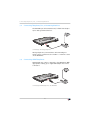
1
FRITZ!Box
Fon WLAN 7390
Installation,
Configuration
and Operation
Legal Notice
FRITZ!Box Fon WLAN 7390
This documentation and the software it describes are protected by copyright. AVM grants the nonexclusive right to use the software, which is supplied exclusively in what is known as object code
format. The licensee may create only one copy of the software, which may be used exclusively for
backup use.
AVM reserves all rights that are not expressly granted to the licensee. Without previous approval
in writing, and except for in cases permitted by law, it is particularly prohibited to
• copy, propagate or in any other manner make this documentation or this software publicly accessible, or
• process, disassemble, reverse engineer, translate, decompile or in any other manner open
the software and subsequently copy, propagate or make the software publicly accessible in
any other manner.
The licensing conditions are specified in the FRITZ!Box Fon WLAN 7390 user interface: Open the
user interface as described on page 28, click the question mark icon at the upper right, and open
the “Legal Notice”.
This documentation and software have been produced with all due care and checked for correctness in accordance with the best available technology. AVM GmbH disclaims all liability and warranties, whether express or implied, relating to the AVM product’s quality, performance or suitability for any given purpose which deviates from the performance specifications contained in the
product description. The licensee bears all risk in regard to hazards and impairments of quality
which may arise in connection with the use of this product.
AVM will not be liable for damages arising directly or indirectly from the use of the manual or the
software, nor for incidental or consequential damages, except in case of intent or gross negligence. AVM expressly disclaims all liability for the loss of or damage to hardware or software or
data as a result of direct or indirect errors or destruction and for any costs (including connection
charges) related to the documentation and the software and due to incorrect installations not performed by AVM itself.
The information in this documentation and the software are subject to change without notice for
the purpose of technical improvement.
We offer a manufacturer’s warranty for this original product. The warranty conditions are presented from page 129 of this manual.
© AVM GmbH 2011. All rights reserved. Documentation release 03/2011
AVM Audiovisuelles Marketing
und Computersysteme GmbH
Alt-Moabit 95
D 10559 Berlin
AVM Computersysteme
Vertriebs GmbH
Alt-Moabit 95
D 10559 Berlin
Germany
Germany
AVM in the Internet: www.avm.de/en
Trademarks: Unless otherwise indicated, all trademarks mentioned are legally protected trademarks owned by AVM GmbH, especially product names and logos. Microsoft, Windows and the
Windows logo are trademarks owned by Microsoft Corporation in the USA and/or other countries.
Bluetooth is a trademark of Bluetooth SIG, Inc. licensed to AVM GmbH. All other product and company names are trademarks of their respective owners.
FRITZ!Box Fon WLAN 7390
2
Table of Contents
I
CONNECTING AND OPERATION . . . . . . . . . . . . . . . . . . . . . . 8
1
Security and Handling. . . . . . . . . . . . . . . . . . . . . . . . . . . . . 8
2
FRITZ!Box Fon WLAN 7390 . . . . . . . . . . . . . . . . . . . . . . . . 10
2.1
2.2
Package Contents . . . . . . . . . . . . . . . . . . . . . . . . . . . . . . . . . . . . . . . . . 12
Operation Requirements . . . . . . . . . . . . . . . . . . . . . . . . . . . . . . . . . . . 12
3
Connecting. . . . . . . . . . . . . . . . . . . . . . . . . . . . . . . . . . . . . 14
3.1
3.2
3.3
3.4
3.5
3.6
3.7
3.8
3.9
3.10
3.11
Connecting to Electrical Power . . . . . . . . . . . . . . . . . . . . . . . . . . . . . . 14
Connecting the Computer(s) . . . . . . . . . . . . . . . . . . . . . . . . . . . . . . . . 15
Connecting Computers to the LAN Port . . . . . . . . . . . . . . . . . . . . . . . . 16
Connecting Computer(s) Wirelessly via WLAN . . . . . . . . . . . . . . . . . . 18
Connecting to the DSL Line . . . . . . . . . . . . . . . . . . . . . . . . . . . . . . . . . 21
Connecting to the Analog Telephone Line. . . . . . . . . . . . . . . . . . . . . . 22
Connecting to the ISDN Line . . . . . . . . . . . . . . . . . . . . . . . . . . . . . . . . 23
Connecting Telephone, Fax, or Answering Machine . . . . . . . . . . . . . . 24
Connecting ISDN Telephones. . . . . . . . . . . . . . . . . . . . . . . . . . . . . . . . 24
Connecting ISDN PBXs . . . . . . . . . . . . . . . . . . . . . . . . . . . . . . . . . . . . . 25
Connecting IP Telephones . . . . . . . . . . . . . . . . . . . . . . . . . . . . . . . . . . 26
4
Opening the User Interface. . . . . . . . . . . . . . . . . . . . . . . . 28
4.1
4.2
Password Protection. . . . . . . . . . . . . . . . . . . . . . . . . . . . . . . . . . . . . . . 29
Saving Your Settings. . . . . . . . . . . . . . . . . . . . . . . . . . . . . . . . . . . . . . . 30
5
Telephone Connections . . . . . . . . . . . . . . . . . . . . . . . . . . 31
5.1
5.2
5.3
5.4
Entering Your Phone Numbers . . . . . . . . . . . . . . . . . . . . . . . . . . . . . . . 31
Setting Up Telephony Devices . . . . . . . . . . . . . . . . . . . . . . . . . . . . . . . 32
Telephony Functions. . . . . . . . . . . . . . . . . . . . . . . . . . . . . . . . . . . . . . . 36
Operating the Answering Machine via Telephone Keypad. . . . . . . . . 40
3
6
Internet Connections. . . . . . . . . . . . . . . . . . . . . . . . . . . . . 41
6.1
6.2
6.3
6.4
6.5
6.6
Configuring an Internet Connection Automatically over DSL . . . . . . . 42
Configuring the Internet Connection via DSL Using the Wizard . . . . . 44
Configuring the Internet Connection via DSL Manually . . . . . . . . . . . 44
Internet Connection via Cable Modem . . . . . . . . . . . . . . . . . . . . . . . . 45
Internet Connection via the Mobile Telephone Network . . . . . . . . . . 46
Surfing the Net . . . . . . . . . . . . . . . . . . . . . . . . . . . . . . . . . . . . . . . . . . . 47
7
DECT Function . . . . . . . . . . . . . . . . . . . . . . . . . . . . . . . . . . 48
7.1
7.2
7.3
7.4
7.5
7.6
Registering the FRITZ!Fon MT-F Cordless Telephone. . . . . . . . . . . . . . 48
Registering Cordless Telephones. . . . . . . . . . . . . . . . . . . . . . . . . . . . . 49
Making an Internal Call to a Cordless Telephone . . . . . . . . . . . . . . . . 49
Searching for Cordless Telephones by Paging Call. . . . . . . . . . . . . . . 50
Logging a Cordless Telephone off of the FRITZ!Box . . . . . . . . . . . . . . 50
Enabling and Disabling DECT . . . . . . . . . . . . . . . . . . . . . . . . . . . . . . . . 50
8
USB Devices. . . . . . . . . . . . . . . . . . . . . . . . . . . . . . . . . . . . 51
8.1
8.2
8.3
8.4
8.5
8.6
8.7
8.8
Connecting USB Devices . . . . . . . . . . . . . . . . . . . . . . . . . . . . . . . . . . . 51
Accessing USB Devices . . . . . . . . . . . . . . . . . . . . . . . . . . . . . . . . . . . . 52
FRITZ!WLAN USB Stick . . . . . . . . . . . . . . . . . . . . . . . . . . . . . . . . . . . . . 52
USB Mass Storage Devices . . . . . . . . . . . . . . . . . . . . . . . . . . . . . . . . . 53
USB Printer . . . . . . . . . . . . . . . . . . . . . . . . . . . . . . . . . . . . . . . . . . . . . . 55
USB Hubs . . . . . . . . . . . . . . . . . . . . . . . . . . . . . . . . . . . . . . . . . . . . . . . 63
FRITZ!Box USB Remote Connection . . . . . . . . . . . . . . . . . . . . . . . . . . . 64
Tips for Using USB Devices . . . . . . . . . . . . . . . . . . . . . . . . . . . . . . . . . 66
9
Configuration and Operation on the Telephone . . . . . . . 68
9.1
9.2
9.3
9.4
Instructions for Operation at the Telephone. . . . . . . . . . . . . . . . . . . . 69
Audio Signals . . . . . . . . . . . . . . . . . . . . . . . . . . . . . . . . . . . . . . . . . . . . 70
Configuring on the Telephone . . . . . . . . . . . . . . . . . . . . . . . . . . . . . . . 70
Operation at the Telephone . . . . . . . . . . . . . . . . . . . . . . . . . . . . . . . . . 86
10
Troubleshooting . . . . . . . . . . . . . . . . . . . . . . . . . . . . . . . 101
10.1
10.2
10.3
10.4
Errors Opening the User Interface . . . . . . . . . . . . . . . . . . . . . . . . . . . 101
The WLAN Adapter Cannot Find FRITZ!Box . . . . . . . . . . . . . . . . . . . . 107
WLAN Connection Is Not Established . . . . . . . . . . . . . . . . . . . . . . . . 110
Obtaining an IP Address Automatically. . . . . . . . . . . . . . . . . . . . . . . 115
4
11
Removing . . . . . . . . . . . . . . . . . . . . . . . . . . . . . . . . . . . . . 120
11.1 Disconnecting the FRITZ!Box from the Computer . . . . . . . . . . . . . . . 120
11.2 Removing the Printer Port . . . . . . . . . . . . . . . . . . . . . . . . . . . . . . . . . 120
II
PRODUCT DETAILS AND USEFUL INFORMATION . . . . . . . 122
1
Product Details . . . . . . . . . . . . . . . . . . . . . . . . . . . . . . . . 122
1.1
1.2
1.3
1.4
1.5
1.6
1.7
1.8
Cable . . . . . . . . . . . . . . . . . . . . . . . . . . . . . . . . . . . . . . . . . . . . . . . . . . 122
LEDs. . . . . . . . . . . . . . . . . . . . . . . . . . . . . . . . . . . . . . . . . . . . . . . . . . . 123
WLAN Button . . . . . . . . . . . . . . . . . . . . . . . . . . . . . . . . . . . . . . . . . . . . 125
DECT Button . . . . . . . . . . . . . . . . . . . . . . . . . . . . . . . . . . . . . . . . . . . . 126
Technical Specifications . . . . . . . . . . . . . . . . . . . . . . . . . . . . . . . . . . 126
Declaration of CE Conformity . . . . . . . . . . . . . . . . . . . . . . . . . . . . . . . 128
Manufacturer’s Warranty . . . . . . . . . . . . . . . . . . . . . . . . . . . . . . . . . . 129
Disposal . . . . . . . . . . . . . . . . . . . . . . . . . . . . . . . . . . . . . . . . . . . . . . . 130
2
More about WLAN . . . . . . . . . . . . . . . . . . . . . . . . . . . . . . 131
2.1
2.2
2.3
2.4
2.5
Standards . . . . . . . . . . . . . . . . . . . . . . . . . . . . . . . . . . . . . . . . . . . . . . 131
Security . . . . . . . . . . . . . . . . . . . . . . . . . . . . . . . . . . . . . . . . . . . . . . . . 136
Frequency Ranges. . . . . . . . . . . . . . . . . . . . . . . . . . . . . . . . . . . . . . . . 139
Increasing the WLAN Range . . . . . . . . . . . . . . . . . . . . . . . . . . . . . . . . 143
WPS (Wi-Fi Protected Setup) . . . . . . . . . . . . . . . . . . . . . . . . . . . . . . . 148
3
More about Networks . . . . . . . . . . . . . . . . . . . . . . . . . . . 151
3.1
3.2
3.3
3.4
3.5
3.6
3.7
Network Overview. . . . . . . . . . . . . . . . . . . . . . . . . . . . . . . . . . . . . . . . 151
IP Settings . . . . . . . . . . . . . . . . . . . . . . . . . . . . . . . . . . . . . . . . . . . . . . 153
UPnP Settings . . . . . . . . . . . . . . . . . . . . . . . . . . . . . . . . . . . . . . . . . . . 154
IP Address . . . . . . . . . . . . . . . . . . . . . . . . . . . . . . . . . . . . . . . . . . . . . . 154
DHCP Server . . . . . . . . . . . . . . . . . . . . . . . . . . . . . . . . . . . . . . . . . . . . 155
Subnetwork. . . . . . . . . . . . . . . . . . . . . . . . . . . . . . . . . . . . . . . . . . . . . 156
Changing the Network Settings . . . . . . . . . . . . . . . . . . . . . . . . . . . . . 158
4
More about Internet Telephony . . . . . . . . . . . . . . . . . . . 159
4.1
Telephony Scenarios . . . . . . . . . . . . . . . . . . . . . . . . . . . . . . . . . . . . . 159
5
5
More about: Virtual Private Network (VPN) . . . . . . . . . . 160
5.1
5.2
5.3
5.4
What Is VPN? . . . . . . . . . . . . . . . . . . . . . . . . . . . . . . . . . . . . . . . . . . . . 160
Security through a VPN. . . . . . . . . . . . . . . . . . . . . . . . . . . . . . . . . . . . 161
Tunnel Technology . . . . . . . . . . . . . . . . . . . . . . . . . . . . . . . . . . . . . . . 162
Supplementary Software for VPN . . . . . . . . . . . . . . . . . . . . . . . . . . . 163
6
More about: Bandwidth Management and Prioritization164
6.1
6.2
Bandwidth Management . . . . . . . . . . . . . . . . . . . . . . . . . . . . . . . . . . 164
The Prioritization of Network Applications and Network Devices . . 164
7
More Functions . . . . . . . . . . . . . . . . . . . . . . . . . . . . . . . . 168
7.1
7.2
7.3
7.4
Child Protection . . . . . . . . . . . . . . . . . . . . . . . . . . . . . . . . . . . . . . . . . 168
Energy Monitor . . . . . . . . . . . . . . . . . . . . . . . . . . . . . . . . . . . . . . . . . . 168
Push Service E-mail . . . . . . . . . . . . . . . . . . . . . . . . . . . . . . . . . . . . . . 170
Night Service. . . . . . . . . . . . . . . . . . . . . . . . . . . . . . . . . . . . . . . . . . . . 170
8
Customer Service Guide . . . . . . . . . . . . . . . . . . . . . . . . . 172
8.1
8.2
8.3
8.4
Documentation . . . . . . . . . . . . . . . . . . . . . . . . . . . . . . . . . . . . . . . . . . 172
Frequently Asked Questions (FAQs) . . . . . . . . . . . . . . . . . . . . . . . . . 172
Updates and Software . . . . . . . . . . . . . . . . . . . . . . . . . . . . . . . . . . . . 173
Support from the AVM Service Team . . . . . . . . . . . . . . . . . . . . . . . . . 173
Glossary . . . . . . . . . . . . . . . . . . . . . . . . . . . . . . . . . . . . . . 175
Index . . . . . . . . . . . . . . . . . . . . . . . . . . . . . . . . . . . . . . . . 192
6
Symbols and Highlighting
Symbols and Highlighting
This symbol indicates useful hints to assist you in working with the FRITZ!Box.
This symbol indicates important instructions that must be
observed to avoid malfunctions.
The table below explains the highlighting used in this
manual:
Highlighting
Function
Examples
Quotation marks
Keys
“F1” key
Buttons
“Help”
Settings pages
“Advanced”
Menus
“Edit / Paste”
Commands
“Copy”
File paths
“C:/My Documents”
File names
“Documentation”
Underlined text
Text input
fritz.box
Pointed brackets
Joker
<Ext.>
Bold
Emphasis
Do not click the button...
7
Security and Handling
I
CONNECTING AND OPERATION
1
Security and Handling
What to Watch Out For
Safety Instructions
Handling the
FRITZ!Box
When working with the FRITZ!Box Fon WLAN 7390, observe the following security instructions in order to protect
yourself and the FRITZ!Box from harm.
•
Do not install the FRITZ!Box during an electrical
storm.
•
Disconnect FRITZ!Box from the power supply during
electrical storms.
•
Never let liquids get inside the FRITZ!Box. Otherwise,
electric shocks or short circuits may result.
•
•
The FRITZ!Box is intended for indoor use only.
Do not open the FRITZ!Box housing. The device contains hazardous components and should only be
opened by authorized repair technicians.
You can either place FRITZ!Box on a horizontal surface or
mount it on a wall. Please note the following:
•
Place or hang the FRITZ!Box in a dry location that is
free of dust and protected from direct sunlight.
For ideal operating conditions, mount the FRITZ!Box
on a wall with the cables connected on the bottom.
•
Do not place FRITZ!Box on excessively heat-sensitive
surfaces, as the base of the device can heat up during normal operation.
•
Make sure that the ventilation slits are unobstructed.
For this reason the FRITZ!Box should not be placed on
a carpet or on upholstered furniture. The ventilation
slits provide for air cooling of the FRITZ!Box.
•
When connecting FRITZ!Box to your computer using
the network, remember to take the length of the cable into account.
8
Security and Handling
•
If you would like to establish wireless connections
between FRITZ!Box and the computer, position the
device at a central location.
•
Make sure to keep sufficient distance from potential
sources of interference like microwave devices or
electric devices with large metal housings.
9
FRITZ!Box Fon WLAN 7390
2
FRITZ!Box Fon WLAN 7390
An Overview
The FRITZ!Box connects your computers directly with your DSL or VDSL
line. Each connected computer can establish an Internet connection over
the FRITZ!Box. As a WLAN access point, FRITZ!Box offers you the possibility of connecting your computer to the DSL or VDSL line wirelessly.
The FRITZ!Box is a Private Branch Exchange (PBX) for making telephone
calls via the Internet and the fixed-line network (ISDN and analog).
UMTS/HSPA modem
2.4 GHz and 5 GHz
or other DECT telephones
Notebook,
computer, PDA,
Video/TV streaming
2.4 GHz und 5 GHz
Analog telephones,
fax
ADSL/VDSL connection
with or without telephone line
ISDN telephone,
ISDN PBX
USB printer
USB storage media
Computer, games console,
network
PBX
You can connect two analog telephones, fax machines or
answering machines to the FRITZ!Box. Up to eight ISDN telephony devices can be connected to the integrated ISDN
S0 port.
Using Cordless
Telephones
Thanks to the DECT function, the FRITZ!Box can be used as
a basis station for cordless telephones. Any cordless telephone that supports the DECT-GAP standard can be registered at the FRITZ!Box.
Connecting
Computers
Four computers can be connected directly to the FRITZ!Box
using the LAN ports.
You can also connect a network hub or switch to the LAN
ports so that even more computers can be connected to
FRITZ!Box.
WLAN Access Point
The FRITZ!Box is a WLAN access point. All computers
equipped with a WLAN adapter can be wirelessly connected to the FRITZ!Box.
10
FRITZ!Box Fon WLAN 7390
Local Network
Internet
All of the computers connected with the FRITZ!Box constitute a network and can share access to any files released
for file sharing.
All of the computers connected to the FRITZ!Box can access the Internet.
The FRITZ!Box works as a DSL router, making the Internet
connection available to all connected computers. All connected computers can then use the Internet connection at
the same time.
Firewall
The FRITZ!Box is equipped with an integrated firewall. The
integrated firewall protects your network from attacks
from the Internet as long as the FRITZ!Box is operated as a
router.
USB Port
The FRITZ!Box is equipped with two ports for USB devices,
to which you can connect USB storage devices (hard drive,
stick), a printer, one of the AVM FRITZ!WLAN USB Sticks, a
USB hub or other devices (see “USB Hubs” from page 63).
The USB port supports the USB 2.0 and USB 1.1 standards.
If you use one of the FRITZ!WLAN USB Sticks by AVM, the
AVM Stick & Surf technology is at your disposal. Use
Stick & Surf to adopt the WLAN security settings from the
FRITZ!Box quickly and conveniently.
For connecting a printer, FRITZ!Box has a printer server. Alternatively, the USB remote connection is available for the
use of printers.
Media Server
Network Devices
An integrated media server makes music, image and video
files available in the local network. You can either save
these files directly in the integrated memory of the
FRITZ!Box or make them available via a USB memory stick
connected to the FRITZ!Box. A suitable playback device
linked to the local network can then play back these media contents. Any device compatible with the UPnP AV
standard can be used.
Other network devices can also be connected to the network ports of the FRITZ!Box, for instance game consoles.
11
Package Contents
2.1
Package Contents
The following is included in the FRITZ!Box Fon WLAN 7390
package:
2.2
•
•
FRITZ!Box Fon WLAN 7390
•
one network cable for connection to a computer or a
network
•
one DSL/telephone cable for connection to a DSL and
a telephone line (ISDN or analog)
•
one RJ45/RJ11 adapter (black) for connecting
FRITZ!Box Fon WLAN 7390 to the analog telephone
network
•
one RJ45/RJ11 adapter (gray) for the DSL line (required in some countries)
•
one quick guide
one power supply unit with a cable for connection to
the power mains
Operation Requirements
In order to operate the FRITZ!Box, you must have the following:
•
a Web browser that supports Java script (for instance,
Internet Explorer version 7.0 or higher, or Firefox
version 2.0 or higher)
•
an Internet connection
– a VDSL2 line, standard ITU G.993.2 Annex A or B
– or a DSL line in accordance with the standards
ITU G.992.1 Annex A or B (G.dmt), ITU G.992.3
Annex A or B (ADSL2), ITU G.992.5 Annex A or B
(ADSL2+), ITU G.994.1 (G.hs)
– or an Internet cable access with cable modem
– or a USB modem for mobile Internet access (UMTS
/HSPA)
– or another Internet connection
12
Operation Requirements
•
for connection via WLAN:
computer with a WLAN adapter compliant with
IEEE 802.11n, g, a or IEEE 802.11b, for example a
FRITZ!WLAN USB Stick
•
for connection via network cable:
computer with a network port (network adapter standard Ethernet 10/100/1000 Base-T)
•
for fixed-line telephony:
an analog telephone line or ISDN point-to-multipoint
line in accordance with the Euro ISDN protocol DSS1
13
Connecting
3
Connecting
Connecting FRITZ!Box
This chapter contains instructions on the following topics:
•
connecting FRITZ!Box to electrical power
•
•
•
•
•
•
connecting one or several computers to the FRITZ!Box
connecting FRITZ!Box to DSL
connecting FRITZ!Box to ISDN or the analog telephone line
connecting analog terminal devices to the FRITZ!Box
connecting ISDN terminal devices to the FRITZ!Box
connecting an IP telephone
Please see the instructions about setting up the
FRITZ!Box in section “Security and Handling” on page 8.
3.1
Connecting to Electrical Power
er
w
Po
SL
/D
d
xe
Fi
t
e
rn
te
In
e
n
Li
N
LA
W
FO
IN
Connecting to the power supply
Connecting
Set aside the power supply unit from the FRITZ!Box package.
1.
Connect the FRITZ!Box to the power supply unit. Insert the small plug in the power socket at the right
edge of the socket strip on the FRITZ!Box.
2.
Plug the other end into an AC power outlet.
The green “Power/DSL” LED will light up after a few seconds to indicate that the device is ready for operation.
14
Connecting the Computer(s)
3.2
Connecting the Computer(s)
If you would like to surf the web using the FRITZ!Box or to
open the FRITZ!Box user interface, then you must connect
a computer with the FRITZ!Box.
A computer can be connected with the FRITZ!Box in two
different ways:
•
•
Connection
Scenarios
via a LAN port
wirelessly via WLAN
Note the following when connecting computers to the
FRITZ!Box:
•
One computer can be connected to the FRITZ!Box by
only one of these means.
•
At each of the network ports of the FRITZ!Box, a computer can be connected directly or via a hub/switch.
•
Using WLAN you can connect multiple computers
with the FRITZ!Box at the same time.
•
The way a computer is connected to the FRITZ!Box is
the same regardless of the operating system on the
computer.
•
All of the computers connected with the FRITZ!Box
constitute a network.
15
Connecting Computers to the LAN Port
3.3
Connecting Computers to the LAN Port
If you would like to connect a computer to the LAN port of
the FRITZ!Box, make sure the computer is equipped with a
LAN port (network adapter). A LAN port is usually designated by the icon at left or labeled “LAN”.
d
xe
Fi
SL
/D
er
w
Po
t
e
rn
te
In
e
n
Li
N
LA
W
FO
IN
Connecting a computer to a LAN port on the FRITZ!Box
Connect
Set aside the network cable (yellow) from the FRITZ!Box
package.
1.
Switch on your computer.
2.
If you work with a Linux operating system, configure
your network adapter with the setting “DHCP”, if this
setting is not already configured.
3.
Insert one end of the LAN cable into the computer’s
network adapter.
4.
Connect the other end of the LAN cable to a socket on
the FRITZ!Box labeled “LAN 1”, “LAN 2”, “LAN 3” or
“LAN 4”.
Now the FRITZ!Box and computer are connected to each
other.
16
Connecting More Computers to the LAN Ports
Connecting More Computers to the LAN Ports
Additional cables are required to connect further computers. In purchasing a LAN cable, note the instructions in the
section “Network Cable” on page 123.
You can connect a computer to any of the four LAN ports of
the FRITZ!Box at any time.
Connecting a Network Hub or Switch
You can connect a network hub or switch to one of the LAN
ports on the FRITZ!Box if you would like to connect multiple computers via LAN.
er
w
Po
t
e
rn
te
In
SL
/D
e
Lin
N
LA
W
d
e
Fix
FO
IN
Connecting FRITZ!Box to a network hub
Connecting
Set aside the network cable (yellow) from the FRITZ!Box
package.
1.
Connect one end of the LAN cable to the uplink port
of the network hub or switch.
2.
Connect the other end of the cable to one of the LAN
sockets on the FRITZ!Box.
The FRITZ!Box and network hub are now connected with
each other.
17
Connecting Computer(s) Wirelessly via WLAN
3.4
Connecting Computer(s) Wirelessly via WLAN
Using WLAN you can connect one or multiple computers
with the FRITZ!Box wirelessly.
The wireless WLAN connection is independent of the operating system used. Each computer to be connected to the
FRITZ!Box via WLAN must be equipped with a compatible
WLAN adapter, for instance the FRITZ!WLAN USB Stick.
Many modern computers and notebooks have an integrated WLAN adapter.
For more information on WLAN, see the section “More
about WLAN” from page 131.
Connecting the FRITZ!WLAN USB Stick
AVM Stick & Surf
If you are using the FRITZ!WLAN USB Stick N, the
FRITZ!WLAN USB Stick N 2.4 or the FRITZ!WLAN USB Stick
by AVM as a WLAN adapter, you can establish a secure
WLAN connection quickly and conveniently using the AVM
Stick & Surf technology.
1.
Switch on your computer.
2.
Insert your FRITZ!WLAN USB Stick into one of the USB
ports on the FRITZ!Box.
The WLAN security settings are transmitted automatically to the FRITZ!WLAN USB Stick. The “Info” LED on
the FRITZ!Box begins flashing rapidly.
As soon as the “Info” LED stops flashing, transmission of the settings has been concluded.
3.
Remove the FRITZ!WLAN USB Stick from the device.
4.
Now insert the FRITZ!WLAN USB Stick into the USB
port on your computer.
The security settings saved on the FRITZ!WLAN USB Stick
are applied to the computer. Now the FRITZ!Box and
FRITZ!WLAN USB Stick are connected with each other wirelessly.
18
Establishing a WLAN Connection Using WPS
For more information, see the manual on the AVM
FRITZ!WLAN USB Stick N, the manual for the AVM
FRITZ!WLAN USB Stick N 2.4, or the manual for the AVM
FRITZ!WLAN USB Stick.
Establishing a WLAN Connection Using WPS
If you are using a WLAN adapter from another manufacturer and your WLAN adapter supports WPS (Wi-Fi Protected
Setup), you can also use this mechanism to establish the
WLAN connection between your computer and the
FRITZ!Box. For detailed instructions about how to do so,
see the section “WPS (Wi-Fi Protected Setup)” from
page 148.
Establishing a WLAN Connection Manually
Installing a WLAN
Adapter
Establishing a
Connection
If you are using a WLAN adapter from another manufacturer, you can also establish the WLAN connection manually.
To do so, proceed as follows:
1.
Switch on your computer.
2.
Install the WLAN adapter in your computer along with
the appropriate software. Please take note of the instructions in the documentation of the adapter.
3.
In order to establish a WLAN connection to the
FRITZ!Box, you can use the WLAN software for the
WLAN adapter, or the WLAN software supplied with
the operating system.
The FRITZ!Box is delivered with preset values for WLAN security. You must enter these values during the configuration of the WLAN adapter.
If you would like to establish a WLAN connection using
these preset values, then your WLAN adapter must support the WPA encryption procedure.
1.
Start the WLAN software.
2.
Enter the following values for the connection between the FRITZ!Box and the WLAN adapter:
19
Establishing a WLAN Connection Manually
SSID (name of the
FRITZ!Box Fon WLAN 7390
WLAN radio network)
3.
Encryption methods
WPA (TKIP) or WPA2 (AES-CCMP)
Encryption
WPA PSK or WPA2 PSK (AES)
WLAN key
The key is printed on the sticker on
the base of the device.
Network mode
Infrastructure
Confirm your entries using the relevant button in the
user interface (for instance, “OK” or “Connect”).
Now your WLAN adapter and the FRITZ!Box are connected
with each other wirelessly.
Please see the instructions in the section “Opening the
User Interface” on page 28. See also the information on
WLAN security in the section “Security” from page 136.
WPA Not Supported
If your WLAN adapter does not support WPA encryption,
you must convert the encryption set in the FRITZ!Box to
WEP. For this you must change the WLAN settings in the
FRITZ!Box. To do so, proceed as follows:
1.
Connect the FRITZ!Box and the computer using the
network cable (yellow) (see the section “Connecting
Computers to the LAN Port” from page 16).
2.
Start a web browser on your computer.
3.
Enter fritz.box in the address field of the browser.
4.
Select the “WLAN / Security” menu.
5.
Then select WEP encryption and enter a network key.
6.
Click the “Apply” button.
A window is displayed with the WLAN security settings.
7.
Make a note of the settings or print out the page by
clicking the printer icon in the toolbar.
8.
Close the user interface and clear the connection between the FRITZ!Box and the computer. Remove the
network cable (yellow).
20
Connecting to the DSL Line
9.
Configure your WLAN adapter with the security settings entered in the FRITZ!Box.
The WLAN connection between your WLAN adapter and
the FRITZ!Box will be established.
We strongly recommend the use of a WLAN adapter that
supports WPA or WPA2 (for instance, an AVM
FRITZ!WLAN USB Stick, see also page 18). WEP is out of
date and data encrypted with WEP can be deciphered
within minutes.
3.5
Connecting to the DSL Line
er
w
Po
SL
/D
d
xe
Fi
t
e
rn
te
In
e
n
Li
N
LA
W
FO
IN
FRITZ!Box on the DSL line: connecting to the telephone socket
Connecting
Connect the FRITZ!Box using the DSL/telephone cable
(gray/black) with the DSL line.
1.
Connect the longer, gray end of the DSL/telephone
cable to the socket on the FRITZ!Box labeled
“DSL/TEL”.
2.
Then take the short, gray end of the cable and insert
the plug (RJ45) into the socket of DSL line.
If the plug does not fit into the DSL socket, connect it
to the black RJ11/RJ45 adapter included in the package. Then insert the adapter into the DSL socket of
the DSL line.
21
Connecting to the Analog Telephone Line
As soon as the connection to the DSL line is ready for operation, the “Power/DSL” LED stops flashing and stays lit.
You can connect the FRITZ!Box to the Internet via DSL, or
using alternative access technologies. For information
about how to proceed, see the section “Internet Connections” from page 41.
3.6
Connecting to the Analog Telephone Line
Your telephone line is either an analog line or an ISDN line.
If you have an analog telephone line, then connect the
FRITZ!Box as follows:
er
w
Po
SL
/D
d
xe
Fi
t
e
rn
te
In
e
n
Li
N
LA
W
FO
IN
Connecting to the analog telephone line via the DSL splitter
Connecting
Connect the FRITZ!Box using the DSL/telephone cable
(gray/black) with the analog line.
1.
Connect the longer gray end of the cable to the socket on the FRITZ!Box labeled “DSL/TEL”.
2.
Now insert the plug of the shorter, gray end of the cable into the appropriate socket of your DSL splitter.
If the plug does not fit into the socket on the DSL
splitter, connect it to the gray RJ11/RJ45 adapter included in the package. Then insert the adapter plug
into the DSL splitter socket.
22
Connecting to the ISDN Line
Now the FRITZ!Box is connected to the telephone line.
3.7
Connecting to the ISDN Line
Your telephone line is either an analog line or an ISDN
line.
If you have an ISDN line, read here how to connect the
FRITZ!Box with the ISDN line.
d
xe
Fi
SL
/D
er
w
Po
t
e
rn
te
In
N
e
n
Li
LA
W
FO
IN
Connecting to the ISDN NT
Connecting
Set aside the Y-shaped cable (gray-black) delivered in the
package. This cable is a combined DSL/telephone cable.
1.
Connect the longer gray end of the cable to the socket on the FRITZ!Box labeled “DSL/TEL”.
2.
Insert the black branch of the Y-shaped cable into the
socket of your ISDN NT.
If the plug does not fit into the socket on the ISDN NT,
connect it to the gray RJ11/RJ45 adapter included in
the package. Then insert the adapter plug into the
ISDN NT.
Now the FRITZ!Box and the ISDN line are connected.
23
Connecting Telephone, Fax, or Answering Machine
3.8
Connecting Telephone, Fax, or Answering Machine
The FRITZ!Box provides Internet and/or fixed-line telephony for analog terminal devices.
er
w
Po
SL
/D
In
te
t
e
rn
e
n
st
Fe
tz
N
LA
W
IN
FO
Connecting to an analog telephone
Analog telephones, fax machines and answering machines can be connected to the “FON 1” or ”FON 2” socket
on the FRITZ!Box.
3.9
Connecting ISDN Telephones
ISDN telephones can be connected to the FRITZ!Box. With
appropriate cabling, up to eight ISDN telephones can be
connected.
er
w
Po
SL
/D
d
xe
Fi
t
e
rn
te
In
N
LA
e
n
Li
W
FO
IN
Connecting an ISDN telephone to the FRITZ!Box
24
Connecting ISDN PBXs
Connect
Use an ISDN cable to connect an ISDN telephone.
1.
Connect one end of the ISDN cable with the ISDN
telephone.
2.
Connect the other end of the ISDN cable with the
“FON S0” port of the FRITZ!Box.
3.10 Connecting ISDN PBXs
If you have an ISDN PBX, you can connect this PBX to
the FRITZ!Box. With the telephones connected to the
PBX you can make calls in the usual fashion.
The ISDN PBX must support a point-to-multipoint line.
er
w
Po
SL
/D
d
xe
Fi
t
e
rn
te
In
e
n
Li
N
LA
W
FO
IN
Connecting an ISDN telephone to the FRITZ!Box
Connect
Use an ISDN cable to connect an ISDN telephone.
1.
Connect one end of the ISDN cable with the ISDN
telephone.
2.
Connect the other end of the ISDN cable with the
“FON S0” port of the FRITZ!Box.
If you have no more than two analog devices connected to the PBX, you can connect them directly to
the FRITZ!Box and do without the PBX.
25
Connecting IP Telephones
3.11 Connecting IP Telephones
IP telephones can be connected to the FRITZ!Box Fon
WLAN 7390 at the LAN ports or via WLAN.
Connecting to a LAN
Port
At the LAN ports of the FRITZ!Box you can connect IP telephones using a LAN cable.
er
w
Po
t
e
rn
te
In
SL
/D
e
n
Li
N
LA
W
d
xe
Fi
FO
IN
Connecting an IP telephone to the FRITZ!Box
1.
Connect one end of the LAN cable with the IP telephone.
2.
Connect the other end of the LAN cable to one of the
LAN ports on the FRITZ!Box.
Now the IP telephone is connected to the FRITZ!Box. This
phone must be configured before you can use it for telephone calls. Follow the instructions in the documentation
of the device and in the section “Setting Up an IP Telephone in the FRITZ!Box” on page 35.
Connecting via WLAN
IP telephones that support WLAN, known as “smart
phones”, can be connected wirelessly to the FRITZ!Box via
WLAN.
er
w
Po
SL
/D
rn
te
In
et
z
et
N
LA
W
n
st
Fe
FO
IN
WLAN
Connecting a smart phone to the FRITZ!Box
26
Connecting IP Telephones
1.
Use your smart phone to search for WLAN devices at
your location.
2.
Select the FRITZ!Box Fon WLAN 7390 from the list of
WLAN devices found.
3.
To establish a connection, enter the WLAN key of the
FRITZ!Box.
The smart phone is now connected to the FRITZ!Box. Before you can make telephone calls over the FRITZ!Box using software that takes advantage of the features of an IP
telephone, this phone must be configured once. Follow
the instructions in the documentation of the device and in
the section “Setting Up an IP Telephone in the FRITZ!Box”
on page 35.
27
Opening the User Interface
4
Opening the User Interface
fritz.box
The FRITZ!Box has a user interface that can be used in a
web browser.
The user interface presents information about the
FRITZ!Box product, access and connections. This is where
you configure all of the settings for operating the
FRITZ!Box.
The user interface can be opened from any computer connected with the FRITZ!Box. The settings you configure are
saved in the FRITZ!Box.
Starting
1.
Start a web browser on your computer.
2.
Enter “fritz.box” in the address field of the browser.
The “fritz.box” address entry in the address field of an Internet
browser
The FRITZ!Box user interface opens.
If the user interface does not open, please see the instructions in the section “Errors Opening the User Interface” from page 101.
28
Password Protection
4.1
Password Protection
You can protect the FRITZ!Box user interface from unauthorized and unwelcome access by setting up a password.
Only users who know the password can access the user interface. This protects all settings and all information in the
FRITZ!Box.
We strongly recommend setting up and using password
protection for the user interface.
Please note the following once you have enabled password protection:
•
When the user interface is opened, the login screen
will be displayed first. Enter the password here to log
in to the user interface.
•
If you do not click on the user interface for a period of
longer than ten minutes, you will be logged off the
user interface automatically.
The next time you click on the user interface you
must log back in.
•
There are some pages in the user interface from
which the user is not logged off automatically. These
are pages that show constantly changing information, which are refreshed automatically at regular
intervals. The “Overview” page is one example.
•
You can log yourself off the user interface by clicking
the icon with the padlock at the top right.
•
Be sure to use a password you can remember easily.
If you forget the password, the only way to access the
FRITZ!Box is to restore the factory settings. All settings made during operation will be overwritten. Then
you can open the user interface again in order to reconfigure your settings or restore the settings you
saved during previous operation.
29
Setting Up Password Protection
Setting Up Password Protection
There are several ways to set up password protection in
the FRITZ!Box:
•
On the login screen:
As long as password protection is not enabled and
you have not switched off the prompt to use password protection, you will be prompted to set up password protection every time you open the user interface.
•
In the “System / FRITZ!Box Password” menu:
In this menu you can set up password protection, or
change a password that has already been set up.
4.2
Saving Your Settings
The settings you made in the FRITZ!Box can be saved as a
file on your computer. This file contains all user-defined
settings, including the account information for the Internet and telephony connections. This settings file can be
loaded back to your FRITZ!Box at any time.
The FRITZ!Box features a Wizard to accompany you step by
step through the process of saving and restoring your settings.
30
Telephone Connections
5
Telephone Connections
Configuring FRITZ!Box for Telephony
Using the FRITZ!Box you can make telephone calls via the Internet and
the fixed-line network.
Once you have connected the FRITZ!Box as described in the chapter
“Connecting” from page 14, you can configure the FRITZ!Box for making
telephone calls.
The configuration is performed in two consecutive steps:
•
•
entering your phone numbers
configuring the connected telephony devices
In the FRITZ!Box user interface there are various Wizards
for the configuration of your FRITZ!Box. We recommend
using these step-by-step instructions.
5.1
Entering Your Phone Numbers
The “Managing Your Own Phone Numbers” Wizard supports you in performing the following tasks:
•
•
•
•
entering Internet telephone numbers
entering fixed-line numbers
changing numbers already entered
deleting entered numbers
If you used the Basic Configuration Wizard after connecting your FRITZ!Box and entered numbers then, these numbers are already entered in your FRITZ!Box. In this case
you can start right away with the configuration of the connected telephony devices.
31
Entering New Internet Telephone Numbers
Entering New Internet Telephone Numbers
In order to be able to make calls via the Internet with the
FRITZ!Box, you will need an Internet telephone number
from an Internet telephony provider. Enter the Internet
telephone number in the FRITZ!Box.
You can enter multiple Internet numbers in the FRITZ!Box.
The Internet numbers can be from one or from multiple different Internet telephony providers.
Entering Fixed-line Numbers
With the FRITZ!Box you can make calls both via the analog
fixed-line network and via the ISDN fixed-line network:
5.2
•
In order to make calls via the analog fixed-line network, enter your telephone numbers in the FRITZ!Box.
•
In order to make calls via the ISDN fixed-line network,
enter your ISDN numbers in the FRITZ!Box.
Setting Up Telephony Devices
For the configuration of telephony devices, the “Manage
Your Telephony Devices” Wizard is available in the
FRITZ!Box.
Telephony Devices Supported
The following telephony devices are supported by the
FRITZ!Box:
•
telephones
– analog telephones
– ISDN telephones
– telephones with an integrated answering machine
– cordless (DECT) telephones
– IP telephones
32
Settings for Telephony Devices
•
answering machine
If you have connected an analog answering machine
(to the “FON 1” or “FON 2” socket, for instance), configure it as an answering machine.
The FRITZ!Box is also equipped with integrated answering machines, which can be enabled and configured in the “Telephony / Telephony Devices” menu.
•
ISDN Telephone Systems (PBXs)
– ISDN PBXs for analog telephones
– ISDN PBXs for ISDN telephones
•
fax machines
The FRITZ!Box is equipped with an integrated fax machine for receiving faxes. This integrated device can
be enabled and configured in the “Telephony / Telephony Devices” menu.
The FRITZ!Box also supports:
– analog fax machines
– analog fax-telephone combinations
Settings for Telephony Devices
Telephony devices like telephones, faxes and answering
machines can be connected to the FRITZ!Box. The
FRITZ!Box is also equipped with integrated answering machines and a fax machine for fax reception.
The “Managing Your Telephony Devices” Wizard can assist
you in configuring the necessary settings for all telephony
devices:
Devices Connected to
the FRITZ!Box
•
telephone
– kind of connection used to connect the telephone
with the FRITZ!Box
– internal name for the telephone
33
Settings for Telephony Devices
– Number used to conduct outgoing calls: With this
entry you specify whether outgoing calls should
be conducted via the Internet or the fixed-line network.
– Call acceptance: Specify here whether the telephone should react to all calls or only to calls for
certain telephone numbers.
•
fax machine
– kind of connection used to connect the fax machine with the FRITZ!Box
– internal name for the fax machine
– Number used to send faxes: This entry defines
whether outgoing faxes are sent via the Internet
or the fixed-line network.
– Call acceptance: Here you define the numbers to
which the fax machine should react.
•
answering machine
– kind of connection used to connect the answering
machine with the FRITZ!Box
– internal name for the answering machine
– Call acceptance: Enter here whether the answering machine should react to all calls or only to
calls for certain numbers.
•
ISDN PBX
The Wizard explains step by step how to prepare the
ISDN telephone system for operation at the FRITZ!Box
and what settings you can configure.
Devices Integrated in
the FRITZ!Box
•
fax reception
– fax ID to be transmitted to the sender of the fax
– e-mail address to which the incoming faxes are
forwarded
34
Setting Up an IP Telephone in the FRITZ!Box
– USB memory on which the incoming faxes are
stored. For this option a USB memory device must
be connected to the USB port of the FRITZ!Box.
– Automatic fax detection for an analog fixed line,
which detects whether an incoming call is a fax.
•
Answering machine
– specifications about how calls should be accepted, and whether the message should also be sent
by e-mail
– internal name for the answering machine
– Call acceptance: Enter here whether the answering machine should react to all calls or only to
calls for certain numbers.
– Remote inquiry, which can be used to pick up
messages from the answering machine from another telephone line.
Setting Up an IP Telephone in the FRITZ!Box
Before you can use an IP telephone with the FRITZ!Box, it
must be set up. Follow the instructions below:
See also the manufacturer’s documentation for information about how to set up your IP telephone.
1.
Open the FRITZ!Box user interface (see the section
“Opening the User Interface” on page 28).
2.
Enable the “Expert Mode” settings in the “System”
menu.
3.
Click “Wizards /Managing Your Telephony Devices”
and then click “Next”.
4.
Select the option “Telephone” and then click “Next”.
5.
Select “LAN/WLAN (IP telephone)”, assign a name
and then click “Next”.
6.
Assign a password.
35
Telephony Functions
7.
Enter the password, the user name and the registrar
in your IP telephone. Be sure to consult the documentation for your telephone on how to do this.
8.
Confirm the Telephony Wizard of the FRITZ!Box by
clicking “Next” and follow the instructions.
The IP telephone will be set up in the FRITZ!Box so that it
can be used to make telephone calls.
5.3
Telephony Functions
More functions and settings options for telephony are
available in the “Telephony” menu.
Call List
The “Call List” displays outgoing calls and sent faxes, incoming calls and faxes, as well as incoming calls during
absence.
If the number of a caller or someone called is entered in
the telephone book, the “Call List” will display the name
from the telephone book.
The “Call List” can be saved as a file.
Menu
The “Call List” is found in the “Telephony / Calls” menu.
Telephone Book
A telephone book is at your disposal in the FRITZ!Box.
Menu
The “Telephone Book” is found in the “Telephony” menu.
36
Call Diversion
Call Diversion
With this function you can divert incoming calls to another
number. The following kinds of call diversion are available:
Menu
•
diversion of all incoming calls to a certain telephone
number
•
•
diversion of calls for certain numbers
•
diversion of calls to other that come from a certain
telephone number
diversion of calls to other telephones connected with
the FRITZ!Box
The “Call Diversion” menu is located in the “Telephony”
menu.
Block Calls
The telephone number block of the FRITZ!Box offers you
the following options:
•
numbers and number ranges can be blocked for outgoing calls
From the FRITZ!Box no outgoing calls to a blocked
number range are possible. In this manner you can
block connections to certain mobile networks, for instance.
•
blocking telephone numbers for incoming calls
For incoming calls you can block certain numbers to
avoid receiving calls from unwanted callers.
Menu
The command for blocking calls is located in the “Telephony / Calls” menu.
37
Alarm
Alarm
With the alarm function you can use the telephones connected to the FRITZ!Box as alarm clocks.
Menu
•
You can specify several different times for the alarm
to go off.
•
An individual telephone can be selected for the alarm
function.
The “Alarm” function is located in the “Telephony” menu.
Dialing Rules
Dialing rules specify when calls are conducted on the
fixed-line network, and when they take place over the Internet.
All connections to number ranges for which a dialing rule
has been defined are established using the specified connection type.
Menu
The “Dialing Rules” menu is located in the “Telephony”
menu.
Integrated Fax
The FRITZ!Box is equipped with an integrated fax function
so that you can receive faxes without having to connect a
fax machine. The integrated fax machine forwards incoming faxes to an e-mail address, or stores them on a USB
memory device connected to the FRITZ!Box.
For operation the integrated fax machine must be set up
using the Wizard for telephony devices in the FRITZ!Box
user interface. Enter an e-mail address to which incoming
faxes should be forwarded.
If the FRITZ!Box is connected to an analog fixed line with
only one number, remember to enable automatic fax detection as well. The fax detection works passively, meaning that it does not detect an incoming fax until a call has
been accepted. For this reason we recommend also using
38
Integrated Answering Machine
the wizard for telephony devices to set up an answering
machine, so that fax detection can also function when you
do not accept a call.
The integrated fax machine of the FRITZ!Box supports only
fax reception. To send faxes you can install the “FRITZ!fax
for FRITZ!Box” software. This program can be downloaded
from the AVM web site for the operating systems
Windows 7, Windows Vista and Windows XP.
Integrated Answering Machine
The FRITZ!Box is equipped with several integrated answering machines, each of which can be enabled and configured individually.
By enabling the setting “Send messages by e-mail” you
can have recorded messages sent to you by e-mail. The
messages are sent as audio files.
To check an answering machine internally, enter the following keypad sequences:
Answering machine 1
ss600
Answering machine 2
ss601
Answering machine 3
ss602
Answering machine 4
ss603
etc.
etc.
An overview of the answering machine menu is presented
in the section “Operating the Answering Machine via Telephone Keypad” on page 40.
Menu
The integrated answering machines can be enabled and
configured in the “Telephony / Telephony Devices” menu.
39
Operating the Answering Machine via Telephone Keypad
5.4
Operating the Answering Machine via Telephone Keypad
Main menu
1
Play back messages
If no messages have been recorded, you hear two short audio signals and return to the main menu.
1
Play back messages
3
Call back the caller of the message
5
Delete message
7
To previous message
9
To next message
0
Listen to “Play back messages” menu again
r
Back to main menu
2
Delete all messages
3
Switch the answering machine on / off
4
Record greetings
1
Record greeting message
2
Record announcement
3
Record closing announcement
Record and select
1
Listen to all greetings/announcements of the selected type > Select the desired recording by pressing 2
5
Delete greeting/announcement
8
Record greeting/announcement > End recording by pressing 1
0
Listen to “Record and Select” menu again
r
Back to main menu
0
Listen to “Record greetings” menu again
r
Back to main menu
5
Switch recording and directions mode on / off
0
Listen to main menu again
40
Internet Connections
6
Internet Connections
Setting Up the Internet Connection
In order to allow Internet access with the FRITZ!Box, you must first configure the Internet connection in the FRITZ!Box user interface.
The FRITZ!Box can be operated directly at the DSL line. Alternatively, it
can be connected to a cable modem, a DSL modem, or a DSL router, or
integrated into an existing network.
If no DSL line is available, Internet connections can also be established
over the mobile telephone network using a USB modem.
There are various ways to set up the Internet connection of
your FRITZ!Box. In addition to the manual configuration
variations, your Internet Service Provider may also offer
automatic configuration of the Internet connection.
This chapter describes the various ways you can use the
FRITZ!Box technology to set up an Internet connection.
Nevertheless it is always advisable to follow the configuration instructions you received from your Internet Service
Provider.
Also note the following for the setup of your FRITZ!Box’s
Internet connection:
•
The Internet connection of the FRITZ!Box can be established using only one of the methods described
below.
•
Your Internet Service Provider transmitted you information about the configuration of your Internet connection. Always perform the Internet connection setup as described by your provider!
•
If your Internet Service Provider supports an automatic setup routine (also known as “automatic configuration”, “autoconfiguration”, “remote configuration”
41
Configuring an Internet Connection Automatically over DSL
or “autoprovisioning”), we recommend always setting up the Internet connection of your FRITZ!Box in
this way.
The FRITZ!Box then is set up automatically and securely, with the data necessary for Internet use and
any other services ordered from your provider, like Internet telephony.
•
If you would like to use not only DSL, but also
UMTS/HSPA for Internet connections, note that the
Internet connection can be used by only one of these
access technologies. You will have to change the type
of access in the FRITZ!Box as needed.
Remember that you can configure in the FRITZ!Box
only those types of Internet access you have contracted with the appropriate providers.
6.1
Configuring an Internet Connection Automatically over DSL
Automatic configuration is a procedure in which the Internet Service Provider sets up the Internet connection of
your FRITZ!Box completely automatically by “Plug & Play”.
Prerequisites
In order for you to be able to perform automatic configuration, the following requirements must be met:
•
Your FRITZ!Box is brand new and starting operation
for the first time
or
The factory settings were restored to your existing
FRITZ!Box (see page 71) and the Internet connection
has to be set up again.
•
The provider you contracted your Internet connection
from supports automatic configuration.
Follow all of the information you received from your provider on configuring your Internet connection!
If these prerequisites are not fulfilled, you can set up your
FRITZ!Box using the Configuration Wizard (see page 44).
42
Configuring an Internet Connection Automatically over DSL
The Automatic
Configuration
Procedure
Proceed as follows to perform automatic configuration:
Your Internet Service Provider transmitted you information about the configuration of your Internet connection.
Always perform the Internet connection setup as described by your provider!
1.
Connect the FRITZ!Box to the DSL line.
The automatic configuration starts automatically.
2.
Wait until the automatic configuration has concluded. This process can take around five to ten minutes.
During this time the FRITZ!Box receives all necessary
settings directly from the autoconfiguration server of
your Internet Service Provider.
After automatic configuration you can surf the web
and use any other contracted services (like Internet
telephony) right away.
3.
To check that the automatic configuration was completed successfully, open a web browser and enter
any Internet address.
Then you may want to try out the other services ordered from your Internet Service Provider, such as Internet telephony.
Further settings can be configured in the user interface of
your FRITZ!Box. The “Wizards” area offers easy-to-use,
step-by-step instructions on all important functions. Use
these to set up the FRITZ!Box in accordance with your own
needs.
43
Configuring the Internet Connection via DSL Using the Wizard
6.2
Configuring the Internet Connection via DSL Using the Wizard
If the FRITZ!Box is connected directly to the DSL line, the
account information from your Internet Service Provider is
required to configure the Internet connection in the
FRITZ!Box.
Use the Wizard to configure the Internet connection:
6.3
1.
Open the FRITZ!Box user interface.
2.
Select the “Wizards” menu.
3.
Click the “Check Internet Connection” Wizard and follow the instructions.
Configuring the Internet Connection via DSL Manually
Changes to the Internet connection settings can be made
in the FRITZ!Box user interface.
Proceed as follows:
1.
Open the FRITZ!Box user interface.
2.
Select “Internet / Account Information”.
3.
Configure the desired settings. Take advantage of the
Help available in the FRITZ!Box user interface for
more information and instructions.
4.
As a final step, click “Apply”.
If the FRITZ!Box is connected to a DSL modem or a DSL
router, or integrated into an existing network, you must also configure your Internet connection as described above.
To do so, enable the expert settings in the “System / Expert Mode” menu.
44
Internet Connection via Cable Modem
6.4
Internet Connection via Cable Modem
With an additional cable modem you can also use your
FRITZ!Box Fon WLAN 7390 on a cable connection. Then the
Internet connection is established and controlled by the
FRITZ!Box itself, so that in this operating mode, too, all
FRITZ!Box functions (like Internet telephony, firewall) are
available without restriction.
1.
Use a network cable to connect the cable modem
with the “LAN 1” port on the FRITZ!Box.
2.
Connect a computer with the FRITZ!Box either wirelessly via WLAN or using a network cable.
3.
Open the FRITZ!Box user interface.
4.
Enable the expert settings of the FRITZ!Box in the
“System / Expert Mode” menu. Confirm by clicking
“Apply”.
5.
Open the “Internet / Account Information / Settings”
menu.
6.
Select the connection type “Internet connection via
LAN 1” from the “Connection via” area.
7.
In the “Operating Mode” section, enable the option
“Establish own Internet connection (NAT router with
PPPoE or IP)”.
8.
In the “Account Information” section, select the option “No account information required (IP)”.
9.
In the “Connection Settings” section, enable the option “Obtain the IP address automatically (DHCP)”.
10. In the input fields “Upstream” and “Downstream”,
enter the relevant speeds of your Internet connection.
11. Save your settings by clicking “Apply”.
12. Then restart the cable modem, for instance, by unplugging it briefly from the electrical outlet.
Now the Internet connection of the FRITZ!Box will be established over the cable modem.
45
Internet Connection via the Mobile Telephone Network
6.5
Internet Connection via the Mobile Telephone Network
In situations where DSL is not available, you can use your
FRITZ!Box Fon WLAN 7390 to connect to the Internet via
the mobile telephone network. A USB modem for mobile
Internet access (UMTS/HSPA) is required for this.
The USB modem is simply inserted into the USB port of
the FRITZ!Box.
The FRITZ!Box supports UMTS/HSPA modems from various
manufacturers.
When the mobile telephone network function is used, the
FRITZ!Box user interface presents information about network availability, connection status and transmission rate.
1.
Insert the USB modem into the USB port on the
FRITZ!Box.
2.
Open the FRITZ!Box user interface.
3.
Click the “Home Network / USB Devices” menu. On
the “Overview of Devices” tab, the USB modem is
displayed as a “Mobile telephone network modem”.
4.
Click “Enable mobile telephone network modem
now”.
The “Mobile Telephone Network” menu opens to let
you set up the USB modem.
The “Mobile Telephone Network” menu is not available until the USB modem has been connected to
the FRITZ!Box. From this point on the menu is always
available, even when the USB modem has been disconnected.
5.
Configure the settings for your Internet connection
over the mobile telephone network. For more information, see the Online Help of the FRITZ!Box.
46
Surfing the Net
Due to technical limitations on the part of the mobile telephone network carriers, some limitations may arise for Internet telephone calls and for applications requiring an incoming connection. The same is true for using port forwarding, sharing USB storage memory, remote maintenance via
HTTPS, dynamic DNS and VPN. Contact your network carrier
for details on any restrictions that may apply.
6.6
Surfing the Net
Once you have set up the Internet connection in your
FRITZ!Box, you can surf the Internet with any computer
connected to the FRITZ!Box.
1.
Start a web browser on your computer.
2.
Enter in the address field the URL of the web page
you would like to visit, for instance
http://www.avm.de/en.
47
DECT Function
7
DECT Function
Cordless Telephony with FRITZ!Box
Thanks to the integrated DECT function, the FRITZ!Box Fon WLAN 7390
can be used as a base station for cordless telephones that support the
DECT GAP or CAT-iq standard. A total of up to five cordless telephones
can be registered on the FRITZ!Box.
7.1
Registering the FRITZ!Fon MT-F Cordless Telephone
The AVM FRITZ!Fon MT-F supports the DECT radio standard, making it an ideal handset for your FRITZ!Box Fon
WLAN 7390.
Proceed as follows to register FRITZ!Fon MT-F at the
FRITZ!Box:
1.
Switch FRITZ!Fon MT-F on by pressing and holding
down the hang-up button.
2.
Press the DECT button on your FRITZ!Box until
FRITZ!Fon MT-F indicates that registration has been
successful.
The FRITZ!Fon MT-F is now connected with your FRITZ!Box
and can be used to make telephone calls.
If registration is not successful, see the instructions for
manual registration in the manual of your FRITZ!Fon MT-F.
FRITZ!Fon MT-F Scope of Service
FRITZ!Fon MT-F is optimized for connections with your
FRITZ!Box to provide not only telephone connections, but
a whole range of additional features.
•
With FRITZ!Fon MT-F you can read the e-mail sent to
your e-mail account with an e-mail provider. For this
the POP3 protocol is used to retrieve your e-mail from
your mailbox at the e-mail provider so that it can be
displayed on the handset.
•
You can set up multiple e-mail accounts on your
FRITZ!Box, and, if you have more than one
FRITZ!Fon MT-F, assign the display of each account to a
certain FRITZ!Fon MT-F.
48
Registering Cordless Telephones
•
With FRITZ!Fon MT-F you can use your FRITZ!Box telephone book. New numbers recorded in a call list on
FRITZ!Fon MT-F can be transferred directly from the
call list to the FRITZ!Box telephone book.
For detailed descriptions of this and other features, see
the documentation for your FRITZ!Fon MT-F.
7.2
Registering Cordless Telephones
With FRITZ!Box Fon WLAN 7390 you can use all cordless
telephones that support the DECT-GAP and CAT-iq radio
standards. See the documentation of your cordless telephone to find out whether it supports either of these standards.
To register a cordless telephone from any manufacturer on
the FRITZ!Box, please follow the corresponding instructions in your telephone manual.
Press and hold down the search key on the FRITZ!Box labeled “DECT” during the entire registration process. This
facilitates telephone registration.
7.3
Making an Internal Call to a Cordless Telephone
All telephones connected to the FRITZ!Box can establish
connections to each other free of charge.
Telephones from other manufacturers can establish internal connections using internal numbers, which are assigned to each telephone automatically upon registration.
The internal numbers of the telephones you have connected are listed in the FRITZ!Box user interface. Perform the
following steps:
1.
Start a web browser.
2.
Open the FRITZ!Box user interface by entering
fritz.box.
3.
On the “Overview” page, select the “Telephone
Book” entry.
4.
Select the “Internal Numbers” tab.
49
Searching for Cordless Telephones by Paging Call
The internal numbers of the telephones connected to the
FRITZ!Box are displayed.
7.4
Searching for Cordless Telephones by Paging Call
Using the DECT button on the top of the device you can
search for lost handsets by starting a paging call.
Press the DECT button briefly and all of the cordless telephones connected with the FRITZ!Box will ring. A paging
call cannot work if a handset has dead batteries.
The DECT button and its use are described in the section
“DECT Button” on page 126.
7.5
Logging a Cordless Telephone off of the FRITZ!Box
1.
Start a web browser.
2.
Open the FRITZ!Box user interface by entering
fritz.box.
3.
On the “Overview” page, click the on “DECT” entry in
the “Interfaces ” area.
4.
Select the cordless telephone you want to log off and
click the “Delete” button.
Now the cordless telephone will be logged off.
7.6
Enabling and Disabling DECT
The DECT function is disabled upon delivery of the
FRITZ!Box.
•
Enabling the DECT function
The DECT function is switched on when the first cordless telephone is registered.
•
Disabling the DECT function
When the last cordless telephone is logged off in the
FRITZ!Box user interface, the DECT function is
switched off automatically.
50
USB Devices
8
USB Devices
USB Devices at the FRITZ!Box
The FRITZ!Box Fon WLAN 7390 is equipped with two USB ports (also
known as USB host controllers).
The USB ports of the FRITZ!Box support the standards USB 2.0 and
USB 1.1.
Various USB devices can be connected to the USB ports:
•
a FRITZ!WLAN USB Stick N 2.4, a FRITZ!WLAN USB Stick N or an
AVM FRITZ!WLAN USB Stick
•
•
•
•
a USB storage device (hard drive, memory stick, card reader)
a USB printer
a USB modem (UMTS/HSPA)
USB hubs
If you use USB hubs, note that a maximum of four USB devices can
be operated on the FRITZ!Box.
8.1
Connecting USB Devices
DSL/TEL
FON 1 FON
2
LAN 1
LAN 2
Connecting a USB cable to the USB port
Connecting
Some USB devices, such as memory sticks or the
FRITZ!WLAN USB Stick N, are inserted directly into one of
the USB ports on the FRITZ!Box. Other devices like USB
printers are connected to one of the USB ports by means
of a USB cable.
51
Accessing USB Devices
If you would like to use multiple devices at one USB port,
you can also use a USB hub (see the section “USB Hubs”
on page 63). Please read the “Tips for Using USB Devices”
on page 66 first.
8.2
Accessing USB Devices
Network Sharing
USB Remote
Connection
As soon as a USB device is connected to the FRITZ!Box, all
of its functions are available in the entire network:
•
The files in the USB mass storage can be accessed
from the network via FTP (File Transfer Protocol), or
you can make the USB mass storage device available
as a network storage device. The two kinds of access
are explained in greater detail in the section “Accessing the Data on the USB Mass Storage” on page 54.
•
USB printers are available as network printers.
With the USB remote connection, a computer in the network can use USB devices just as if they were connected
directly to the computer via the USB cable (virtual cable
replacement). This can make sense for multifunctional
printers, for instance, so that you can use the integrated
card reader/scanner or the ink level display.
While a computer accesses a USB device via the USB remote connection, the USB device is not available for other
computers in the network.
For more information on the USB remote connection, see
the section “FRITZ!Box USB Remote Connection” from
page 64.
8.3
FRITZ!WLAN USB Stick
The FRITZ!WLAN USB Stick N, the FRITZ!WLAN USB
Stick N 2.4 and the FRITZ!WLAN USB Stick are WLAN
adapters manufactured by AVM for connection to a computer. Using a WLAN adapter you can connect the computer wirelessly with the FRITZ!Box.
All FRITZ!WLAN USB Sticks from AVM master the
Stick & Surf method, making it easy to establish a secure
WLAN connection: The FRITZ!WLAN USB Stick is inserted
52
USB Mass Storage Devices
briefly into one of the USB ports on the FRITZ!Box, where it
receives all of the security settings required for the WLAN
connection to this FRITZ!Box.
For instructions on establishing a WLAN connection using
Stick & Surf, see the section “Connecting the
FRITZ!WLAN USB Stick” from page 18. For more information on the various FRITZ!WLAN USB Sticks by AVM and
the WLAN standards each of them supports, see the
FRITZ!WLAN USB Stick N manual, the FRITZ!WLAN USB
Stick N 2.4 manual, or the manual for the FRITZ!WLAN USB
Stick.
8.4
USB Mass Storage Devices
USB storage devices include hard drives, memory sticks,
and card readers.
File Systems
Access to USB memory devices connected to the
FRITZ!Box is possible via the File Transfer Protocol (FTP),
network storage and USB remote connection functions.
USB storage devices using the file systems FAT, FAT32 and
NTFS are supported. Files in the FAT and FAT32 file systems are supported up to a size of 4 GB. This limit does
not apply in the NTFS file system, where even larger files
can be accessed.
Access Rights and Password Protection
You can define access rights and password protection for
the USB storage devices. These settings are valid for all
USB storage devices connected to the FRITZ!Box. It is not
possible to assign specific read or write access or an individual password to each storage device.
Configuring
Proceed as follows to define access rights and password
protection for the USB storage devices:
1.
Start a web browser.
2.
Enter fritz.box in the address field.
3.
Select the “Home Network / Storage (NAS)” menu.
4.
Select the “Security” tab.
53
Accessing the Data on the USB Mass Storage
5.
Configure the access rights and password protection
for the USB mass storage devices.
The access rights and password are are not enabled if the
USB remote connection is enabled for all USB storage devices.
Accessing the Data on the USB Mass Storage
USB storage devices connected to the FRITZ!Box directly
or via a USB hub are displayed with their device name in
the “Home Network / USB Devices” menu on the user
interface.
FRITZ!NAS
All of the computers in the network can access the data in
the USB mass storage simultaneously via FTP.
Click the “Start FRITZ!NAS” button in the “Home Network /
Storage (NAS) / FRITZ!NAS” menu. The folder structure of
the storage available via FRITZ!NAS is displayed in yor web
browser.
Now you can select the desired USB storage device and
double click to view the data stored there. As soon as you
set a checkmark in front of a file name, you can click any
of the buttons at the top of the list to apply the associated
function.
Files on the USB storage device cannot be run or opened
until they have been copied to your computer or to your local network.
Media Server
With this option music, image and video files on the USB
storage device can be played back by compatible devices
(streaming). The USB storage device with the media collection is simply connected to the USB port on the
FRITZ!Box and a suitable playback device is linked to the
local network.
The devices automatically communicate via Universal Plug
& Play (UPnP). This technology allows the devices connected to each other by cable or radio network to perform
automatic detection, recognize events, and exchange data
with each other accordingly. With UPnP AV this technology
has been expanded to audio and video contents.
54
USB Printer
With the media server, media files of all kinds of formats
can be made available from the connected USB storage
device via UPnP.
The USB network storage, media server and FTP functions
can be used only if the USB remote connection is not enabled for USB storage devices.
8.5
USB Printer
To connect a USB printer to one of the USB ports of the
FRITZ!Box, you can either enable the USB remote connection or use the USB printer as a network printer.
USB Printer at the USB Remote Connection
If you enable the USB remote connection for USB printers,
then you can use the printer on another computer just as if
it were connected directly to your computer (virtual cable
replacement).
•
If you want to use the printer with the USB remote
connection enabled, then the program for the USB remote connection (see page 64) and the suitable
printer drivers must be installed on any computer
that is supposed to use the printer.
•
When the USB remote connection is enabled, all-inone printers (printers with supplementary fax or
scanner functions) can also be used for faxing and
scanning.
•
If your printer is equipped with a status monitor, you
can use this feature when the USB remote connection
is enabled.
•
Host-based printers, like those that expect printer
status message responses from the system (bidirectional communication as in the GDI system, for instance), can only be used via the USB remote connection. These printers usually can be used only with
an operating system for which the printer manufac-
55
USB Printer as a Network Printer
turer has provided driver software. Such printers connected to the FRITZ!Box are not supported as network
printers.
USB Printer as a Network Printer
When you connect a USB printer to the FRITZ!Box and set it
up without using the “USB Remote Connection” software,
the FRITZ!Box manages the printer itself and makes it
available as a network printer to all computers connected
to the FRITZ!Box. Please note the following for the printer
setup:
•
If you want to use the printer as a network printer, the
printer connection must be configured, and the suitable printer drivers installed, on every computer.
Print jobs are forwarded to the IP address of the
printer server in the local network via the printer port.
•
Only printers that can be addressed with the device
class “Printer” are supported as network printers.
This is generally not the case for multi-function devices, for instance combined fax-scanner-printers.
•
If your printer is equipped with a status monitor, it
may not be possible to use the status monitor if the
printer is operated as a network printer.
•
For multi-function devices (printers with additional
functions like fax or scanning), only the printing function is supported for network printers.
56
USB Printer as a Network Printer
Configuring the Windows Printer Port for a Network
Printer
If the “FRITZ!Box” entry is already listed in the “Programs”
group of the start menu of the computer, this means that
the printer port is already configured on this computer.
Otherwise, work through the instructions below to configure the printer port.
Note that this manual describes only how to configure
and install the printer port in the 32-bit versions of the
Windows operating systems.
If you use a 64-bit Windows operating system on your
computer, please proceed according to the corresponding
instructions on the AVM web site.
Complete the steps below to set up the printer port in a
32-bit Windows operating system:
1.
Insert the FRITZ!Box CD in the computer’s CD_ROM
drive.
The Installation Help opens.
2.
Click the “View CD Contents” button.
3.
Click the “Create Start Menu Entry” button.
The printer port designated “AVM: (FRITZ!Box USB
Printer Port)” will be configured.
Now you can install the printer drivers of the printer connected to FRITZ!Box for this printer port.
Installing Printer Drivers in Windows 7
1.
Click the “Start” button in the task bar and select
“Devices and Printers”.
2.
Click “Add a printer”.
3.
Select “Add a local printer”.
You must make this selection because the printer
port on the computer functions as a local port.
57
USB Printer as a Network Printer
4.
Select the “Use an existing port:” setting and then
choose the entry “AVM: (FRITZ!Box USB Printer Port)”
from the list. Click “Next”.
5.
Select the manufacturer for the USB printer connected to the FRITZ!Box from the “Manufacturers” list and
then select the exact model from the “Printers” list.
Click “Next”.
If the manufacturer or the model is not included in
the lists, use an installation disk or CD with the required files and click “Have Disk...”.
6.
You can enter a name for the printer in the “Printer
name” field. The operating system will use this name
to administer the printer.
7.
Click “Next”. Installation will be concluded.
Installing Printer Drivers in Windows Vista
1.
Click the “Start” button in the task bar and select the
“Control Panel”.
2.
Select “Printers”.
3.
Click “Add Printer”.
4.
Select “Add a local printer”.
You must make this selection because the printer
port on the computer functions as a local port.
5.
Select the “Use an existing port” setting and then
choose the entry “AVM: (FRITZ!Box USB Printer Port)”
from the list. Click “Next”.
6.
Select the manufacturer for the USB printer connected to the FRITZ!Box from the “Manufacturers” list and
then select the exact model from the “Printers” list.
If the manufacturer or the model is not included in
the lists, use an installation disk or CD with the required files and click “Have Disk...”.
7.
You can enter a name for the printer in the “Printer
Name” field. The operating system will use this name
to administer the printer.
58
USB Printer as a Network Printer
8.
Conclude the installation by clicking “Finish”.
Installing Printer Drivers in Windows XP/2000
1.
Open the start menu of the computer and click the
“Printers and Faxes” entry (Windows XP) or click
“Start / Settings / Printer” (Windows 2000).
2.
In the “Printers and Faxes” window, click “Add a
printer”.
The “Add Printer” Wizard will be started.
3.
Click “Next”.
4.
Select the option “Local printer attached to this computer” (Windows XP) or “Local Printer”
(Windows 2000) and make sure that the setting “Automatically detect and install my Plug and Play printer” is disabled.
You must make this selection because the printer
port on the computer functions as a local port.
5.
Click “Next”.
6.
In the “Select a Printer Port” window, select the option “Use the following port” and select “AVM:
(FRITZ!Box USB Printer Port)” from the list field. Click
“Next”.
7.
Select the manufacturer for the USB printer connected to the FRITZ!Box from the “Manufacturers” list and
then select the exact model from the “Printers” list.
If the manufacturer or the model is not included in
the lists, use an installation disk or CD with the required files and click “Have Disk...”.
8.
In the “Name Your Printer” window, answer the question “Do you want to use this printer as the default
printer?” (Windows XP) or “Do you want your Windows-based programs to use this printer as the default printer?” (Windows 2000) with “No”.
59
USB Printer as a Network Printer
Setting Up Printers in SUSE Linux Systems
A USB printer can be connected to the FRITZ!Box for use as
a network printer. The printer is then available to all computers connected with the FRITZ!Box.
You install the printer as “root” or “superuser”.
1.
Open a console and enter the following command:
lpadmin -p <printer_name> -E -v socket://<IP_
address_of_the_FRITZ!Box>:<port> -m <printer_
description_file.ppd>
2.
For more information and instructions, go to the following web site:
http://www.cups.org/documentation.php/manlpadmin.html
The printer must be supported by CUPS (Common UNIX
Printing System) software and be detected correctly at the
USB port of the FRITZ!Box.
Example
For a laser jet printer with the example name of
“LaserJet4” and the PPD file “laserjet.ppd” at a FRITZ!Box
with the default address 192.168.178.1, on the console
you must enter:
lpadmin -p LaserJet4 -E -v socket://192.168.178.1:9100 m laserjet.ppd
You can view the PPD files installed in the system with the
following command:
lpinfo -m
For More Information
Please direct any questions about PPD files to the manufacturer of the printer or system used. More detailed information on the CUPS printing software is included in the
following documentation:
http://www.cups.org/documentation.php
More detailed questions on the setup should also be directed to the manufacturer of the distribution or to an Internet-based or usenet forum that deals with CUPS or the
distribution used.
60
USB Printer as a Network Printer
Setting Up USB Printers on Apple Computers
A USB printer can be connected to the FRITZ!Box for use as
a network printer. The printer is then available to all computers connected with the FRITZ!Box.
The only printers that can be used are the ones whose
drivers can be selected in the Printer utility or for which a
compatible driver is available there.
1.
Open “Programs / System Preferences / Print & Fax”.
2.
Click the “+” symbol at the left of the bottom half of
the screen.
61
USB Printer as a Network Printer
3.
Click “IP Printer”.
62
USB Hubs
4.
In the “Protocol:” field, select the entry “HP Jet Direct
– Socket”.
5.
Enter in the “Address:” field the IP address of the
FRITZ!Box:
192.168.178.1
6.
Leave the “Queue:” field empty.
7.
Enter the desired values in the “Name:” and “Location:” fields.
8.
Enter a driver compatible with your printer in the
“Print Using:” field.
If the printer cannot be selected, it may be possible
to select a compatible printer or printer driver.
9.
Click the “Add” button to save your settings.
The printer is then available to all computers connected
with the FRITZ!Box.
Information about compatible printers or printer drivers is
available in the Internet, for instance on the following
page:
http://gimp-print.sourceforge.net/MacOSX.php
8.6
USB Hubs
One or two USB hubs can be connected to the USB ports
of the FRITZ!Box. A USB hub is a device to extend existing
USB ports.
If you use USB hubs, note that a maximum of four USB devices can be operated on the FRITZ!Box.
We strongly recommend using USB hubs with their own
power supply.
63
FRITZ!Box USB Remote Connection
In total you can connect either four USB storage devices
(hard drives, memory sticks), or three USB storage devices
and a USB printer, directly to the FRITZ!Box or via a USB
hub.
8.7
FRITZ!Box USB Remote Connection
With the FRITZ!Box USB remote connection you can control
connections between your computer and USB devices.
The computer and the USB devices are all connected with
the FRITZ!Box.
A USB device connected to the FRITZ!Box is handed over
to a computer via the USB remote connection function (virtual cable replacement). The USB device is detected as
new hardware by the operating system on this computer,
so that device software can be installed as if it were connected directly to the computer.
The USB remote connection can be utilized in 32-bit
Windows 7, in Windows Vista and Windows XP with Service Pack 2 or higher.
Using
Enable the FRITZ!Box USB remote connection whenever
you would like to use one of the following devices on the
FRITZ!Box:
•
•
USB storage device with the NTFS file format
•
multi-function printer whose scanner, fax or card
reader features are to be used
•
printer with ink level monitor (requiring bidirectional
communication)
•
USB scanner
printer with the Graphics Device Interface (GDI printer) that requires the driver software for the given operating system
Note that isochronous USB devices with time-critical
transmission (isochronous USB devices like sound cards,
web cams, video converters or TV adapters) are not supported.
64
Enabling the USB Remote Connection
Do not use the FRITZ!Box USB remote connection if multiple computers are to be able to access a single USB device
connected to the FRITZ!Box at the same time (network
printing function).
Functions like FTP, USB network storage and the media
server, which are provided by the FRITZ!Box, are not available as long as the USB remote connection is active for
USB storage devices.
Enabling the USB Remote Connection
Work through the following steps in order to enable the
USB remote connection on your computer:
1.
Start a web browser on your computer.
2.
Enter fritz.box in the address field of the browser.
3.
Enable the expert settings of the FRITZ!Box by clicking the tool bar entry “System / Expert Mode” or in
the “System / Expert Mode” menu. Confirm by clicking “Apply”.
4.
Open the “USB Remote Connection” page in the
“Home Network / USB Devices” menu.
5.
Select the setting “USB remote connection enabled”
and click “Apply”.
6.
Now install the program for the USB remote connectionon the computer from which you want to use the
USB devices.
7.
The next step is to specify for which kind of USB devices the USB remote connection should be enabled.
Enable the desired options.
8.
As a final step, click “Apply”. All USB devices connected to the FRITZ!Box will be detected again.
The result of the changed USB settings can be viewed in
the “Overview of Devices”.
65
Disabling the USB Remote Connection
Disabling the USB Remote Connection
Perform the following steps to disable the USB remote
connection:
1.
Open a web browser on the computer for which the
USB remote connection is to be disabled.
2.
Enter fritz.box in the address field of the browser.
3.
Enable the expert setting of the FRITZ!Box in the “System / Expert Mode” menu. Confirm by clicking “Apply”.
4.
Open the “Home Network / USB Devices” menu.
5.
Select the “USB Remote Connection” page.
6.
Disable all types of USB devices.
7.
As a final step, click “Apply”.
The result of the changed USB settings can be viewed in
the “Overview of Devices”.
8.8
Tips for Using USB Devices
When using USB devices at the USB ports of the
FRITZ!Box, please keep in mind the following:
•
If more than one USB device without its own power
supply is connected to the FRITZ!Box, please note
that, in accordance with the USB specification, the
total current consumption may not exceed a value of
500 mA. Otherwise unspecified malfunctions with
the USB devices or even damage to the FRITZ!Box
may occur.
•
AVM expressly advises against performing firmware
updates for USB devices connected to the computer
via the USB remote connection on the FRITZ!Box.
•
Before removing a USB storage device, select the
“Remove safely” option in the FRITZ!Box user interface to prevent losses of data.
66
Tips for Using USB Devices
•
To avoid damage to the FRITZ!Box, only operate USB
storage devices that require more than one USB port
for operation (for instance hard drives with a Y cable)
if they have their own power supply or a USB hub
with its own power supply.
•
The FRITZ!Box can not defend the USB memory from
external influences. Thus such phenomena as voltage spikes during storms may occur, and writing to
older USB memory devices may corrupt the data
structure due to a high number of defective structures. In such cases a complete loss of data may occur.
Therefore we recommend always making a security
copy of the USB memory content so that your data
are not irretrievably lost just because losses may occur on the USB storage device.
67
Configuration and Operation on the Telephone
9
Configuration and Operation on the Telephone
FRITZ!Box Keypad Sequences
Many of the FRITZ!Box functions and features can be configured and used over a telephone connected to a
FRITZ!Box extension. Only tone-dialing (dual-tone multifrequency = DTMF) telephones can be used in configuration and operation. Pulse dialing telephones are not suitable.
The telephone network features can be used only if they
are supported by your telephone network carrier and enabled on your telephone line.
Acknowledgment
Tone
Entries input on the telephone are confirmed with acknowledgement tones (see also “Audio Signals” on
page 70):
•
Entries made correctly are confirmed with a positive
acknowledgement tone (a single tone of one second
in length).
•
If the entry was not successful, because of an incorrect key sequence, for instance, you hear a negative
acknowledgment tone (an intermittent tone broken
into intervals of about 0.25 seconds).
68
Instructions for Operation at the Telephone
9.1
Instructions for Operation at the Telephone
The table explains the icons used in this chapter:
Icon
Action
M
Dial a number.
N
Pick up the handset.
O
Hang up the handset.
P
Talk.
D
Three-party conference call
Q
Wait for the acknowledgement tone.
K
You hear the ring tone.
<Ext.>
Enter the number of an analog extension of the
FRITZ!Box.
In place of <Ext.>, enter the number of an analog
extension (for instance, 1 for extension “FON 1”
or 2 for extension “FON 2”).
<MSN>
Enter an ISDN number (MSN).
In place of the abbreviation <MSN> used here, enter the complete MSN desired, without any dialing
prefix.
<DNo>
Enter an external telephone number (destination
number).
In the place of <DNo>, enter the complete number
of the external line.
<DNo./Ext.>
Enter the external telephone number (destination
number) or extension number (Ext.) to which your
calls are to be diverted.
69
Audio Signals
9.2
Audio Signals
The following diagram illustrates the duration and intervals of the various audio signals and ring tones of the telephones connected to the FRITZ!Box Fon WLAN 7390.
Audio signals and ring tones of the connected telephones
9.3
Configuring on the Telephone
Saving New Settings
In this section, saving refers to all current settings made in
the FRITZ!Box. It is not necessary to save the configuration
immediately after every change. You may first configure all
of your settings as desired, and then save them permanently.
Permanent saving cannot be reversed. However, you can
change the settings by using new commands or restore
the FRITZ!Box to its factory settings.
70
Restoring Factory Settings
Saving Permanently
N
Pick up the handset.
r91ss
Save all settings permanently by dialing the
sequence shown at left.
O
Hang up the handset.
Restoring Factory Settings
All of the settings in the FRITZ!Box can be reset to their
condition upon delivery by restoring the factory settings.
All settings you made in the FRITZ!Box—including the configured Internet connection—are deleted when the factory
settings are restored.
Restoring Factory Settings
r991s159 Restores all settings in the FRITZ!Box to
01590s
their original condition.
After factory settings are restored, the FRITZ!Box is restarted.
Enabling and Disabling WLAN
The WLAN function can be switched on and off using the
telephone keypad. This is especially convenient when the
WLAN function has been switched off. Simply use your
telephone to turn it back on. This means that the WLAN
function can be enabled without having use a wired connection to open the user interface.
Enabling and Disabling WLAN
r96s1s
Enables the WLAN function.
r96s0s
Disables the WLAN function.
71
Do Not Disturb
Do Not Disturb
For every analog extension of the FRITZ!Box, the Do Not
Disturb option can be enabled by telephone. When Do Not
Disturb is set, the telephone connected to the extension
will not ring. In configuring this function you can choose
between enabling the function immediately or selecting a
specific time period.
Immediately
When Do Not Disturb is enabled immediately, no incoming
calls will be signaled at the specified extension. The Do
Not Disturb setting will remain enabled until it is disabled.
Enabling Do Not Disturb Effective Immediately
r81<Ext.>s0s Immediately enables Do Not Disturb for
the extension entered as <Ext>.
r91ss
Period
Saves the settings.
Alternatively, you can enter a Do Not Disturb period during
which the telephone will not ring. At the extension for
which a Do Not Disturb period is to be configured, define
the period during which the telephone should not ring and
save your entries. Then enable Do Not Disturb. Do Not Disturb then automatically will be switched on daily at the
time entered in the “Start” field and switched off again at
the time defined in the “End” field.
Example: Do Not Disturb should be configured from
8:00 p.m. until 7:00 a.m. daily. Enter the value “2000” for
<Start> and “0700” for <End>.
Enabling Do Not Disturb for a Prescribed Period
r80<Ext.>s
<Start>s<End>s
Defines the period for Do Not Disturb at
extension <Ext.>.
r91ss
Saves the settings.
r81<Ext.>s6s Enables Do Not Disturb for the defined
period.
r91ss
Disabling
Saves the settings.
Both kinds of Do Not Disturb settings can be disabled by
means of a keypad sequence.
72
Alarm
Disabling Do Not Disturb
r81<Ext.>s1s Disables Do Not Disturb for extension
<Ext.>.
r91ss
Saves the settings.
Alarm
The telephones connected to the FRITZ!Box can be used
for an alarm call. The alarm can be configured individually
for each connected telephone.
First enter on the telephone the time at which you would
like to be awakened and save this entry. Then enable the
alarm function.
Example: The telephone should ring at 07:00 a.m. Enter
the value “0700” as the <Time> and save this setting.
Configuring the Alarm for a Telephone
r881s<time>s
<Ext.>s
Defines for the given extension the
time at which the telephone should
ring.
r91ss
Saves the settings.
Enabling/Disabling the Alarm
r881ss
Enables the alarm for all extensions
on which a time was configured.
r881r
Disables the alarm for all extensions.
73
Call Forwarding on the ISDN Line
Call Forwarding on the ISDN Line
Call forwarding is performed by the ISDN operator’s switching station. To use call forwarding, FRITZ!Box must be
connected to an ISDN line. Then this feature can be used
to forward calls to an external line. Call forwarding is subject to charges by the carrier and cannot be used to forward calls to Internet numbers.
In addition to call forwarding, there is also call diversion
via the FRITZ!Box. Use call diversion to divert calls to internal and external lines. See the section “Call Diversion” on
page 78 for more information.
Do not activate both call forwarding and call diversion at
the same time.
For call forwarding you may specify whether you want incoming calls to be forwarded unconditionally, after the
fifth ring, or when busy. Different settings may be configured separately for each number.
Call Forwarding
Immediately
Incoming calls for the given MSN are always diverted immediately to the specified number. Call forwarding is subject to charges by the carrier and cannot be used to forward calls to Internet numbers.
Call Forwarding Immediately for Your Outgoing Caller ID
N
Pick up the handset.
s21s<DNo>r
Dial the sequence shown at left.
Q
Wait for the acknowledgement tone.
O
Hang up the handset.
Call Forwarding Immediately for Any MSN
N
Pick up the handset.
s21s<DNo>
s<MSN>r
Dial the sequence shown at left.
Q
Wait for the acknowledgement tone.
O
Hang up the handset.
74
Call Forwarding on the ISDN Line
Call Forwarding Immediately for All MSNs
N
Pick up the handset.
s21s<DNo>sr
Dial the sequence shown at left.
Q
Wait for the acknowledgement tone.
O
Hang up the handset.
Disabling Call Forwarding Immediately for Your Outgoing Caller
ID
N
Pick up the handset.
s21sr
Dial the sequence shown at left.
Q
Wait for the acknowledgement tone.
O
Hang up the handset.
Disabling Call Forwarding Immediately for Any MSN
N
Pick up the handset.
s21ss<MSN>r
Dial the sequence shown at left.
Q
Wait for the acknowledgement tone.
O
Hang up the handset.
Disabling Call Forwarding Immediately for All MSNs
Call Forwarding When
Busy
N
Pick up the handset.
s21ssr
Dial the sequence shown at left.
Q
Wait for the acknowledgement tone.
O
Hang up the handset.
Incoming calls are forwarded to the specified number only
if a call is already being conducted using the number
dialed. You can define call diversion for the local outgoing
call number. The local outgoing call number is the first
number you assigned to an extension. You can also define
call diversion for any other number, e.g. a telephone at another extension, or for all numbers. All settings can be disabled at any time.
75
Call Forwarding on the ISDN Line
Call Forwarding When Busy for Your Outgoing Caller ID
N
Pick up the handset.
s67s<DNo>r
Dial the sequence shown at left.
Q
Wait for the acknowledgement tone.
O
Hang up the handset.
Call Forwarding When Busy for Any MSN
N
Pick up the handset.
s67s<DNo>
s<MSN>r
Dial the sequence shown at left.
Q
Wait for the acknowledgement tone.
O
Hang up the handset.
Call Forwarding When Busy for All MSNs
N
Pick up the handset.
s67s<DNo>sr
Dial the sequence shown at left.
Q
Wait for the acknowledgement tone.
O
Hang up the handset.
Disabling Call Forwarding When Busy for Your Outgoing Caller
ID
N
Pick up the handset.
s67sr
Dial the sequence shown at left.
Q
Wait for the acknowledgement tone.
O
Hang up the handset.
Disabling Call Forwarding When Busy for Any MSN
N
Pick up the handset.
s67ss<MSN>r
Dial the sequence shown at left.
Q
Wait for the acknowledgement tone.
O
Hang up the handset.
76
Call Forwarding on the ISDN Line
Disabling Call Forwarding When Busy for All MSNs
Call Forwarding
Delayed
N
Pick up the handset.
s67ssr
Dial the sequence shown at left.
Q
Wait for the acknowledgement tone.
O
Hang up the handset.
Incoming calls are forwarded to the specified number if
not answered at the number originally dialed within
20 seconds (about five rings). Call forwarding can be configured for your extension’s outgoing caller ID (the first
number assigned to an extension), for any number (for instance, a telephone at the other FRITZ!Box extension), or
for all numbers. All settings can be disabled at any time.
Call Forwarding Delayed for Your Outgoing Caller ID
N
Pick up the handset.
s61s<DNo>r
Dial the sequence shown at left.
Q
Wait for the acknowledgement tone.
O
Hang up the handset.
Call Forwarding Delayed for Any MSN
N
Pick up the handset.
s61s<DNo>
s<MSN>r
Dial the sequence shown at left.
Q
Wait for the acknowledgement tone.
O
Hang up the handset.
Call Forwarding Delayed for All MSNs
N
Pick up the handset.
s61s<DNo>sr
Dial the sequence shown at left.
Q
Wait for the acknowledgement tone.
O
Hang up the handset.
77
Call Diversion
Disabling Call Forwarding Delayed for Your Outgoing Caller ID
N
Pick up the handset.
s61sr
Dial the sequence shown at left.
Q
Wait for the acknowledgement tone.
O
Hang up the handset.
Disabling Call Forwarding Delayed for Any MSN
N
Pick up the handset.
s61ss<MSN>r
Dial the sequence shown at left.
Q
Wait for the acknowledgement tone.
O
Hang up the handset.
Disabling Call Forwarding Delayed for All MSNs
N
Pick up the handset.
s61ssr
Dial the sequence shown at left.
Q
Wait for the acknowledgement tone.
O
Hang up the handset.
Call Diversion
Incoming calls to the FRITZ!Box telephones can be diverted to a different extension or to an external number. Call
diversion takes place directly in the FRITZ!Box. This is the
difference between call diversion and call forwarding,
where the calls are diverted via the central exchange. How
to use call forwarding by telephone is described in the
section “Call Forwarding on the ISDN Line” on page 74.
Do not activate both call forwarding and call diversion at
the same time.
Call diversion allows you to forward calls to an external
line or to another extension. This kind of diversion is organized inside FRITZ!Box so that diversions to another extension are free of charge. Calls are diverted to an external
78
Call Diversion
number over your ISDN line’s second B channel and are
subject to normal transmission charges. If the FRITZ!Box is
operated on an analog telephone line, incoming calls can
only be diverted to a different extension or to Internet
numbers.
Do not activate both call forwarding and call diversion at
the same time.
Note that only numerical Internet telephone numbers can
be entered for diversion to an Internet telephone number.
This means that you can enter only numerals, no letters or
other characters.
You can specify the conditions under which an incoming
call will be diverted. You can select one of five different
options. Different settings may be saved for each extension.
Call Diversion Immediately (without Ringing)
N
Pick up the handset.
r41<Ext.>s
<DNo>/<Ext.>s
Dial the sequence shown at left.
r91ss
Save your settings if desired by dialing the sequence shown at left.
O
Hang up the handset.
Call Diversion After the Third Ring
N
Pick up the handset.
r42<Ext.>s
<DNo>/<Ext.>s
Dial the sequence shown at left.
r91ss
Save your settings if desired by dialing the sequence shown at left.
O
Hang up the handset.
79
Call Diversion
Call Diversion When Busy
N
Pick up the handset.
r43<Ext.>s
<DNo>/<Ext.>s
Dial the sequence shown at left.
r91ss
Save your settings if desired by dialing the sequence shown at left.
O
Hang up the handset.
Call Diversion After the Third Ring or When Busy
N
Pick up the handset.
r44<Ext.>s
<DNo>/<Ext.>s
Dial the sequence shown at left.
r91ss
Save your settings if desired by dialing the sequence shown at left.
O
Hang up the handset.
Call Diversion Immediately with Ringing
N
Pick up the handset.
r45<Ext.>s
<DNo>/<Ext.>s
Dial the sequence shown at left.
r91ss
Save your settings if desired by dialing the sequence shown at left.
O
Hang up the handset.
Disabling Call Diversion
N
Pick up the handset.
r40<Ext.>ss
Dial the sequence shown at left.
r91ss
Save your settings if desired by dialing the sequence shown at left.
O
Hang up the handset.
80
Call Waiting
Call Waiting
Call waiting can be switched on or off for each extension.
Some older terminal equipment connected to extensions
may misinterpret the call waiting signal. This is especially
true of fax machines and modems. If communication errors occur, you should disable call waiting for fax and modem extensions.
See the section “Waiting Calls” on page 89 for information
about how to accept a call while another connection is active.
When call waiting is enabled, modem and fax connections may be interrupted.
Enabling Call Waiting
N
Pick up the handset.
r2<Ext.>s0s
Dial the sequence shown at left.
r91ss
Save your settings if desired by dialing the sequence shown at left.
O
Hang up the handset.
Disabling Call Waiting
N
Pick up the handset.
r2<Ext.>s1s
Dial the sequence shown at left.
r91ss
Save your settings if desired by dialing the sequence shown at left.
O
Hang up the handset.
81
Suppressing Caller ID for Outgoing Calls (CLIR)
Suppressing Caller ID for Outgoing Calls (CLIR)
The CLIR (Calling Line Identification Restriction) function
prevents your telephone number being displayed on the
other party’s telephone during outgoing calls.
The CLIR function is disabled in the factory settings. You
have the option of enabling this function permanently and
then disabling it again. CLIR can also be used for individual connections. When CLIR is permanently enabled, this
setting is saved for the extension and always enabled for
outgoing connections.
If you would like to conduct only certain calls with the Caller ID suppressed, prefix the number dialed with a keypad
sequence. This enables CLIR only for the current connection.
Enabling CLIR Permanently
N
Pick up the handset.
r5<Ext.>s1s
Dial the sequence shown at left.
r91ss
Save your settings if desired by dialing the sequence shown at left.
O
Hang up the handset.
Disabling CLIR Permanently
N
Pick up the handset.
r51<Ext.>s0s
Dial the sequence shown at left.
r91ss
Save your settings if desired by dialing the sequence shown at left.
O
Hang up the handset.
CLIR on a Case-by-Case Basis
N
Pick up the handset.
s31r
Dial the sequence shown at left. Now
you hear the external dial tone.
M
Dial the number you want to call.
82
Displaying the Incoming Caller ID (CLIP)
Displaying the Incoming Caller ID (CLIP)
The CLIP (Calling Line Identification Presentation) function
makes the number of callers—external and internal—visible on your telephone display.
This feature is only effective if your telephone supports
CLIP.
The CLIP function is enabled in the factory settings. This
function can be permanently disabled and enabled again.
Enabling Display of Incoming Caller ID (CLIP)
N
Pick up the handset.
r50<Ext.>s1s
Dial the sequence shown at left.
r91ss
Save your settings if desired by dialing the sequence shown at left.
O
Hang up the handset.
Disabling Display of Incoming Caller ID (CLIP)
N
Pick up the handset.
r50<Ext.>s0s
Dial the sequence shown at left.
r91ss
Save your settings if desired by dialing the sequence shown at left.
O
Hang up the handset.
Connected ISDN Line Identification Restriction and
Presentation (COLR/COLP)
By default, a caller’s display always shows the Multiple
Subscriber Number (MSN) of the extension she or he
dialed. Yet if you take the call at another extension, the
MSN of this extension will be displayed. If you want this
number to remain concealed so that the caller does not
know that the call has been picked up at another extension, you have the option of suppressing transmission of
the connected line’s number. The caller’s display will continue to show the number dialed.
83
Disabling Automatic Outside Dialing
Transmission of the connected line’s number can be
switched on and off for each extension individually. Transmission of the connected line’s number is permanently
enabled in the factory settings.
Enabling Connected Line Identification Restriction (COLR)
Permanently
N
Pick up the handset.
r53<Ext.>s1s
Dial the sequence shown at left.
r91ss
Save your settings if desired by dialing the sequence shown at left.
O
Hang up the handset.
Enabling Connected Line Identification Presentation (COLP)
Permanently
N
Pick up the handset.
r53<Ext.>s0s
Dial the sequence shown at left.
r91ss
Save your settings if desired by dialing the sequence shown at left.
O
Hang up the handset.
Disabling Automatic Outside Dialing
The FRITZ!Box offers the possibility of disabling automatic
outside dialing. This means that you will receive an internal dialing tone when you lift the handset at the corresponding extension. This makes sense at any extension
which is used to make many internal calls, for instance,
between the extensions of the FRITZ!Box. When automatic
outside dialing is disabled, for an external call the “0”
must be dialed before the telephone number.
84
Call Rejection on Busy (Busy on Busy)
Disabling Automatic Outside Dialing
N
Pick up the handset.
r1<Ext.>s0s
Dial the sequence shown at left.
r91ss
Save your settings if desired by dialing the sequence shown at left.
O
Hang up the handset.
Enabling Automatic Outside Dialing
N
Pick up the handset.
r1<Ext.>s1s
Dial the sequence shown at left.
r91ss
Save your settings if desired by dialing the sequence shown at left.
O
Hang up the handset.
Call Rejection on Busy (Busy on Busy)
Calls for an extension can be rejected using the “busy on
busy” feature. This means that the user receives a busy
signal whenever the extension is busy.
Enabling Busy on Busy
N
Pick up the handset.
r52<Ext.>s1s
Dial the sequence shown at left.
r91ss
Save your settings if desired by dialing the sequence shown at left.
O
Hang up the handset.
Disabling Busy on Busy
N
Pick up the handset.
r52<Ext.>s0s
Dial the sequence shown at left.
r91ss
Save your settings if desired by dialing the sequence shown at left.
O
Hang up the handset.
85
Operation at the Telephone
9.4
Operation at the Telephone
This section describes how you can use the FRITZ!Box features via your telephone keypad.
Shortening the Dialing Procedure
The FRITZ!Box automatically recognizes when a number
has been entered, but not until a few seconds after the final digits are entered.
You have the possibility of shortening the dialing procedure by closing your entry with the r key.
Shortening the Dialing Procedure
<number>r
Indicates that a number has been dialed
to shorten the dialing procedure.
Selecting the Outgoing Number and the Type of
Connection
For outgoing connections you can specify the kind of connection to be used for the next dialing procedure. For this
entry you can use settings already made, or circumvent
the settings currently configured. In this case the dialing
rules are suspended for the given dialing procedure.
By entering precisely which Internet telephony account
should be used it is possible to have the dialing procedure conducted via a certain Internet telephone number,
even though this number was never previously configured
for the extension used.
86
Making Internal Calls
Selecting the Outgoing Number and the Type of Connection
s111r <telephone Dials up this connection using the
number>
fixed line.
s12r <telephone
number>
Establishes a connection for this dialing procedure using the first Internet
telephone number.
s12<P>r
Establishes an Internet telephony
connection via the specified Internet
telephone number. For <P> enter the
position of the Internet telephone
number in the list of Internet telephone numbers.
Making Internal Calls
All calls conducted between telephones connected to the
FRITZ!Box, be they analog or ISDN/DECT phones, are internal telephone calls.
Dialing Internal Calls with Automatic Outside Dialing
N
Pick up the handset. You can hear the external
dial tone immediately, since the extension is set
for automatic outside dialing.
ss<Ext.>
If you would like to make an internal call to one
of the extensions, dial ss, followed by the
number of the extension, for instance 1 or 2.
ss50
If you would like to call all ISDN terminal devices
for which no number has been configured, then
dial ss50.
ss<ISDN
ID>
If you would like to call an ISDN terminal device
for which you have defined an internal phone
number, dial ss followed by the internal number of the device (for instance, 51).
ss5<MSN> If you would like to call an ISDN device that does
not have an internal phone number, dial ss5,
followed by the MSN that was saved in the ISDN
terminal device.
87
Group Call
Dialing Internal Calls without Automatic Outside Dialing
N
Pick up the handset. You hear the internal dial
tone.
<Ext.>
Dial the desired extension number. for instance
1 or 2.
For instance, enter ss1, to call the telephone
at the analog extension “FON 1”.
<ISDN ID>
If you would like to call an ISDN terminal device
for which you defined an internal phone number,
dial the internal phone number of the device (for
instance, 51).
ss<MSN>
If you would like to call an ISDN terminal device
that does not have an internal phone number, dial 5, followed by the configured for the ISDN terminal device.
Group Call
Place a group call to call all other extensions at the same
time. Your call is connected with whichever extension answers first.
Group Call
N
Pick up the handset.
ss9
Dial the keypad sequences listed here to call all
free extensions.
Picking up a Call from the Answering Machine
Use this function to pick up incoming calls on your telephone that already have been taken by the answering machine.
Picking up a Call
N
Pick up the handset.
s09
Dial the sequence shown at left.
P
The call is now connected to your extension. You
are now connected to the caller.
88
Waiting Calls
Waiting Calls
When the “Call Waiting” feature is enabled and you are
conducting a call, you will be notified as soon as an external call arrives on your your line. This call will be signaled
by an acoustic signal in the handset. You can accept the
connection with the new caller within 30 seconds. If you
ignore the signal, the waiting call is rejected after
30 seconds.
For instructions on how to enable and disable the function, see the section “Call Waiting” on page 81.
Accepting or Rejecting Waiting Calls
R2
To accept a waiting call, dial the sequence
shown at left. Your original call is now on hold.
R1
To return to your original connection, dial the sequence shown at left. You can also accept the
waiting call by hanging up your existing connection, i.e., by hanging up the handset. In this case
the telephone rings as soon as you have hung
up. Pick up the handset again to accept the waiting call.
R0
To reject a waiting call, dial the sequence shown
at left.
Call-back on Busy (CCBS) on the ISDN Line
When you dial a number and it is busy, you can enable the
“call-back on busy” feature. As soon as the line is free,
your telephone rings for 20 seconds, as it would for an external call. When you pick up your handset, the number of
desired party will be dialed automatically.
“Call-back on busy” can be used for both external and internal connections.
A maximum of five call-back requests can be enabled for
each extension at any given time.
89
Call-Back on No Response (CCNR) on the ISDN Line
Call-Back on Busy (CCBS)
M
You have just dialed a number and now you hear
the busy signal.
5
If the call is not answered, within 20 seconds,
dial either the number 5
or
Rs37r
the sequence shown at left.
Q
Wait for the acknowledgement tone.
O
Hang up the handset.
K
As soon as the subscriber you dialed hangs up,
your telephone will ring.
N
Pick up the handset. The subscriber’s number is
dialed again automatically.
Call-Back on No Response (CCNR) on the ISDN Line
The “call-back on no response” function can be used
when you dial a number and the party does not respond.
Once the party can be reached again and conducts a call
from her or his telephone, this function recognizes when
this conversation is ended. Your telephone then rings.
When you pick up your handset, the number of the desired
party is automatically dialed again.
“Call-back on no response” can be used both for external
and internal connections.
This command can be activated five times for each line.
90
Call-Back on No Response (CCNR) on the ISDN Line
Enabling Call-Back on No Response (CCNR)
M
You have just dialed a number and hear a ring
tone.
5
If the call is not answered, within 20 seconds,
dial either the number 5
or
Rs37r
the sequence shown at left.
Q
Wait for the acknowledgement tone.
O
Hang up the handset. As soon as the party you
dialed completes the conversation being conducted from her or his telephone, your telephone
rings.
N
Pick up the handset. The number is dialed again
automatically.
Call-back requests can also be deleted manually, with the
oldest call-back request being deleted first.
Deleting Call-Back Requests Manually
N
Pick up the handset.
r37r
Dial the sequence shown at left.
O
Hang up the handset.
91
Alternating Between Calls
Alternating Between Calls
Whenever you have one active connection and one caller
on hold, you can switch from one call to the other as often
as you want using the Hold button.
Alternating Between Calls
Call 1
You are talking to caller 1.
P
R
Press the Hold button. Caller 1 is now on hold.
M
To establish a second call, simply dial ss plus
the desired extension number for an internal
call, or the desired external number.
Call 2
If the call is answered, you can consult on this
line. The original caller is still on hold.
P
R2
To switch back from caller 2 to caller 1, dial the
sequence shown at left.
Call 1
Caller 1 is now active again and caller 2 is on
hold.
P
R2
To switch back again from caller 2 to caller 1, dial
the same sequence. In this way you can alternate
between the two connections.
Ending Hold
O
The caller on hold hangs up. You can continue
talking on the active connection.
R1
You end the active connection by dialing the sequence shown at left. The call that was on hold is
now active again, and there is no call left at hold.
O
You can also return to the call on hold by hanging
up the handset: this ends the currently active
connection. In this case the telephone rings as
soon as you hang up. Pick up the handset again
to return to the last call that was on hold.
K
Call
P
92
Three-Party Conference Call
Three-Party Conference Call
FRITZ!Box allows you to hold telephone conferences with
two other people at once. Two external and one internal
party, or two internal and one external party can conduct a
conference call with each other.
Conducting a Three-Party Conference Call
N
Pick up the handset.
M
Dial the external number of the first party. Talk.
R
Press the Hold button.
M
To establish a second call, simply dial ss plus
the desired extension number for an internal
call, or the desired external number.
You can now conduct a second conversation
while your first call is on hold.
R3
Dial the sequence shown at left to begin a threeparty conference call.
D
Now all three participants can confer together. If
either of the other two parties hangs up, your
connection with the remaining participant remains active.
O
You can end the three-party call by hanging up
the handset.
R2
You can also switch from the three-party call
back to the original two-party connection. Dial
the sequence shown at left. This ends the threeparty conference. The connection that was active
last before you initiated the three-party conference is now active again. The other call is on
hold. You can alternate between the two connections by dialing the same sequence again.
93
Consultation / Hold
Consultation / Hold
The consultation/hold feature allows you to place an existing call on hold. You then may consult with someone
else at your workplace or dial a second call. The party on
hold does not hear the second conversation. Once you
have finished the consultation, you can return to the original connection.
Consultation / Hold
Call 1
You are talking to caller 1.
P
R
Press the Hold button. Caller 1 is now on hold
and you can consult someone else.
M
To establish a second call, simply dial ss plus
the desired extension number for an internal
call, or the desired external number.
Call 2
If the call is answered, you can consult on this
line. The original caller is still on hold.
P
R
If the number you dialed is busy or the call is not
answered, press the Hold button again to return
to caller 1.
R1
To switch back to caller 1 after talking on the second connection, dial the sequence shown at left.
Call 1 is now active again.
If you return to caller 1 by pressing the Hold button, the
connection to caller 2 is not cleared down until caller 2
hangs up.
Ending Consultation
Call 1
P
O
You can also return to caller 1 by hanging up the
handset: this ends the connection to caller 2. In
this case, your phone rings as soon as you hang
up. Pick up the handset to return to caller 1
again.
Hang up the handset to end the connection.
94
Transferring Calls
Transferring Calls
The “call transfer” function allows you to transfer a connection from one of FRITZ!Box’s extension to another.
Transferring Calls
Call 1
You are talking to caller 1.
P
R
Press the Hold button. Caller 1 is now on hold.
ss<Ext.>
To establish a connection to caller 2, dial the star
key twice and then her or his extension number.
Call 2
You can now talk with caller 2.
P
O
To transfer the caller 1 to caller 2, simply hang up
the handset.
Explicit Call Transfer (ECT)
Use the “explicit call transfer” function to connect two external parties with each other while one connection is active and the other is on hold. Then you can end your own
connection while the other two parties continue their conversation.
Explicit Transfer of One Active and One Held Connection
N
Pick up the handset.
M
Dial the external number of the first party. Talk.
R
Press the Hold button.
M
Dial the number for your second external call.
You can now conduct a second conversation
while your first call is on hold.
To clear your connection while allowing the external parties to continue the call, connect the parties with each other.
R4
Dial the sequence shown at left. The connection
on hold and the active connection are connected
with each other. The external parties continue
the call while you clear the connection.
O
Hang up the handset.
95
Explicit Call Transfer (ECT)
Explicit Call Transfer from a Three-Party Conference Call
N
Pick up the handset.
M
Dial the external number of the first party. Talk.
R
Press the Hold button.
M
Dial the number for your second external call.
You can now conduct a second conversation
while your first call is on hold.
R3
Dial the sequence shown at left to begin a threeparty conference call.
D
Now all three participants can confer together. If
either of the other two parties hangs up, your
connection with the remaining participant remains active.
To clear your connections while allowing the external parties to continue the call, connect the
parties with each other.
R2
You can also switch from the three-party call
back to the original two-party connection. Dial
the sequence shown at left. This ends the threeparty conference. The connection that was active
last before you initiated the three-party conference is now active again. The second external
call is on hold. You can alternate between the
two connections by dialing the same sequence
again.
R4
Dial the sequence shown at left. The connection
on hold and the active connection are connected
with each other. The external parties continue
the call while you clear the connection.
O
Hang up the handset.
96
One-Time Explicit Transfer on the ISDN Line
One-Time Explicit Transfer on the ISDN Line
Explicit Call Transfer (ECT) is an ISDN feature that must be
enabled by your ISDN provider and thus usually is subject
to extra charges. If ECT has not been enabled on your line,
you can program the telephone system to initiate a onetime explicit call transfer before connecting to two parties.
When you end the connection, the other two parties will
be connected to each other.
One-Time Explicit Transfer
N
Pick up the handset.
s32r
Dial the sequence shown at left. You hear the external dial tone.
M
Dial the external number of the first party. Talk.
R
Press the Hold button.
M
Dial the number for your second external call.
You can now conduct a second conversation
while your first call is on hold.
To clear your connections while allowing the external parties to continue the call, connect the
parties with each other.
R4
Dial the sequence shown at left. The connection
on hold and the active connection are connected
with each other. The external parties continue
the call while you clear the connection.
O
Hang up the handset.
With this type of external transfer, both parties are connected to each other over your PBX. This means that both
B channels on your ISDN line remain busy with this connection as long as the parties are connected to each other.
97
Suspending/Resuming a Call on the ISDN Line
Suspending/Resuming a Call on the ISDN Line
The “suspend/resume” feature, also technically known as
“terminal portability”, allows you to suspend an existing
connection and resume it at another point on the S0 bus.
The connection can be resumed at a different ISDN terminal device (such as an ISDN telephone) that is connected
to your BRI line along with the FRITZ!Box.
You will hear an acknowledgement tone to indicate that
the call has been successfully suspended. If you hear the
failure tone, this may indicate that you made a mistake, or
that the “suspend/resume” feature is not enabled on your
line. It is also possible that the parked-call ID you chose is
already in use.
You can resume the suspended call using another ISDN
device on the S0 bus.
Suspending/Resuming a Call
P
You are talking to a caller.
R
Press the Hold button. Call 1 is now suspended.
s1<PC>s
Dial the sequence shown at left. Type in a code
for the suspended call as <PC> (parked-call code).
The code can be any number between 0 and
99. You will need to enter this code again
when you resume the call.
Q
After the acknowledgement tone, the connection
is suspended. You can hang up the handset. The
call remains suspended at the ISDN provider’s
local switch for two minutes.
O
Call Tracing on the ISDN Line
You can use this function during a call or after the caller
hangs up. For more information about this feature, contact
your ISDN provider.
Call Tracing (MCID)
Rs39r
Dial the sequence shown at left.
98
Room Monitoring (Baby Monitor)
Room Monitoring (Baby Monitor)
The following keypad sequence enables the function for
monitoring the sound level in a room. First enter the volume level (a value between 1 and 8). Enter a telephone
number. Do not hang up the handset! When the volume in
the room reaches the specified level, the number you entered will be dialed. When the telephone rings and you
pick up the handset, you will be connected with the telephone on which you enabled the room monitoring function.
When using this feature, it is advisable to activate the
speaker phone function.
Enabling Room Monitoring
N
Pick up the handset or activate the speaker
phone function of your telephone.
s4 <level>
s <number>
r
Dial the sequence shown at left. For <level>, enter
a number between 1 the most sensitive sound
level) and 8. For <number>, enter the number to
be called. This may be the number of another internal extension, a 9 for an internal group call,
or any external number desired.
Q
Wait for the acknowledgement tone. The baby
monitoring phone function is now enabled.
Do not hang up the handset!
Dial the number of the extension to listen in at an extension with room monitoring activated.
After initiating a room monitoring phone call, the PBX cannot generate a new call until at least one minute has
lapsed.
You can disable the function by simply hanging up the
handset of the telephone at which you enabled it.
99
Using Keypad Shortcuts
Using Keypad Shortcuts
The Keypad function allows you to control services and
features on the telephone line by entering characters and
strings on the telephone keypad.
These keyboard entries are called keypad messages. Ask
your telephone carrier for the specific keypad messages to
access ISDN features.
Entering Keypad Messages on an Extension with Automatic
Outside Dialing
N
Pick up the handset.
sr<Seq>
Dial the sequence shown at left. Seq stands for
the keypad sequence you received from your
telephone carrier.
Entering Keypad Sequences on an Extension without Automatic
Outside Dialing
N
Pick up the handset.
0sr<Seq> Dial the sequence shown at left. Seq stands for
the keypad sequence you received from your
telephone carrier.
100
Troubleshooting
10
Troubleshooting
Help for Errors
This chapter provides assistance if you are not able to open the user interface of your FRITZ!Box, if you are having problems with the WLAN
connection, or if you want to change the IP settings on your computer.
10.1 Errors Opening the User Interface
If an error message is returned when you open the user interface, this can have various causes. Check the possible
causes and attempt to resolve the error.
Restarting the FRITZ!Box
The user interface cannot be opened or does not react.
Possible Cause
Inconsistencies within the FRITZ!Box.
Remedy
1.
Restart the FRITZ!Box.
Remove the power cable from the socket.
2.
Wait about five seconds before reconnecting to the
power supply.
3.
To make sure that the FRITZ!Box has finished restarting, wait until the “Power / DSL” LED lights up and
stops flashing and, if you have switched on WLAN,
the “WLAN” LED stays lit as well. This ensures that
the FRITZ!Box restart has been completed.
4.
Try again to open the FRITZ!Box user interface by entering fritz.box in the address field.
101
Checking the Cable Connections
Checking the Cable Connections
The user interface of the FRITZ!Box does not appear in the
window of your web browser.
Possible Cause
The cable connections are not secure.
Remedy
Make sure that all cable connections are plugged in securely.
Checking the Name Resolution
The user interface of the FRITZ!Box cannot be opened by
entering fritz.box.
Possible Cause
The name resolution of the FRITZ!Box does not work.
Remedy
1.
In the web browser, enter the following IP address in
place of fritz.box:
192.168.178.1
2.
If the user interface cannot be reached via this address, check the settings configured for your network
adapter as described in the section “Obtaining an IP
Address Automatically” from page 115.
102
Checking the IP Address
Checking the IP Address
The user interface of the FRITZ!Box can be reached
neither at the address fritz.box nor at 192.168.178.1.
Possible Cause
The IP address set on the connected computer is inapplicable.
Remedy
Set the network adapter to DHCP so that the IP address
can be obtained via the DHCP server of the FRITZ!Box. Adjust the settings to those described in the section “Obtaining an IP Address Automatically” from page 115.
If it is still not possible to open the FRITZ!Box user interface by entering fritz.box or 192.168.178.1, use the fixed
IP address of the FRITZ!Box as described on page 106.
Disabling Dial-Up Connections
The user interface is not opened; a window for a dial-up
connection appears instead.
Possible Cause
The browser must use the network connection between
the computer and FRITZ!Box when the user interface is
opened. For this the automatic establishment of a Dial-Up
Networking connection must be disabled.
Remedy
You can disable the automatic attempt to establish a DialUp Networking connection. The following example explains how to check the settings of Internet Explorer 8:
1.
Select the “Connections” settings page under
“Tools/ Internet Options...”.
2.
In the “Dial-up and Virtual Private Network settings”
section, enable the option “Never dial a connection”.
3.
As a final step, click “OK”.
103
Disabling Online Operation
Disabling Online Operation
The user interface does not appear in the window of your
web browser.
Possible Cause
The web browser is set for offline operation.
Remedy
Configure the web browser for online operation. Using the
example of Internet Explorer 8:
1.
Open the “Tools” menu.
2.
If a checkmark is displayed in front of “Work Offline”,
click this line.
The checkmark will be removed and Internet Explorer will
switch to online operation.
Checking the Proxy Settings
The user interface does not appear in the window of your
web browser.
Possible Cause
The proxy settings of the web browser prevent the user interface from being opened.
Remedy
Enter the DNS name and the IP address of the FRITZ!Box as
an exception in the proxy settings of the web browser, as
described here for the example of the Internet Explorer 8.
1.
Select the “Connections” settings page under
“Tools / Internet Options...”.
2.
Click the “LAN Settings...” button in the “Local Area
Network (LAN)” settings area.
3.
In the “Proxy server” area of the next window, check
the “Use proxy Server for LAN” option and then click
“Advanced”.
104
Checking the CGI Settings
4.
Enter as “Exceptions”:
fritz.box; 192.168.178.1; 169.254.1.1
and click “OK”.
Checking the CGI Settings
The user interface does not appear in the window of your
web browser.
Possible Cause
The execution of CGI scripts is disabled in the web browser.
Remedy
Configure the web browser so that the execution of scripts
is allowed in the user interface. Using the example of the
Internet Explorer 8:
1.
Select the “Security” settings page under “Tools / Internet Options...”.
2.
If the “Default Level” button is not available for selection, the “Medium” security level is already configured, which means that CGI scripts can be executed
in the Internet browser.
3.
Proceed as follows if the “Default Level” button is
available for selection:
4.
Select the “Local Intranet” icon and click the
“Sites...” button.
5.
In the next window, click the “Advanced...” button
and enter in the “Add this Web site to the zone:”
field:
fritz.box
Click “Add”.
6.
Disable the “Require server verification (https:) for all
sites in this zone” option and click “Close”.
105
Checking the Security Software
Checking the Security Software
The user interface cannot be displayed in the web
browser.
Possible Cause
Security software is blocking access to the user interface.
Remedy
Security software like firewalls can prevent access to the
user interface of the FRITZ!Box. Configure exceptions for
the FRITZ!Box in all of the enabled security software.
If you would like to exit security software to test access to
the FRITZ!Box, remove the DSL cable first. After testing,
first start the security software before reinserting the DSL
cable and connecting to the Internet!
Opening the User Interface of the FRITZ!Box
The FRITZ!Box is equipped with a fixed IP address that
cannot be changed. FRITZ!Box always can be reached at
this IP address. This fixed IP address is:
Fixed IP address
169.254.1.1
Proceed as follows to open the FRITZ!Box user interface
using this IP address:
1.
Connect the FRITZ!Box to the computer using the network cable (yellow). For more information, see the
section “Connecting Computers to the LAN Port” from
page 16.
2.
Make sure that the computer obtains its IP address
automatically. You can check this setting in the computer’s IP settings (see section “Obtaining an IP Address Automatically” from page 115).
3.
Restart your computer.
106
The WLAN Adapter Cannot Find FRITZ!Box
4.
Start your Internet browser and enter FRITZ!Box’s
fixed IP address:
169.254.1.1
The FRITZ!Box user interface opens
Once you have reached the FRITZ!Box user interface
again, you should check the FRITZ!Box settings and correct them if necessary.
10.2 The WLAN Adapter Cannot Find FRITZ!Box
If the “FRITZ!Box Fon WLAN 7390” radio network is not
found by the WLAN adapter of a computer, work through
the following steps to find the source of the error and resolve it.
Enabling the WLAN Adapter
The WLAN adapter cannot find a wireless network.
Possible Cause
The WLAN adapter is not ready for operation.
Remedy
Make sure that the WLAN adapter is ready for operation.
Some of the WLAN adapters installed in notebooks must
be activated by flipping a switch on the notebook.
For questions on the WLAN adapter of your computer,
please contact the manufacturer.
107
Enabling WLAN
Enabling WLAN
The wireless network of the FRITZ!Box is not found by the
WLAN adapter.
Possible Cause
WLAN is not enabled in the FRITZ!Box. If the “WLAN” LED
on the FRITZ!Box is not lit up or is flashing, this means that
WLAN is not enabled.
Remedy
Press the WLAN button on the FRITZ!Box. The “WLAN” LED
begins flashing and then lights constantly. This means
that the WLAN function is enabled.
Announcing the Name of the Radio Network
The WLAN Adapter cannot find the wireless network of the
FRITZ!Box.
Possible Cause
The name of the wireless network of the FRITZ!Box is concealed.
Remedy
Enable the option “Name of the WLAN radio network visible” in the WLAN settings of the FRITZ!Box.
1.
Connect the FRITZ!Box to a computer using a network
cable, as described in the section “Connecting Computers to the LAN Port” on page 16.
2.
Start a web browser.
3.
Enter fritz.box in the address field.
4.
Select the “WLAN / Radio Network” menu and select
the “Name of the WLAN radio network visible” option.
5.
Click the “Apply” button.
6.
Remove the network cable and try again to establish
a connection via WLAN.
108
Assigning Different Names to Wireless Networks in Parallel Operation
Assigning Different Names to Wireless Networks in
Parallel Operation
Although the FRITZ!Box you are using provides two
wireless radio networks in different frequency bands (2.4
and 5 GHz) at the same time, only one FRITZ!Box wireless
network is displayed in your WLAN control software (for
instance, in Microsoft WLAN Service WZC).
Possible Cause
Your WLAN control software differentiates between wireless radio networks on the basis of the radio network
name (SSID), not the frequency bands they occupy. But
upon delivery your FRITZ!Box has the same SSID configured for both wireless networks.
Remedy
If you would like to select a frequency band directly (for IPTV, for instance), you must assign different names (SSIDs)
for the two available WLAN radio networks in the WLAN
settings of the FRITZ!Box.
To set the radio network name in the user interface, your
computer must be connected with the FRITZ!Box by network cable or wirelessly. If your computer is connected via
WLAN, continue with Step 2 of the instructions below. In
this case, note that the existing WLAN connection must be
interrupted and then established again if you change the
name of the wireless network in the frequency band currently in use.
1.
Connect the FRITZ!Box to a computer using a network
cable, as described in the section “Connecting Computers to the LAN Port” on page 16.
2.
Start a web browser.
3.
Enter fritz.box in the address field.
4.
Open the “WLAN / Radio Network” menu and change
the name of the wireless network in either the “2.4GHz frequency band” or the “5-GHz frequency band”
section, for instance to “FRITZ!Box Fon WLAN 7390_
5GHz”.
109
WLAN Connection Is Not Established
5.
Click the “Apply” button.
6.
Remove the network cable and try again to establish
a wireless connection in the desired frequency band.
10.3 WLAN Connection Is Not Established
Comparing the Security Settings for WLAN
Make sure that the WLAN security settings registered in
the FRITZ!Box agree with the security settings of the WLAN
adapter.
Here is how to view the WLAN security settings of the
FRITZ!Box and print them out.
1.
Connect the FRITZ!Box to a computer using a network
cable. Proceed as described in the section “Connecting Computers to the LAN Port” from page 16.
2.
Start a web browser.
3.
Enter fritz.box in the address field.
4.
Select the “WLAN / Security” menu.
5.
Click the “Apply” button.
A window is displayed with the WLAN security settings. Print out the page by clicking the “Print Page”
button.
6.
Remove the network cable and check the configuration of the WLAN adapter in the printout. Try again to
establish a connection.
Testing the WLAN Connection without Security
Settings
Disable the WLAN security settings to test whether a WLAN
connection between the FRITZ!Box and the WLAN adapter
is possible at all.
1.
Connect the FRITZ!Box to a computer using a network
cable. Proceed as described in the section “Connecting Computers to the LAN Port” from page 16.
110
Installing the Current Service Pack
2.
Open the user interface in a web browser. Proceed as
described in the section “Opening the User Interface” on page 28.
3.
Go to the “WLAN / Security” menu and select “nonenctypted”. As a final step, click “Apply”.
4.
Remove the network cable and try again to establish
a connection.
This non-secured condition should be used only for
testing, to find out whether a WLAN connection is
possible at all.
If the attempt to connect to the WLAN using the non-encrypted connection is not successful either, check the installation of the WLAN adapter and contact the manufacturer of the WLAN adapter if necessary.
Enable WLAN encryption again after completing the tests.
Follow the steps listed above and then enable the kind of
encryption that was previously configured.
Installing the Current Service Pack
The WLAN connection to the FRITZ!Box cannot be
established using the Microsoft WLAN Service (WZC) in
Windows XP with Service Pack 2.
Possible Cause
The required Microsoft patch for WPA2 (IEEE 802.11i) may
not be not installed.
Remedy
Install Service Pack 3 (SP3) for Windows XP, available as a
free download from Microsoft. Then Microsoft WLAN Service will support WPA2, so that a WLAN connection can be
established to the FRITZ!Box.
111
Changing the WLAN Connection of a FRITZ!WLAN USB Stick in FRITZ!WLAN
Changing the WLAN Connection of a FRITZ!WLAN USB
Stick in FRITZ!WLAN
Using a FRITZ!WLAN USB Stick and AVM Stick & Surf
technology, a computer was connected with a FRITZ!Box
that can manage two wireless networks (2.4 and 5 GHz) at
the same time. However, the wireless connection was not
established in the desired frequency range (5 GHz, for
instance), but in the alternative frequency range
(2.4 GHz, for instance).
Possible Cause
Upon delivery the FRITZ!Box Fon WLAN 7390 is preset to
use the same wireless network name (SSID) and network
key for both wireless networks. The FRITZ!WLAN USB Stick
then always connects with the first wireless network that
matches the security settings. If you have assigned different SSIDs to the two wireless networks in your FRITZ!Box,
WLAN connections will be always be established via
Stick & Surf in the 2.4-GHz frequency range.
Remedy
Proceed as follows to set the desired wireless network
manually:
1.
Open the control software of your FRITZ!WLAN USB
Stick by double-clicking the program icon
in the
notification area of the taskbar.
2.
Click the “Find” button, select the desired wireless
network from the list of accessible remote sites and
then click “Apply”.
3.
In the “Remote Site” window, enter the settings of
the wireless network and confirm your entries with
“OK”.
The desired WLAN connection will be established.
112
Ruling Out Interference Caused by Other Wireless Networks
Ruling Out Interference Caused by Other Wireless
Networks
If there are other devices in the immediate vicinity of your
FRITZ!Box that use the same frequency band, simultaneous use of frequencies can result in mutual interference
(for example, fluctuations or interrupted connections).
Disruptions can be caused by other WLAN access points,
but also by devices like baby monitors, game consoles,
garage door openers, Bluetooth devices, or wireless AV
bridges, which also use the 2.4-GHz frequency band. In
this case, please test a different radio channel for your
FRITZ!Box.
Alternatively, you can set the radio channel to “Auto”. This
enables the Autochannel function, so that the
FRITZ!Box searches for the best WLAN channel itself.
For applications that rely on a steady, high throughput
rate (“streaming”), you should use the 5-GHz frequency
band. This radio band provides more channels and is subject to significantly less external interference.
To set the radio channel in the user interface, your computer must be connected with the FRITZ!Box by network
cable or wirelessly. If your computer is connected via
WLAN, continue with Step 2 of the instructions below. In
this case, note that the existing WLAN connection must be
interrupted and then established again if you change the
radio channel in the frequency band currently in use. If
your WLAN adapter can also work in both the 2.4-GHz and
5-GHz frequency bands, you can skip this step by establishing a wireless network between the computer and the
FRITZ!Box in the other frequency band before changing
this setting.
1.
Connect the FRITZ!Box to a computer using a network
cable. Proceed as described in the section “Connecting Computers to the LAN Port” on page 16.
2.
Start a web browser.
3.
Enter fritz.box in the address field.
113
Avoiding WLAN Channels with DFS
4.
Enable the expert settings of the FRITZ!Box in the
“System / Expert Mode” menu. Confirm by clicking
“Apply”.
5.
Select the “WLAN / Radio Channel” menu and then
choose the frequency band whose channel settings
you would like to change.
6.
Select a different radio channel from the “Adjust radio channel settings” list.
7.
Click the “Apply” button.
8.
Remove the network cable and check whether interference continues to occur.
Avoiding WLAN Channels with DFS
The FRITZ!Box loses the WLAN connection in the 5-GHz
frequency band for no apparent reason.
Possible Cause
In the 5-GHz frequency area the access point is programmed to change the channel whenever a radar source
transmits on the same channel (Dynamic Frequency Selection, DFS).
Remedy
A forced channel change can be avoided by selecting in
the FRITZ!Box a channel for the 5-GHz frequency band that
does not use DFS (channels 36, 40, 44, 48).
114
Obtaining an IP Address Automatically
10.4 Obtaining an IP Address Automatically
The FRITZ!Box has its own DHCP server, which assigns IP
addresses to the connected computers. The connected
computers must be configured such that they can receive
their IP addresses automatically. The steps for checking
and adjusting this option differ among the operating systems. See the relevant section for your operating system.
If FRITZ!Box is operated in a network, no other DHCP server may be activated in this network.
Obtaining an IP Address Automatically in Windows 7
1.
Click the “Start” button in the task bar and select the
“Control Panel / Network and Internet”.
2.
Under “Network and Sharing Center”, click on “View
network status and tasks”.
3.
From the left column, select the “Change adapter
settings” command.
4.
Select the LAN connection between your computer
and the FRITZ!Box. Click the right mouse button and
select “Properties”.
5.
Under “This connection uses the following items”,
select the “Internet Protocol Version 4 (TCP/IPv4)”
entry and click “Properties”.
6.
On the “General” tab, enable the options “Obtain an
IP address automatically” and “Obtain DNS server
address automatically”.
115
Obtaining an IP Address Automatically in Windows Vista
Properties of the Internet protocol (TCP/IP)
7.
Confirm your selection by clicking “OK”.
Repeat steps 5 through 7 for the “Internet Protocol
Version 6 (TCP/IPv6)” as well.
The computer now receives an IP address from the
FRITZ!Box.
Obtaining an IP Address Automatically in
Windows Vista
1.
Click the “Start” button in the task bar and select the
“Control Panel / Network and Sharing Center”.
2.
From the “Tasks”, select “Manage network connections”.
3.
In the “LAN or High-Speed Internet” area, select the
LAN connection between your computer and the
FRITZ!Box. Click the right mouse button and select
“Properties”.
116
Obtaining an IP Address Automatically in Windows XP
4.
If the “User Account Control” window is displayed,
click “Continue” in this window.
5.
Under “This connection uses the following items”,
select the “Internet Protocol Version 4 (TCP/IPv4)”
entry and click “Properties”.
6.
On the “General” tab, enable the options “Obtain an
IP address automatically” and “Obtain DNS server
address automatically”.
Properties of the Internet protocol (TCP/IP)
7.
Confirm your selection by clicking “OK”.
If necessary, repeat steps 5 through 7 for the “Internet Protocol Version 6 (TCP/IPv6)” as well.
The computer now receives an IP address from the
FRITZ!Box.
Obtaining an IP Address Automatically in
Windows XP
1.
Go to “start / Control Panel / Network and Internet
Connections / Network Connections” and doubleclick the LAN connection icon of the network adapter
connected to the FRITZ!Box.
2.
Click the “Properties” button.
3.
Select “Internet Protocol (TCP/IP)” in the list of items
used in this network connection and click “Properties”.
117
Obtaining an IP Address Automatically in Mac OS X
4.
On the “General” tab, enable the options “Obtain an
IP address automatically” and “Obtain DNS server
address automatically”.
Properties of the Internet protocol (TCP/IP)
5.
Confirm your selection by clicking “OK”.
The computer now receives an IP address from the
FRITZ!Box.
Obtaining an IP Address Automatically in Mac OS X
1.
Select the “System Preferences” in the Apple menu.
2.
In the “System Preferences” window, click the “Network” icon.
3.
In the “Network” window, select the “Built-in Ethernet” entry from the “Show:” drop-down menu.
4.
Switch to the “TCP/IP” settings page and select the
“Using DHCP:” option from the “Configure IPv4”
drop-down menu.
5.
Click “Apply Now”.
The computer now receives an IP address from the
FRITZ!Box.
118
Obtaining an IP Address Automatically in Linux
Obtaining an IP Address Automatically in Linux
For comprehensive information and tips on the topic of
network settings in Linux, see, for example:
http://www.tldp.org/HOWTO/NET3-4-HOWTO-5.html
119
Removing
11
Removing
Removing Software and Program Entries
This chapter describes how to remove the FRITZ!Box from the computer
and uninstall the corresponding software.
11.1 Disconnecting the FRITZ!Box from the Computer
LAN Port
If the computer is connected to one of the LAN ports on
the FRITZ!Box, simply remove the network cable.
If the computer is connected to the FRITZ!Box via a network hub or switch, remove the network cable between
the FRITZ!Box and the network hub or switch.
WLAN
If the computer is connected to the FRITZ!Box wirelessly
via WLAN, deactivate the WLAN connection to the
FRITZ!Box in the software of the WLAN adapter or the
WLAN module.
11.2 Removing the Printer Port
The AVM FRITZ!Box USB printer port is removed using the
Control Panel of the Windows operating system.
Removing the Printer Port in Windows 7
1.
Open “Start / Control Panel / Programs”.
2.
Under “Programs and Features”, click “Uninstall a
program”.
3.
Select the “AVM FRITZ!Box Printer Port” entry from
the list.
4.
Click the “Uninstall/Change” button above the list.
The printer port is uninstalled.
Removing the Printer Port in Windows Vista
1.
Open “Start / Settings / Control Panel / Programs
and Functions”.
2.
Select the “AVM FRITZ!Box USB Printer Port” entry
from the list.
120
Removing the Printer Port in Windows XP
3.
Click the “Uninstall/Change” button.
4.
Confirm the next query by clicking “Continue”.
This concludes the uninstallation of the printer port.
Removing the Printer Port in Windows XP
1.
Open “start / Control Panel / Add or Remove Programs”. Make sure that the “Change or Remove Programs” button is selected in the column at left.
2.
Select the “AVM FRITZ!Box USB Printer Port“ entry
from the list of “Currently installed programs”.
3.
Click the “Change/Remove” button.
This concludes the uninstallation of the printer port.
This concludes the uninstallation of the program group.
121
Product Details
II
PRODUCT DETAILS AND USEFUL INFORMATION
1
Product Details
FRITZ!Box Fon WLAN 7390
This chapter provides you with product details on FRITZ!Box Fon
WLAN 7390. You receive information on cables and adapters, technical
data and further details.
1.1
Cable
See the information in the following section on the individual cables and adapters on the FRITZ!Box Fon WLAN 7390.
DSL/Telephone Cable
Your FRITZ!Box Fon WLAN 7390 package may include only
the DSL cable (see page 122). For a description of the exact contents of your FRITZ!Box package, see the cardboard box in which the FRITZ!Box was delivered.
The DSL/telephone cable is a special combined cable developed by AVM to connect the FRITZ!Box Fon WLAN 7390 to
the DSL splitter and the ISDN NT or analog telephone line.
If you need a longer cable, you can extend one or multiple
ends of the combined cable using RJ45 double couplings.
Which ends of the cable you extend depends on the spatial conditions at your location.
You will need the following components to extend the
length of one or more ends of your DSL/telephone cable:
•
•
1 standard network cable
1 standard RJ45 CAT5 double coupling
Both components are available from specialized vendors.
AVM recommends that the standard DSL/telephone cable
be extended to no more than 10 meters.
122
Network Cable
Remember that the quality of the line may be decrease as
the distance from the central switching station increases.
Network Cable
Additional network cable is required if you would like to
use all of the FRITZ!Box Fon WLAN 7390 network ports.
The FRITZ!Box Fon WLAN 7390 network cable (yellow) is a
standard category 5 (Cat5) Ethernet cable. If you need a
replacement cable, a longer cable or an extension, please
use a standard STP-type (Shielded Twisted Pair) Ethernet
cable of category 5 or 5e (Cat5 or Cat5e). To extend the cable you will need a shielded RJ45 double coupling (Cat5 or
Cat5e) with a 1:1 pin assignment. You can use both
straight cables and crosslink cables. All components are
available from specialized vendors.
When components of a smaller category are used, reduced transmission rates may result.
AVM recommends using a network cable no more than
100 meters long.
1.2
LEDs
Five LEDs are built into the top of the FRITZ!Box Fon
WLAN 7390, which flash or light up to display various connection statuses.
123
LEDs
LED
Condition
Meaning
Power/DSL
on
•
FRITZ!Box on standby
•
the device has electrical power and the DSL line is
ready for operation
•
the device has electrical power
•
the connection to DSL is being established or has
been interrupted
flashing
Internet
on
a telephone connection to the Internet is active
flashing
there are messages in your mailbox (this function must be
supported by your telephony carrier)
Fixed Line on
WLAN
Info
a telephone connection via the telephone line (ISDN/analog) is active
flashing
there are messages in your mailbox (this function must be
supported by your telephony carrier)
on
WLAN function is enabled.
flashing
•
enabling or disabling WLAN function
•
adopting the WLAN settings
•
performing WPS
•
WPS procedure aborted: More than two WLAN devices
are performing WPS at the same time. Repeat the connection routine.
•
a telephone connection between two Internet telephony subscribers is active; the call is free of charge (this
function must be supported by your Internet telephony provider)
•
signals an event specified by the user
•
Stick & Surf procedure concluded
•
updating the firmware
•
specified value for online meter reached
•
signals an event specified by the user
•
Stick & Surf procedure in progress
on
flashing
flashes red
Error: Open the FRITZ!Box user interface and follow the instructions on the “Overview” page
124
WLAN Button
“Info” LED
1.3
Here you can define what additional information should
be displayed on the “Info” LED. For details, see the “ System / “Info” Display” section of the user interface of your
FRITZ!Box.
WLAN Button
The FRITZ!Box is equipped with a WLAN button.
The button has two functions:
•
•
enabling/disabling WLAN
establishing a WLAN Connection with the WPS method (see “WPS (Wi-Fi Protected Setup)” from
page 148)
If you hold the button down longer than six seconds,
this function will be executed. For this to work, your
WLAN adapter must support the WPS method.
125
DECT Button
1.4
DECT Button
The FRITZ!Box is equipped with a DECT button. The DECT
switch has two functions:
•
Ring to search for misplaced handsets (paging call)
If you press the DECT button once briefly, the handset
will ring.
•
Start the login procedure to register handsets
How to register a DECT handset is explained in the
section “DECT Function” from page 48.
1.5
Technical Specifications
Ports and Interfaces
•
VDLS2/telephone port
– VDSL modem in accordance with ITU standard
G.993.2 Annex A and B
– Telephone port for connecting to the analog network or ISDN
•
DSL/telephone port
– DSL modem in accordance with standard ITU
G.992.1 Annex A and B (ADSL), ITU G.992.3
Annex A and B (ADSL2), ITU G.992.5 Annex A and
B (ADSL2+)
– Telephone port for connecting to the analog network or ISDN
•
two a/b ports for connecting two extensions via RJ11
sockets
•
•
DECT base station
•
two USB host controllers (USB version 2.0)
two LAN ports via RJ45 sockets (standard Ethernet,
10/100/1000 base-T)
126
Router Function
•
WLAN Access Point with support for wireless networks
– IEEE 802.11a – 54 Mbit/s
– IEEE 802.11b – 11 Mbit/s
– IEEE 802.11g – 54 Mbit/s
– IEEE 802.11n – 300 Mbit/s
Router Function
•
•
•
VDSL/ADSL router
DHCP server
Firewall with IP masquerading/NAT
User Interface and Display
•
Settings and status messages via a web browser on a
connected computer
•
Five LEDs indicate the condition of the device
Physical Specifications
•
•
•
•
•
•
•
Dimensions (w x h x d) approx. 226 x 160 x 47 mm
Supply voltage: 230 V / 50 Hz
Maximum power consumption: 22 W
Average power consumption: 8 W – 11 W
Firmware can be updated
Conform to CE standards
Ambient conditions
– Operating temperature: 0°C – +40°C
– Storage temperature: -20°C – +70°C
– Relative humidity (operation): 10 % – 90 %
– Relative humidity (idle): 5 % – 95 %
127
Declaration of CE Conformity
1.6
Declaration of CE Conformity
The manufacturer AVM GmbH
Alt-Moabit 95
D-10559 Berlin
herewith declares that the product
FRITZ!Box Fon WLAN 7390
ADSL/VDSL-WLAN router
complies with the following directives:
1999/5/EC
R&TTE Directive: Radio Equipment and Telecommunications Terminal Equipment
2009/125/EC
EU directive: Ecodesign Requirements for Energy-using Products
The following norms were consulted to assess conformity:
- EN 60950-1:2011
- EN 55024:10.2003
- EN 301 489-1 V1.8.1 (2008)
- EN 301 489-6 V1.3.1 (2008)
- EN 301 489-17 V2.1.1 (2009)
- EN 300 328 V1.7.1 (10.2006)
- EN 301 893 V1.5.1 (12.2008)
- EN 301 406 v2.1.1 (07.2009)
- EN 50371:2002
The CE symbol confirms that this product conforms with the
above mentioned norms and regulations.
Berlin, 2011-03-01
Peter Faxel, Technical Director
Indication of Countries
The radio technology of this device is designed for use in all countries
of the European Union and in Switzerland, Norway and Iceland. In
France only indoor operation is permitted.
128
Manufacturer’s Warranty
1.7
Manufacturer’s Warranty
We offer a manufacturer’s warranty of 2 years for this original product. The warranty period begins with the purchase date from the first end user. Compliance with the
warranty period can be proven by submission of the original invoice or comparable documents. This warranty does
not restrict your warranty rights based on the contract of
sale or other statutory rights.
We will remove defects to the product which are demonstrably due to faults in materials or manufacturing. Our
warranty does not cover defects which occur due to incorrect installation, improper use, non-observance of instructions in the user manual, normal wear and tear or defects
in the environment of the system (third-party hardware or
software). We may, at our discretion, repair or replace the
defective product. Claims other than the right to the removal of defects which is mentioned in these terms of
warranty are not constituted.
We guarantee that the software conforms with general
specifications, not, however, that the software meets your
individual requirements. Delivery costs will not be reimbursed. Products which have been replaced revert to our
ownership. Claims recognized under warranty entail neither an extension or recommencement of the warranty period. If we reject a warranty claim, this claim lapses no later than six months after being rejected by us.
This warranty shall be governed by German substantive
law, to the exclusion of the United Nations Convention on
Contracts for the International Sale of Goods (CISG).
© AVM GmbH 2011. All rights reserved. Documentation release
03/2011
AVM Computersysteme
Vertriebs GmbH
Alt-Moabit 95
D 10559 Berlin
Germany
AVM in the Internet: www.avm.de/en
129
Disposal
1.8
Disposal
Electrical and electronic equipment must be disposed of
separately from household waste.
Labeling of electrical and electronic scrap
In accordance with European regulations and the Electrical and Electronic Equipment Act (ElektroG), the FRITZ!Box
Fon WLAN 7390, as well as all devices and electronic components contained in the FRITZ!Box Fon WLAN 7390 package, may not be disposed with household waste. Please
bring these to your local collection points for disposal.
130
More about WLAN
2
More about WLAN
WLAN (Wireless Local Area Network) is a radio technology that allows
networks and access to the Internet to be provided without cable connections. This allows multiple users to share one wireless Internet connection.
2.1
Standards
The WLAN standards IEEE 802.11a, IEEE 802.11b,
IEEE 802.11g, IEEE 802.11n and IEEE 802.11i were developed by the Institute of Electrical and Electronic Engineers
(IEEE).
The standards IEEE 802.11a, IEEE 802.11b, IEEE 802.11g
and IEEE 802.11n define the transmission rate within a
wireless LAN. The IEEE 802.11i standard is a security standard.
Standards for the Throughput Rate
Data Throughput
The FRITZ!Box supports your choice of the standards
IEEE 802.11a, IEEE 802.11b, IEEE 802.11g and
IEEE 802.11n. WLAN adapters based on one or more of
the standards listed can be used for WLAN connections
with the FRITZ!Box.
The standards are intended for different frequency bands.
Standard Frequency Band Gross Data Throughput up Net Data Throughput up to
to
802.11a
5 GHz
54 Mbit/s
25 Mbit/s
802.11b
2.4 GHz
11 Mbit/s
5 Mbit/s
802.11g
2.4 GHz
54 Mbit/s
25 Mbit/s
802.11n
2.4 / 5 GHz
300 Mbit/s
100 Mbit/s
The throughputs listed differentiate between gross and
net transmission rates. The net speed describes the transmission rate of the user data.
131
Standards for the Throughput Rate
Range
The range within a WLAN is highly dependent on the following factors:
•
•
•
FRITZ!WLAN
Repeater N/G
the WLAN adapter used
the structural conditions
the amount of radio traffic on the same frequency
band. Other wireless networks may be active, but also microwave ovens, baby monitors, game consoles,
garage door openers, audio-video bridges, or Bluetooth transmitters (for instance, in mobile telephones.
To increase the WLAN range, especially under difficult or
strongly-shielding structural conditions, the FRITZ!WLAN
Repeater N/G, available as an accessory from AVM, can be
used in combination with the FRITZ!Box. It is especially
easy to install and can be operated at any 230-V power
outlet.
Everything you need to know about the FRITZ!WLAN Repeater N/G can be found at the web address:
www.avm.de/en/Produkte/FRITZ_WLAN/FRITZ_WLAN_
Repeater_N_G
IEEE 802.11a
Because this standard works exclusively in the seldom
used 5-GHz range, it offers the opportunity to transmit data relatively free of interference from external influences.
WLAN adapters that support 802.11a are much less common that devices that work in accordance with the
802.11b/g standard.
IEEE 802.11b
With a maximum throughput rate of 11 Mbit/s, this is the
oldest standard for radio networks. Older WLAN adapters
of the first generation can communicate with the
FRITZ!Box using 802.11b. However, if the WLAN adapter
supports newer standards such as 802.11g, the latest
standard should be used.
IEEE 802.11g
This is currently the most common WLAN standard. It communicates with a maximum of 54 Mbit/s gross in the 2.4GHz frequency range (ISM) and guarantees broad compatibility with many WLAN devices.
132
Setting the Right Standard in the FRITZ!Box
However, due to heavy use of the 2.4-GHz range, interference is more common than in the less-used 5-GHz range.
IEEE 802.11n
This standard allows for high throughput rates and ranges. The FRITZ!Box supports 802.11n in the 2.4-GHz frequency band, or, if desired, also in the 5-GHz frequency
band. Modulation processes and antenna techniques like
MIMO (Multiple Input, Multiple Output) use the entire frequency band available more effectively than the older
standards.
The use of the 802.11n standard—and thus the availability of higher throughput rates—is possible only if the
WLAN connection is secured using the WPA2 security
mechanism (AES-CCMP).
Thanks to compatibility with the 802.11g standard, you
can also continue to use older WLAN adapters.
Setting the Right Standard in the FRITZ!Box
The throughput rate that can be achieved in your WLAN radio network depends on the WLAN standards used by the
integrated WLAN adapters. These WLAN standards must
also be set in the FRITZ!Box. Proceed as follows to check
which WLAN standards are set and change them if needed:
1.
Start a web browser.
2.
Open the FRITZ!Box user interface by entering
fritz.box.
3.
Make sure that the expert mode is enabled in the
“System / Expert Mode” menu.
4.
Open “WLAN / Radio Channel”.
5.
Enable the “Adjust radio channel settings” option.
6.
Select the desired standard in the “WLAN Standard”
list.
133
Setting the Right Standard in the FRITZ!Box
Note the following for the configuration of this setting:
•
Your FRITZ!Box Fon WLAN 7390 can make two WLAN
networks available simultaneously for data transmission. One of the WLAN radio networks works in the
2.4-GHz frequency band, and the other in the 5-GHz
frequency band. This means the FRITZ!Box can be implemented as an especially flexible access point for
the various WLAN adapters and applications in your
network.
•
Set the standards of the two WLAN radio networks in
the FRITZ!Box such that they are compatible with all
of the WLAN adapters used in the wireless network.
Make a note of which standards the WLAN adapters in
your network are compatible with and then adjust the
FRITZ!Box settings according to the following information:
•
Your radio network integrates only WLAN adapters
that are compatible with one or both of the following
standards:
– 802.11n
– 802.11g
In this case set the WLAN standard for the 2.4-GHz
frequency band to:
“802.11n+g”.
If the 5-GHz frequency band is not used, in order to
reduce energy consumption you can disable it in the
FRITZ!Box without losing WLAN connections.
•
Your radio network integrates only WLAN adapters
that are compatible with one or both of the following
standards:
– 802.11b
134
Setting the Right Standard in the FRITZ!Box
– 802.11g
In this case set the WLAN standard for the 2.4-GHz
frequency band to:
“802.11b+g”.
If the 5-GHz frequency band is not used, in order to
reduce energy consumption you can disable it in the
FRITZ!Box without losing WLAN connections.
•
Your radio network integrates only WLAN adapters
that are compatible with one or both of the following
standards:
– 802.11n
– 802.11g
– 802.11b
In this case set the WLAN standard for the 2.4-GHz
frequency band to:
“802.11n+g+b”.
If the 5-GHz frequency band is not used, in order to
reduce energy consumption you can disable it in the
FRITZ!Box without losing WLAN connections.
•
Your radio network integrates only WLAN adapters
that are compatible with one or both of the following
standards:
– 802.11n
– 802.11a
As long as your WLAN adapters support the full N
standard, to reduce energy consumption you can disable the 2.4-GHz frequency band in the FRITZ!Box
without losing any WLAN connections. Then you will
work only in the 5-GHz frequency band, for which no
additional settings have to be configured in the
FRITZ!Box.
135
The Standard for Security
The Standard for Security
IEEE 802.11i
The WPA2 security mechanism is defined in the
IEEE 802.11i standard. WPA2 is an extension of the familiar security mechanism WPA (Wi-Fi Protected Access).
The main feature of the extension of WPA to WPA2 is the
AES-CCMP encryption process.
Mechanism
Encryption
WPA
TKIP (Temporary Key Integrity Protocol)
WPA2
TKIP
AES-CCMP
based on the extremely secure AES (Advanced Encryption Standard) procedure.
CCM (Counter with CBC-MAC) defines how
the AES procedure is applied to WLAN
packets.
FRITZ!Box supports the AES encryption procedure as part
of the WPA2 mechanism, and the TKIP encryption procedure as part of the WPA mechanism. This means that the
FRITZ!Box can be used in combination with any WLAN
adapters that also support WPA2 with AES or WPA with
TKIP.
2.2
Security
Security is of utmost importance within radio networks.
Radio signals can also be received outside of office or residential spaces and abused for criminal purposes.
Therefore it is important that no unauthorized users can
register in a WLAN to use its Internet access or shared network resources.
FRITZ!Box includes settings on various levels that contribute to the security of your WLAN and thus to the security of
your computers.
136
Encryption
Encryption
The most important security setting is encryption.
FRITZ!Box supports the security mechanisms WEP (Wired
Equivalent Privacy), WPA (Wi-Fi Protected Access) and
WPA2 as follows:
•
As part of the WEP mechanism a static key is determined to serve for the encryption of the user data.
Enter the key in the WLAN Security settings of the
FRITZ!Box. All of the WLAN adapters in your wireless
network must also use this key.
•
The WPA and WPA2 mechanisms provide for authentication while the connection is being established.
For this a WPA password must be defined.
When WPA is selected, the TKIP encryption method is
used to encrypt the user data. In WPA2 the AES-CCMP
encryption method is used.
The encryption method you configure here must also
be supported by your WLAN adapter.
The user data are encrypted using an automatically
generated key. This key is regenerated at regular intervals.
The WPA password used may be 8 to 63 characters in
length. For increased security, however, the password should be at least 20 characters long. Use numerals, letters and special characters and combine
capitals and lower-case letters.
Default Setting
In the FRITZ!Box a method combining WPA + WPA2 encryption with the TKIP/AES-CCMP encryption method is preconfigured. This setting allows you to use WLAN adapters
that support WPA (TKIP) or WPA2 (AES-CCMP) or both
methods.
It is advisable to change the preconfigured WLAN key as
soon as possible. Changes to the settings can be configured on the FRITZ!Box user interface.
137
Encryption
Recommendation
If your WLAN adapter supports an encryption method that
is more secure than the one preconfigured in the
FRITZ!Box, you should select the more secure encryption
method in your FRITZ!Box.
To configure the best security settings possible with
FRITZ!Box and your WLAN adapter, please note the following recommendations:
•
If your WLAN adapter supports WPA2 in accordance
with the 802.11i standard:
– Enable WPA encryption.
– Select the WPA mode “WPA2 (CCMP)” or
“WPA+WPA2”.
– Replace the WPA network key with a new, unique
value.
•
If your WLAN adapter supports the WPA mechanism,
but not the WPA2 mechanism:
– Enable WPA encryption.
– Select the WPA mode “WPA (TKIP)” or
“WPA+WPA2”.
– Replace the WPA network key with a new, unique
value.
•
If your WLAN adapter supports neither the WPA nor
the WPA2 mechanism:
– Enable WEP encryption.
– Replace the WLAN key with a new, unique value.
We strongly recommend the use of a WLAN adapter that
supports WPA or WPA2 (for instance, the FRITZ!WLAN USB
Stick N). WEP is out of date and data encrypted with WEP
can be deciphered within minutes.
138
Wireless Network Name (SSID)
Wireless Network Name (SSID)
Your FRITZ!Box provides two wireless networks in different
frequency bands (2.4 and 5 GHz) at the same time. Upon
delivery, the name of both wireless networks (SSIDs) are
set to “FRITZ!Box Fon WLAN 7390”.
Because some WLAN control software, like that provided
by Microsoft for Windows, cannot differentiate between
the frequency band used, it will show only one of the
wireless networks with this SSID as an available remote
partner. If you run into difficulties estblishing WLAN connections, you should assign unique names to the two
wireless networks.
2.3
Frequency Ranges
WLAN uses the frequency ranges at 2.4 GHz and 5 GHz as
its transmission range.
With the FRITZ!Box you can establish WLAN connections in
either the 2.4-GHz or the 5-GHz frequency range.
2.4-GHz Frequency
Band
In the 2.4-GHz frequency band WLAN works in the same
range as Bluetooth, microwave devices and various other
devices like radio-controlled toys, garage-door openers
and video bridges. This means that interference may occur
within WLANs operated in the vicinity of such devices.
Generally this has adverse effects on the transmission
rate, including aborted connections.
In the 2.4-GHz frequency range the European regulation
authorities have designated 13 channels for WLAN. A
channel can have a bandwidth of 20 MHz (throughput up
to 130 Mbit/s) or 40 MHz (throughput of up to
300 Mbit/s).
Channels located directly next to each other in the 2.4GHz band may overlap and result in mutual interference.
For instance, if several WLANs are operated close to each
other in the 2.4-GHz frequency range with a bandwidth of
20 MHz, a distance of at least five channels should be left
empty between each two channels used. This means that
139
Frequency Ranges
if channel 1 is selected for one WLAN, the channels 6
through 13 can be selected for a second WLAN. This maintains the minimum distance between channels.
WLAN Autochannel
With the WLAN Autochannel function, the FRITZ!Box automatically searches for the channel subject to the least interference. This process takes into consideration interference from radio networks in the vicinity (WLAN access
points) and potential sources of interference (for instance
video bridges, baby monitors, microwave ovens). Should
problems with interference persist despite this function,
try to identify the source of interference and switch it off
manually.
Additional tips on interference in the WLAN radio network
are presented in the section “Ruling Out Interference
Caused by Other Wireless Networks” from page 113.
5-GHz Frequency
Band
The FRITZ!Box can operate in the 5-GHz frequency band as
an alternative. This frequency range is used much less frequently than the most common 2.4-GHz frequency range.
In the 5-GHz frequency band, your FRITZ!Box occasionally
may change channels automatically due to DFS (Dynamic
Frequency Selection) if a “higher-privileged user” simultaneously claims the channel selected by the FRITZ!Box.
This can happen especially when military or civilian radar
is used in the immediate vicinity. For more information,
see the section “Ruling Out Interference Caused by Other
Wireless Networks” on page 113.
A prerequisite for use of the 5-GHz frequency band is that
all WLAN devices in the network support this frequency
range in accordance with the IEEE 802.11a or IEEE
8002.11n standard.
2.4 GHz or 5 GHz
The FRITZ!Box works in the wireless network either in the
2.4-GHz range or in the 5-GHz range. Both frequency ranges can be used simultaneously for WLAN connections.
This means you always have the optimum data connection
at your disposal:
140
Frequency Ranges
For applications that rely on a steady, high throughput
rate (“streaming”), you should use the 5-GHz frequency
band. This radio band provides more channels, and these
channels do not overlap, as well as experiencing significantly less external interference.
For applications that require a low to normal throughput
rate (for instance, reading and writing e-mail), use the 2.4GHz frequency band.
Bandwidth
In both frequency ranges you can select between channel
bandwidths of 20 MHz or 40 MHz (exception: channel 140
in the 5-GHz frequency band). The FRITZ!Box initially attempts to select a channel with 40 MHz bandwidth
(throughput up to 300 Mbit/s). If this is not possible due
to interference or channels already being used by other
WLANs in the vicinity, the FRITZ!Box automatically switches temporarily to a channel with 20 MHz bandwidth.
Greater bandwidth provides for higher data throughput:
Bandwidth (MHz)
Maximum Data Throughput (Mbit/s)
20
130
40
300
Increasing bandwidths also increases the probability of
interference by wireless networks in the vicinity. Large
bandwidths reduce the frequency range available to other
wireless networks in the vicinity.
141
Frequency Ranges
Allocation of the WLAN Channels in the 2.4-GHz Range
Channel
Frequency (GHz)
Channel
Frequency (GHz)
1
2.412
8
2.447
2
2.417
9
2.452
3
2.422
10
2.457
4
2.427
11
2.462
5
2.432
12
2.467
6
2.437
13
2.472
7
2.442
Allocation of the WLAN Channels in the 5-GHz Range
Channel Frequency (GHz)
Channel
Frequency (GHz)
36
5.18
108
5.54
40
5.20
112
5.56
44
5.22
116
5.58
48
5.24
120
5.60
52
5.26
124
5.62
56
5.28
128
5.64
60
5.30
132
5.66
64
5.32
136
5.68
100
5.50
140
5.70 (20 MHz bandwidth only)
104
5.52
142
Increasing the WLAN Range
2.4
Increasing the WLAN Range
The range of a WLAN radio network also always depends
on external influences. The following factors have an especially strong influence on the distance over which your
FRITZ!Box can establish a stable, high-throughput wireless connection:
•
•
•
the WLAN adapter used
structural conditions at your location
the number of devices operating near the access
point in the same frequency range.
You can extend the range in your wireless network yourself
as needed. To do so you will need supplementary equipment not included in your FRITZ!Box package: You can either use a WLAN repeater, for instance the FRITZ!WLAN Repeater by AVM, or use an additional WLAN access point
working in repeater mode to set up a wireless distribution
system. Both options are described in greater detail below.
Using the FRITZ!WLAN Repeater N/G
To increase the WLAN range, especially under difficult or
strongly-shielding structural conditions, the FRITZ!WLAN
Repeater N/G, available as an accessory from AVM, can be
used in combination with the FRITZ!Box. It supports all
common WLAN standards, is especially easy to install and
can be operated at any 230-V power outlet.
For more information on the FRITZ!WLAN Repeater N/G, go
to the following web address:
www.avm.de/en/Produkte/FRITZ_WLAN/FRITZ_WLAN_
Repeater_N_G
Setting up a WDS
To extend the range in your wireless network using WDS
(Wireless Distribution System), you will need a WLAN access point in addition to the FRITZ!Box. One of the two
WLAN access points works as the WDS base station, the
143
Setting up a WDS
other as a WDS repeater. The WDS base station and WDS
repeater are connected to each other via WLAN. The WDS
base station then can use the WDS repeater to reach even
computers that would be located beyond its range without
the WDS repeater.
Power
supply
DSL
Repeater
INFO
Internet
Festnetz
WLAN
Power/DSL
Power
supply
FRITZ!Box (Base station)
WDS: Expanding the WLAN range using a repeater
Note the following for WDS configuration:
•
In order to expand the range of your wireless network, you need at least one additional WLAN access
point. The wireless network of your FRITZ!Box can be
expanded to a WDS (Wireless Distribution System)
with up to three WLAN access points.
•
All WLAN access points implemented in the WDS
must support WDS and be configured for this technology.
•
All WLAN access points implemented as repeaters in
the WDS must be located within the radio range of
the WDS base station.
•
The FRITZ!Box can function as a WDS base station to
establish the Internet connection for other WDS repeaters, or as a WDS repeater to expand the range of
a WDS base station.
•
Make sure that the WDS connections between the
WDS base station and the WDS repeaters are secured
using the same encryption (for instance,
WPA/WPA2). Note that the WPA2 encryption method
is available only when your network consists of AVM
devices, since only WEP encryption has been specified for WDS connections among all manufacturers.
144
Setting up a WDS
•
Make sure that all WLAN access points in the WDS
use the same radio channel.
•
Every access point participating in the WDS fulfills
the tasks of a WLAN access point for its given WLAN
clients. This means that the WLAN clients see each
WLAN access point with an individual name (SSID)
and individual encryption settings.
If you use the WLAN control software provided in
Windows 7, Windows Vista or by the Windows XP Service Pack 2 on your WLAN clients, you can assign the
same SSID and the same encryption settings to different WLAN access points. Each client can then automatically register at the WLAN access point with
the best availability.
•
Make sure that each IP address is assigned only once
in the wireless network.
Configuring FRITZ!Box as a Base Station
WDS Base Station
As a WDS base station, the FRITZ!Box establishes Internet
connections for other WLAN repeaters and WLAN clients.
For instructions on how to set up the FRITZ!Box as a WDS
repeater, start reading from page 146.
To set up the FRITZ!Box as a WDS base station, proceed
according to the following directions:
1.
Start a web browser.
2.
Enter fritz.box in the address field.
The FRITZ!Box user interface opens.
3.
Make sure that the expert mode is enabled in the
“System / Expert Mode” menu and click “Apply”.
4.
Open “WLAN / WDS” and make sure the “Autochannel” function is not selected by following the instructions on the screen.
5.
Check the checkbox in front of the “WDS enabled”
option.
6.
Select “Base station” as the operating mode.
145
Setting up a WDS
7.
Select from the list of “WLAN Devices” the devices
that are to be used as WDS repeaters.
8.
In the “Security” area, define how the WDS repeater
connection should be encrypted.
Please note that the WPA2 encryption method is only
available for AVM AVM devices.
9.
Enter a network key.
10. Click “Apply”.
The “Repeater Settings” you require to set up the
WDS repeaters are displayed.
11. We recommend printing out these settings.
This concludes the configuration of the FRITZ!Box as a
WDS base station.
Register the FRITZ!Box settings you printed out in each
WDS repeater operating in your wireless network.
Configuring FRITZ!Box as a Repeater
WDS Repeater
As a WDS repeater, the FRITZ!Box extends the range of a
WDS base station in the wireless network.
For instructions on how to set up the FRITZ!Box as a WDS
base station, start reading from page 145.
To set up the FRITZ!Box as a WDS repeater, proceed as directed below:
1.
Start a web browser.
2.
Enter fritz.box in the address field.
The FRITZ!Box user interface opens.
3.
Enable the expert mode by clicking the “View: Expert
Mode” tool bar entry or in the “System / Expert
Mode” menu and click “Apply”.
146
Setting up a WDS
4.
Check under “WLAN / Radio Network” to make sure
that the same frequency band is set as in the WDS
base station. Click “Apply”.
5.
Open “WLAN / WDS” and check the checkbox in front
of the “WDS enabled” option.
6.
Select the “Repeater” option as the operating mode.
7.
Select from the “WLAN Devices” list the WLAN device
that should be used as the WDS base station.
8.
If the FRITZ!Box is to be operated as a repeater, you
must change the settings in the area “IP Settings for
Repeater Operation”.
– IP address: Enter here an IP address for this
FRITZ!Box that fulfills the following criteria: The IP
address must be different from the IP address of
the WDS base station, and must come from the IP
network of the WDS base station. Keep in mind
that the IP address may not come from the address range of the DHCP server of the WDS base
station.
– Subnet mask: Enter, for instance, the value
“255.255.255.0” in this field. For more information, see the “subnet mask” entry in the glossary.
– Default gateway: Enter the IP address of the WDS
base station here.
– Primary DNS server: Enter the IP address of the
WDS base station here.
– Secondary DNS server: Enter the IP address of a
second DNS server here.
9.
In the “Security” area define how the WDS repeater
connection should be encrypted.
Please note that the WPA2 encryption method is only
available for AVM devices.
10. Enter a WLAN key.
147
WPS (Wi-Fi Protected Setup)
11. Click “Apply”.
The “Repeater Settings” window now displays all of
the settings you need to set up the WDS base station.
Also displayed is the current IP address of the
FRITZ!Box you just set up as a WDS repeater. You
must enter this IP address in the web browser to
open the FRITZ!Box user interface.
12. We recommend printing out these settings.
This concludes the configuration of the FRITZ!Box as a
WDS repeater.
Then register the FRITZ!Box settings you printed out in the
WDS base station operating in your wireless network.
2.5
WPS (Wi-Fi Protected Setup)
The FRITZ!Box supports WPS (Wi-Fi Protected Setup). With
WPS you can create secure links between WLAN adapters
and your FRITZ!Box. All of the necessary WLAN security
settings are transferred in the process. You can use either
the push-button or the PIN method.
WPS can be used only in combination with WLAN adapters that also support WPS. Consult the documentation of
your WLAN adapter to find out whether it supports WPS.
148
WPS with the Push Button Method
WPS with the Push Button Method
The push-button method (WPS PBC) can be used if your
WLAN adapter is also equipped with a WPS button, or if
WPS can be enabled via the control software of the WLAN
adapter.
INFO
WLAN
Festnetz
Internet
Press the “WLAN” button on the FRITZ!Box and hold it
down for at least six seconds.
Power/DSL
1.
Push for approx.
6 seconds
2.
As soon as the “WLAN” LED begins flashing, enable
the WPS function, either by pressing a WLAN button
or in the device’s user interface (depending on the
device). Activation must be started within two minutes.
The FRITZ!Box and the WLAN device now connect with
each other automatically. The WLAN device adopts the security settings of the FRITZ!Box.
WPS with the PIN Method
If your WLAN adapter supports WPS, but does not have a
button to start the push method nor any possibility to enable it in its control software, use the PIN method to establish the WLAN connection.
You can choose between two methods:
FRITZ!Box Specifies
the PIN
1.
Start a web browser.
2.
Enter fritz.box in the address field.
The FRITZ!Box user interface opens.
149
WPS with the PIN Method
3.
Open “WLAN / Security”.
4.
Open the “WPS Quick Connection” settings page.
5.
Select the option “PIN method (WPS-PIN), FRITZ!Box
specifies the PIN”.
6.
The PIN will be displayed. Enter this PIN in the control
software of the WLAN adapter.
7.
Click “Start WPS”.
The “WLAN” LED on the FRITZ!Box flashes slowly, indicating that the WPS procedure has begun. Now a secure
WLAN connection is being established between the
FRITZ!Box and the WLAN adapter.
WLAN Device
Specifies the PIN
1.
Start a web browser.
2.
Enter fritz.box in the address field.
The FRITZ!Box user interface opens.
3.
Open “WLAN / Security”.
4.
Open the “WPS Quick Connection” settings page.
5.
Select the option “PIN method (WPS-PIN), the WLAN
device specifies the PIN”.
6.
Now start the control software of the WLAN device.
The program outputs a PIN for establishing a connection.
7.
Enter this PIN in the FRITZ!Box user interface.
8.
Click “Start WPS”.
The WLAN LED on the FRITZ!Box flashes slowly, indicating
that the WPS procedure has begun. Now a secure WLAN
connection is being established between the FRITZ!Box
and the WLAN adapter.
150
More about Networks
3
More about Networks
The FRITZ!Box is delivered with preconfigured network settings. According to these settings, all network devices connected with the FRITZ!Box
are located in a single network.
The network settings can be changed and adapted to your conditions
and needs. But you should do so only if you are well versed in networking technology.
3.1
•
The Glossary explains concepts and terminology having to do with
IP networks.
•
The section “Network Overview” from page 151 introduces the
network overview of the FRITZ!Box.
•
The sections “IP Address” from page 154 and “DHCP Server” from
page 155 explain when it may make sense to change the preconfigured network settings, what the effects of these changes are,
and how to make the changes.
•
Section “The Prioritization of Network Applications and Network
Devices” from page 164 explains how you can assign priorities to
network applications and network devices for accessing the Internet connection.
Network Overview
The FRITZ!Box user interface shows an overview with all of
the devices and users connected with the FRITZ!Box.
The “Devices and Users” network overview is found in the
menu: “Home Network / Network”.
151
Network Overview
There is an entry in the network overview for each user
and each network device. The columns have the following
meanings:
Symbols
The symbol in front of each name indicates
whether the entry is a user or a network device. In the case of network devices the symbol also indicates whether the device is connected via a network (LAN) cable or wirelessly (via WLAN),
Name
This column displays the name under which
the user or the network device is known to
the FRITZ!Box. The names of network devices
can be changed by clicking the button to edit
the entry.
IP Address
For network devices, also displayed is the IP
address with which the device is integrated
into the FRITZ!Box network.
Properties
This column indicates whether port forwarding or child protection is enabled for the respective user or network device.
Button for editing the entry
The button opens the detailed view of the
entry. This view displays information about
the network device, for instance on child
protection or port forwarding settings. The
name of the device in the FRITZ!Box can be
changed here.
Button for deleting the entry
Users or network devices that do not have an
active connection to the FRITZ!Box can be
deleted from the network overview by clicking this button.
152
Always assign the same IP address
Always assign the same IP address
The detailed view for network devices includes the setting
“Always assign this network device the same IP address”.
When this setting is enabled for a network device, the
DHCP server of the FRITZ!Box will always assign the same
IP address to this device each time the connection is established.
Start Computer: Wake on LAN
The detailed view for network devices that are connected
with the FRITZ!Box via a network (LAN) port includes the
“Start Computer” button. Use this button to start computers that support Wake On LAN.
With the Wake on LAN function you can start computers in
your FRITZ!Box via the Internet. For instance, you can access a computer at any time using remote maintenance
software, without wasting electricity by keeping the computer switched on permanently.
3.2
IP Settings
The IP settings of the FRITZ!Box are preset upon delivery
with the following values:
Factory Settings
All computers are located in the
same IP network
enabled
IP address
192.168.178.1
Subnet mask
255.255.255.0
DHCP server
enabled
The IP address and the corresponding subnet mask yield
the following values:
Network address of the subnet 192.168.178.0
Entire IP address range for the
computers
153
192.168.178.2 192.168.178.254
UPnP Settings
The following addresses cannot be assigned becuase they
are reserved for certain purposes:
3.3
192.168.178.1
is used by the FRITZ!Box itself
192168178254
reserved for internal use
192.168.178.255
broadcast address used to send messages into the network
UPnP Settings
The Universal Plug-and-Play (UPnP) service included in
your FRITZ!Box provides status information about the
FRITZ!Box to all connected computers. Programs with UPnP support on these computers can receive this information and use them to display the status of the FRITZ!Box
(e.g., DSL synchronization, connection status, data transmission). UPnP service thus allows you to monitor your
FRITZ!Box from a connected computer.
3.4
IP Address
Upon delivery the FRITZ!Box is assigned the following IP
address:
192.168.178.1
If you would like to change the IP address, please read
through the following sections. Also note the additional
information in the section “Reserved IP Addresses” on
page 155.
When Does It Make Sense to Change the IP Address?
You should change the IP address of the FRITZ!Box if the
following apply to your network:
•
You have an existing local IP network, one subnet
with several computers.
•
Fixed IP addresses are registered in the network settings of the computer, and you do not want to or are
not permitted to change these addresses.
154
Reserved IP Addresses
•
You want to connect the FRITZ!Box to the local IP network in order to make the FRITZ!Box features available to all of the computers in the IP network.
Reserved IP Addresses
The entire IP network 192.168.180.0 in the FRITZ!Box is
reserved for internal purposes.
IP addresses from this network may not be assigned to the
FRITZ!Box.
3.5
DHCP Server
The FRITZ!Box is equipped with its own DHCP server. The
DHCP server is enabled by default in the factory settings.
The following range of IP addresses is reserved for the
DHCP server in the factory settings:
192.168.178.20 - 192.168.178.200
This IP address can be changed as needed.
Every time the operating system on a computer connected
with FRITZ!Box is started, the DHCP server assigns it an IP
address from the IP address range of the DHCP server.
Only one DHCP server may be active within any network.
Assigning the IP addresses via the DHCP server ensures
that all of the computers connected with the FRITZ!Box are
located in the same IP network.
The computers can receive their IP addresses from the
DHCP server only if the setting “Obtain an IP address automatically” is enabled in the their IP settings. For more
information, see the section “Obtaining an IP Address Automatically” from page 115.
155
Fixed IP Addresses When the DHCP Server Is Enabled
Fixed IP Addresses When the DHCP Server Is Enabled
If you would like to configure fixed IP addresses on individual computers connected with the FRITZ!Box despite
the enabled DHCP server, please note the following:
•
The IP addresses must be from the IP network of the
FRITZ!Box.
•
The IP addresses may not come from the address
range of the DHCP server.
•
Each IP address can be assigned only once.
Disabling the DHCP Server
You can disable the DHCP server.
To make sure that all computers remain in the same IP network as the FRITZ!Box, you must enter the IP addresses
manually in the computers' network settings. First disable
the option “Obtain an IP address automatically” and then
enter the IP address manually in the appropriate field.
In the case of the preset IP address of the FRITZ!Box, the
following IP addresses are available for assignment to the
computers:
192.168.178.2 - 192.168.178.254
Each IP address can be assigned only once.
3.6
Subnetwork
By default the option “All computers are located in the
same IP network” is enabled in the FRITZ!Box.
If the factory settings were not changed, this setting has
the following effect:
The DHCP server of the FRITZ!Box assigns all of the computers connected with the FRITZ!Box an IP address from
the address range of the DHCP server.
This means that all of the computers connected with the
FRITZ!Box are located in the same IP network.
156
Disabling “All computers are located in the same IP network”
Disabling “All computers are located in the same IP
network”
If you switch off the setting “All computers are located in
the same IP network”, the interfaces of the FRITZ!Box will
receive their own IP addresses.
Factory Settings
Upon delivery the interfaces of the FRITZ!Box are configured as follows:
Interface
IP Address
Subnet Mask
DHCP Server
LAN 1
192.168.178.1 255.255.255.0 enabled
LAN 2
like LAN 1
255.255.255.0 enabled
LAN 3
like LAN 1
255.255.255.0 enabled
LAN 4
like LAN 1
255.255.255.0 enabled
WLAN
192.168.182.1 255.255.255.0 enabled
Thus the following address pools are available to the
DHCP server:
Interface
Address Pool of the DHCP Server at the
Interface
LAN 1
192.168.178.20 - 192.168.178.200
LAN 2
like LAN 1
LAN 3
like LAN 1
LAN 4
like LAN 1
WLAN
192.168.182.20 - 192.168.182.200
Computers connected with the FRITZ!Box via different interfaces are located in different IP networks.
Interface
Network Address of the IP Network
LAN 1
192.168.178.0
LAN 2
like LAN 1
LAN 3
like LAN 1
LAN 4
like LAN 1
WLAN
192.168.182.0
157
Changing the Network Settings
3.7
Changing the Network Settings
In order to change the network settings of the FRITZ!Box,
the expert mode must be enabled in the user interface:
1.
Start a web browser on your computer and enter
fritz.box in the address field of the browser.
2.
Click “Expert Mode” in the “System” menu, enable
the setting “Show expert settings” and confirm this
setting by clicking “Apply”.
Here is how to change the network settings:
1.
Select the “Home Network / Network” menu.
2.
Select the “Network Settings” tab.
3.
Click the “IP Addresses” button.
The “IP Settings” page is opened.
4.
Once all desired changes to the settings have been
configured, confirm by clicking “OK” to apply them.
Please note that changes to the network settings in the
FRITZ!Box may make it necessary to adjust the network
settings of your computers so that you can continue to access the FRITZ!Box user interface.
158
More about Internet Telephony
4
More about Internet Telephony
Voice over IP (VoIP)
Internet telephony has already been in use for years, but
today it allows even private customers the convenience familiar from conventional telephony, usually at significantly lower prices.
Internet telephony has also made it considerably more
convenient to use applications like conference calls and
answering machines in networks. Further advantages include global availability at a single telephone number,
and the development of new standards for security and
voice quality.
Data Transfer
All kinds of data transmission in the Internet use the Internet Protocol (IP). IP is packet-oriented. This means that
the data are broken down into data packets for transmission and IP takes care of the transport of the individual data packets through the Internet. Language is also transmitted in the Internet in this manner.
In opposition to this, fixed-line telephony transmits data
in a line-oriented manner. In this case data are transmitted in a coherent data stream.
4.1
Telephony Scenarios
If you have configured both a fixed-line number and an Internet telephone number in FRITZ!Box, you can make calls
in all directions:
•
from the fixed-line network into the fixed-line network
•
•
from the Internet into the fixed-line network
from the Internet into the Internet
and receive calls from all directions as well.
159
More about: Virtual Private Network (VPN)
5
More about: Virtual Private Network (VPN)
Via VPN a secure remote access to the network of the FRITZ!Box can be
established.
•
•
The VPN solution for the FRITZ!Box is based on the IPSec standard.
•
•
Eight simultaneous active VPN connections are supported.
•
A free VPN client for individual computers can also be downloaded
from the AVM web site.
Computer-LAN coupling and LAN-LAN coupling: VPN connections
can be set up for individual remote computers or even for remote
networks.
The configuration files for the VPN connections are created using a
separate program. The program is provided free of charge and can
be downloaded from the AVM web site.
The chapter is a short introduction to the topic of VPN. The
AVM web site offers an English-language Service Portal
which presents comprehensive information on VPN in
general and in connection with the FRITZ!Box. Visit this
portal to obtain more detailed information.
www.avm.de/en/vpn
5.1
What Is VPN?
VPN stands for Virtual Private Network. A VPN is a virtual,
private network that uses the Internet as its physical base.
The VPN provides for secure data transmission.
All computers registered in the network are connected
with each other over the Internet so that they can
exchange data. Data transmission takes place over IP, as
in the local network. In a pure transmission over IP the
data are not protected and thus exposed to unauthorized
access by third parties.
Security in a VPN is ensured by transmitting the data encrypted via what is known as a tunnel. This excludes the
possibility of unauthorized access to the data. The tunnel
is the logical, virtual connection.
160
Security through a VPN
Local network B
Local network A
Tunnel
Internet
The terminals of the tunnels can be individual computers
or entire networks. For instance, telecommuters or field
staff can connect to the company network via VPN. The local network at a branch office can also be connected to
the local network of company headquarters via VPN. Both
of the locations securely connected over VPN must have
an Internet connection at their disposal.
5.2
Security through a VPN
A VPN fulfills the following security requirements for data
transmission:
•
•
•
Authenticity
Authenticity
Confidentiality
Integrity
Authenticity ensures that no unauthorized users can access the local network via VPN.
It also makes sure that incoming data actually come from
the registered party and not from another source.
Confidentiality
Integrity
Confidentiality requires the nondisclosure of data. Confidentiality can be guaranteed by encrypting the data. Encryption means that unauthorized third parties cannot obtain any knowledge about the transmitted data.
Integrity ensures that the data are not changed, recorded
or diverted during transmission.
161
Tunnel Technology
The VPN tunnel fulfills these security requirements. The
VPN tunnel is implemented using a tunnel protocol.
5.3
Tunnel Technology
A tunnel is created by placing an IP packet to be transmitted inside of an additional, new IP packet.
An IP packet is composed of the IP header and the user
data. The IP header contains the IP address of the destination and the IP address of the sender.
The original packet is encrypted and authenticated before
repacking.
New
IP header
IP header
Data
Original packet
IP header
Data
Tunnel packet
encrypted
•
The IP addresses of the destination and the sender in
the new IP header are the public IP addresses of the
two VPN parties in the Internet. Only the new IP header can be read in the Internet in clear text.
•
Thanks to the encryption and authentication, the
original packet remains concealed in the inside of
the tunnel. The IP addresses of the destination and
sender in the IP header of the original packet are private IP addresses in the local network.
The tunnel is what makes it possible to connect networks
with private IP addresses via the Internet. Moreover, the
tunnel secures the connection.
The VPN solution used with the FRITZ!Box uses the IPSec
tunnel protocol.
162
Supplementary Software for VPN
IPSec is a tunnel protocol that offers state-of-the-art encryption procedures and can be integrated seamlessly into existing IP networks. The AES encryption algorithm is
used in the FRITZ!Box VPN solution. AES is the most modern encryption algorithm.
5.4
Supplementary Software for VPN
All of the information required for a VPN is saved in a configuration file. The terminals involved in any VPN must receive this file.
If an individual computer is integrated into a network via a
VPN, the computer must have a VPN client installed.
•
The “FRITZ!Box VPN” Configuration Wizard
AVM provides the “Configure FRITZ!Box VPN” software in English to set up configuration files. This program is a Wizard that takes you step by step through
the VPN configuration. All of the necessary VPN settings, like the encryption method and access rules,
are set automatically. The resulting configuration
files must be imported to the respective terminals of
the VPN tunnel. At the terminal with the FRITZ!Box the
configuration file is then imported to the FRITZ!Box.
The VPN parameters in these files can be adjusted
manually to connect to products by other manufacturers.
•
The “FRITZ!VPN” VPN Client
AVM offers the “FRITZ!VPN” software in English as a
VPN client.
Both the Wizard and the client can be downloaded free of
charge from the VPN Service Portal on the AVM web site:
www.avm.de/en/vpn
163
More about: Bandwidth Management and Prioritization
6
More about: Bandwidth Management and Prioritization
Integrated bandwidth management ensures high speech quality for
telephone calls over the Internet with the FRITZ!Box.
The FRITZ!Box also offers a prioritization function that can be used to divide network applications and network devices into three different categories. The category assigned determines whether an application or
device is treated with higher or lower priority when it accesses the Internet.
6.1
Bandwidth Management
The FRITZ!Box is equipped with integrated bandwidth
management. This function ensures that the speech quality during telephone calls over the Internet is not reduced
by surfing activity. To do this, the FRITZ!Box adjusts all uploads and downloads to the currently available bandwidth. Because the FRITZ!Box also places a higher priority
on Internet telephony connections over Internet data connections, unwelcome interference is largely avoided. Just
as for any other analog call, once Internet telephony transmission capacity has been reached, remote partners receive a busy signal.
6.2
The Prioritization of Network Applications and Network Devices
Prioritization is a function you can use to specify that network applications and network devices be treated with
higher or lower priority when they access the Internet connection. For example, you may wish to ensure that applications like Internet telephony, IPTV and video on demand
are always treated with higher priority than other applications. You can also specify that file-sharing applications
like eMule and BitTorrent always have to wait behind online games.
The following algorithm is used in the FRITZ!Box to send
data packets according to their prioritization:
164
Categories for Prioritization
•
Change in the order in which packets are sent to the
Internet (upstream direction)
The order of the packets the FRITZ!Box receives from
the Internet (downstream direction) cannot be
changed.
•
Discard low-priority packets in order to ensure the
transmission of higher-priority packets. This algorithm is used whenever more packets are supposed
to be sent to the Internet than the upstream transmission rate of the Internet connection alllows.
•
As long as no packets are being sent from higher-priority applications, the full transmission rate of the Internet connection is available for low-priority packets.
Categories for Prioritization
There are three categories for prioritization: “Real-time applications”, “Prioritized applications” and “Background
applications”. The categories are explained below.
•
Real-time applications
This category is suitable for applications with high
demands on transmission speed and reaction times
(for example, Internet telephony, IPTV, video on demand).
– Network applications of this category always have
priority over other applications accessing the Internet at the same time.
– When the Internet connection is working at full capacity, the network packets of the applications of
this category will always be sent first. In this case
data from network applications assigned to other
categories, like “Prioritized applications”, will be
transmitted later.
– If multiple network applications are assigned to
this category, then they must share the available
capacity.
165
Categories for Prioritization
– Whenever Internet telephony is included in this
category, this application always has the highest
priority, even over other real-time applications.
•
Prioritized applications
This category is suitable for applications that require
a fast reaction time (for example, company access,
terminal applications, games).
– For network applications prioritized in this category, 90% of the FRITZ!Box's upload bandwidth is
available, as long as no application from the “Real-time applications” category requires bandwidth. The remaining 10% of the upload bandwidth is available for applications that are prioritized in lower categories or not prioritized at all.
– If multiple network applications are assigned to
the “Prioritized applications” category, then they
must share the available capacity.
•
Background applications
This category is suitable for applications that do not
require any high transmission speed and which are
not time-critical (for example, peer-to-peer services
or automatic updates).
– Network applications assigned to this category
are always treated with the lowest priority when
the Internet connection is working at full capacity.
So whenever an application from a different category or a non-prioritized application requires the
entire bandwidth, all background applications
must wait until bandwidth capacity becomes
available again.
– If no other network applications are active, then
the background applications receive the entire
bandwidth.
Network applications and network devices are assigned to
the categories using rules.
166
Categories for Prioritization
In order to use prioritization, the Expert Mode must be enabled in the user interface of the FRITZ!Box.
1.
Start a web browser on your computer and enter
fritz.box in the address field of the browser.
2.
Click “Expert Mode” in the System menu, enable the
setting “Show expert settings” and confirm this setting by clicking “Apply”.
The “Prioritization” menu is located under “Internet”.
167
More Functions
7
More Functions
This chapter introduces additional useful functions and features of the
FRITZ!Box.
7.1
Child Protection
The child protection feature in the FRITZ!Box allows you to
specify when and for how long individual computers or
Windows users may use the Internet. For instance, you can
define that your children are allowed to use the Internet
connection only on weekdays between 4:00 p.m. and
8:00 p.m., and then only for one hour.
Child protection is set in the “Internet / Child Protection”
menu of the FRITZ!Box.
The “Child Protection” menu is available only if you have
set up the Internet connection in the FRITZ!Box and established an Internet connection. The menu is not available
if you have configured the FRITZ!Box as a DSL modem or
IP client.
•
Child protection can be set up for any computer, regardless of the operating system used.
•
In the Windows 7, Windows Vista and Windows XP
operating systems, child protection can be configured for each user individually.
See the Online Help of the FRITZ!Box to set up child protection. The Online Help contains further comprehensive
information on the child protection feature.
7.2
Energy Monitor
The FRITZ!Box is extremely efficient in its energy use.
The individual modules of the FRITZ!Box adapt their energy consumption to the amount needed at any given time.
Modules that are not in use or being used far below their
capacity reduce their energy consumption accordingly.
For an overview of energy consumption open the
“System / Energy Monitor” menu.
168
Energy Monitor
The energy consumption is shown as a percentage. The
maximum power consumption value of the FRITZ!Box is
the amount of energy used when all functions are in operation.
The “Energy Monitor” page shows the following:
•
FRITZ!Box System Overall
This graph shows how much energy all of the
FRITZ!Box functions are using at the moment, and
how much they use in total on an average day. When
all functions and modules are working at capacity,
this value equals 100%. When the load is less, the
value is correspondingly lower.
•
FRITZ!Box Central Processor
The energy consumption of the CPU is displayed,
both the current value and the daily average. When
all functions and modules are working at capacity,
this value equals 100%. When the load is less, the
value is correspondingly lower.
•
The individual FRITZ!Box modules
For each module, this page displays the amount of
energy being consumed at the moment and the daily
average. When all functions and modules are working at capacity, this value equals 100%. When the
load is less, the value is correspondingly lower.
•
Statistics
Here three diagrams show how certain device parameters of the FRITZ!Box change depending on the actions performed with the FRITZ!Box. Interested users
can watch the how these changes are related over
time and observe how the FRITZ!Box is affected by simultaneously making telephone calls, surfing and
streaming data.
On the “Settings” tab, in the “System / Energy Monitor”
menu, you can disable individual, unneeded LAN ports
manually.
169
Push Service E-mail
7.3
Push Service E-mail
With push service you can specify that the FRITZ!Box
sends you e-mail messages with status and consumption
data at regular intervals.
The e-mail contains a table with the overview of your
FRITZ!Box connections.
The call list is also sent as a file in csv format. The file can
then be opened and evaluated statistically with appropriate software like a spreadsheet program.
The push service mail is set up in the “System / Push
Service” menu.
7.4
Night Service
In the FRITZ!Box you can set up night service for WLAN and
for the telephones connected to the FRITZ!Box.
Configure night service using the menu command
“System / Night Service”.
First define the period of time for which the night service
of the FRITZ!Box should be active. For instance, from
10:00 p.m. to 6:00 a.m.
The function must be enabled after you specify the settings.
•
Configure the night service for wireless network
On the “WLAN” page you may turn off the wireless
network during the same period of time each day or
define individual schedules fpr each weekday
170
Night Service
•
Do Not Disturb
When this setting is selected, the telephones connected with the FRITZ!Box will not ring.
This setting does not apply to the IP telephones. They
are connected with the FRITZ!Box either by means of
a network cable or via WLAN. The Do Not Disturb setting is not applied to IP telephones.
If you connected a fax machine to the FRITZ!Box, this
device is disabled during night service.
The Do Not Disturb setting has no effect on the fax
function integrated in the FRITZ!Box.
If you connected an answering machine to the
FRITZ!Box, this device is not active during night service.
The Do Not Disturb setting has no effect on the answering machine integrated in the FRITZ!Box.
Individual settings can be made for different devices;
for instance, different times for the Do Not Disturb
setting can be set for individual telephones. Or, you
can except individual devices entirely from the Do
Not Disturb setting. The individual settings can be
configured in the “Telephony / Telephony Devices”
menu.
171
Customer Service Guide
8
Customer Service Guide
Help on All Important Service Topics
AVM is here to help should any questions or problems arise. Here you
will find the important information you need, in the form of frequently
asked questions (FAQs), manuals, updates and support.
Microsoft Updates
In many cases problems that arise during operation can
be resolved by installing the current Microsoft Service
Pack or other Microsoft updates.
The current service packs and updates can be obtained
free of charge from Microsoft at the address:
www.microsoft.com
8.1
Documentation
To take advantage of all commands and features of your
FRITZ!Box Fon WLAN 7390, consult the following documentation:
Help
In the FRITZ!Box user interface you can open the detailed
Help by clicking the “Help” buttons.
Manual
The FRITZ!Box Fon WLAN 7390 manual is available on the
Internet in PDF format, and can be downloaded at:
www.avm.de/en/service/manuals
The current Adobe Acrobat Reader for reading PDF documents can be downloaded from the Internet free of charge
at www.adobe.com.
8.2
Frequently Asked Questions (FAQs)
We would like to make our products as easy to use as possible. If you still have problems, sometimes a little tip is
all you need to resolve them. That is why we present you
with a selection of frequently asked questions.
The English-language FAQs can be viewed at the following
address:
www.avm.de/en/service/FAQs
172
Updates and Software
8.3
Updates and Software
FRITZ!Box provides firmware updates and additional software you can use with your FRITZ!Box free of charge.
Firmware
Use the “Update Firmware” wizard on the FRITZ!Box user
interface to perform an update of your firmware.
Programs
The latest software is also available for download at the
following address:
www.avm.de/en/download
FTP
Experienced users can also download updates from the
AVM FTP server. Click the “FTP Server” link in the download area, or enter the following address:
ftp.avm.de
8.4
Support from the AVM Service Team
Should problems with your FRITZ!Box arise, we recommend taking the following steps:
1.
If you have questions about starting operation of
your FRITZ!Box, please consult the chapter “Connecting” from page 14.
Please see the information in the section “Product
Details” from page 122.
2.
If you have any problems, seek first aid by consulting
the chapter “Troubleshooting” from page 101.
This chapter also presents useful tips on problems
with establishing connections.
3.
The next step is to consult the English-language FAQs
in the Internet:
www.avm.de/en/service/FAQs
This site contains answers to questions our customers have frequently asked our Support team.
4.
If you do not find the answer you need in the FAQs,
AVM Support will assist you. The support desk can be
reached by e-mail or by fax.
173
Support by E-mail
Please take advantage of the information sources
described above before contacting AVM support.
Support by E-mail
You can send us an English-language e-mail request at
any time using the “Service” area of our web site. The
“Service” area can be reached at:
www.avm.de/en/service
Select the product for which you need support from the
“Support” area. Click the “Mail Form” link to open the email form. Fill out the form in English and send it to AVM
by clicking the “Send” button. Our Support team will respond by e-mail as quickly as possible.
174
Glossary
Glossary
ADSL
abbreviation for Asymmetric Digital Subscriber Line
ADSL (G.992.1/G992.2) was developed on the basis of
DSL technology in order to satisfy the increasing demand
for higher throughput rates during uploading and downloading.
designates a fast kind of data transmission that works
with standard copper cables and transports signals in
both directions at different speeds (upstream at
640 Kbit/s and downstream at up to 9 Mbit/s).
ADSL2
abbreviation for Asymmetric Digital Subscriber Line 2
ADSL 2 (G.992.3) is a further development of the ADSL
standard.
ADSL2 offers range much greater than did the first ADSL
generation, and is significantly more robust than ADSL, as
it can simply disable single carrier frequencies when they
produce interference. This feature allows ADSL2 to prevent synchronization losses.
With a throughput rate of up to 12 Mbit/s downstream,
ADSL2 offers considerably greater bandwidth than ADSL.
ADSL2 is completely downward compatible, meaning that
terminal equipment compliant with ADSL can also be operated on ADSL2 lines, although they cannot exploit the
advantages of ADSL2.
In practice ADSL2 has become less important since the
ADSL2+ standard has made higher throughput rates possible.
ADSL2+
abbreviation for Asymmetric Digital Subscriber Line 2 with
extended bandwidth
ADSL 2+ (G.992.5) is a further development of the ADSL
standard.
FRITZ!Box Fon WLAN 7390
175
Glossary
ADSL2+ offers a doubled frequency range used for downstream transmission, and thus double the maximum
bandwidth achievable for downstream to 24 Mbit/s.
ADSL2+ is completely downward compatible, meaning
that terminal equipment compliant with ADSL and ADSL2
can also be operated on ADSL2+ lines, although they cannot exploit the advantages of ADSL2+.
ADSL-Controller
An ADSL-Controller is an electronic hardware module that
allows a computer to access an ADSL line. ADSL-Controllers are stationary equipment, included on internal ADSL
cards (for the PCI bus) or in external ADSL modems (with
USB or Ethernet ports).
DECT
abbreviation for Digital Enhanced Cordless Telecommunications
DECT is a European standard for cordless telephony which
was drafted by the European Telecommunications Standards Institute in 1992 and officially adopted in 1992.
DECT defines the air interface between a mobile handset
and its base station, and supports both voice transmission and data transmission with flexible transfer speeds.
Default gateway
DHCP
see gateway
abbreviation for Dynamic Host Configuration Protocol
DHCP is a protocol for the dynamic negotiation of the operating parameters for the TCP/IP protocol (TCP is a transport protocol based on the Internet protocol). The computers in a local IP network (DHCP clients) access the DHCP
server as part of their operating systems' start procedure.
The central administration of the TCP/IP operation parameters makes it possible to avoid address conflicts caused
by IP addresses accidentally assigned more than once.
DHCP server
The DHCP server assigns each client an IP address that is
has not yet been assigned at the present time. The DHCP
server also informs the client of the IP addresses of the
FRITZ!Box Fon WLAN 7390
176
Glossary
DNS server to be used and of the default gateway. In assigning the IP addresses the DHCP server selects from a
prescribed range of IP addresses.
DNS
abbreviation for Domain Name System
Domain Name Service takes care of determining the IP address for a given domain name. This Domain Name Service runs on every computer. It accepts the domain name
entered by a user and inquires about the corresponding IP
address at a DNS server known to the service. If a DNS
server cannot answer the inquiry itself, it can inquire
about the IP address (DNS resolution) at other DNS servers.
If the Domain Name Service receives negative information
from the DNS server (domain name not known), it can
send inquiries to other DNS servers it knows or return a
corresponding error message to the user. If it receives the
desired IP address instead, the application can use the IP
address to retrieve the destination desired by the user.
This hierarchical system of DNS servers is known as the
Domain Name System. The addresses of the DNS servers
at which the Domain Name Service is to inquire by default
generally are handed over to the computer by the Internet
Service Provider automatically whenever a connection to
the Internet is established. In local networks addresses
can also be assigned via DHCP. Otherwise they must be
entered manually in the TCP/IP settings of the computer
by the user or the system administrator.
Download
Download designates the transfer of files from the Internet
to a computer.
DSL modem
A DSL modem connects a computer to the Internet via the
DSL line. In contrast to the analog modem, a connection
via the DSL modem does not mean that the telephone line
is busy.
DSL router
A combination of a DSL modem and a router is called a
DSL router.
FRITZ!Box Fon WLAN 7390
177
Glossary
DDNS
abbreviation for Dynamic Domain Name System
DDNS is a service which allows a computer always to be
reached under the same domain name despite constantly
changing public IP addresses. This means the home network can always be reached from the Internet, regardless
of the user’s location. Even private users have an economical way of placing their own Internet offers on their computer at home.
Every time the Internet connection is established, the Internet provider assigns a new public IP address.
Each time the IP address changes, the current IP address
is transmitted to a special DDNS server. Except for the few
seconds between the cancellation of the old IP address
and the notification of the new IP address, the computer
can always be reached at the selected domain name.
Dynamic IP
address
A dynamic IP address is an IP address valid only for the
duration of one Internet or network session.
Every computer participating in the Internet must have a
uniquely assigned public IP address. Since only a limited
number of such IP addresses is available, they must be
used sparingly. That is why most of the Internet participants who dial in to the Internet receive a dynamic IP address. They are called dynamic because every participant
receives a new public address that has not been assigned
yet each time he or she dials in to the Internet.
By contrast, dynamic addresses are usually used in local
IP networks because they are easy to handle, and because
using them avoids incorrect IP address entries or unintentional double assignments. The DHCP service is responsible for assigning unique dynamic IP addresses.
Fixed IP address
Fixed IP addresses are IP addresses which are permanently
assigned to a computer or another device like a network
printer.
FRITZ!Box Fon WLAN 7390
178
Glossary
Assigning fixed IP addresses makes sense in cases where
a local network has a sufficiently large pool of IP addresses available, or when a computer is always supposed to
be accessible at a certain address (such as a web server or
e-mail server).
Firewall
A firewall protects a computer or local network against attacks from the Internet.
Most firewalls work with packet filters, which merely
check the IP addresses and port numbers of incoming and
outgoing data packets and filter the packets according to
prescribed rules.
Some firewalls also integrate additional concepts like IP
masquerading and NAT to decouple data traffic by distinguishing strictly between the internal and external network.
Especially effective firewalls go even further, analyzing
and evaluating the contents of the packets and filtering
them according to prescribed rules. Such techniques may
also include a Stateful Packet Inspection Firewall, for instance.
Firmware
FTP
Firmware designates software that is embedded in electronic devices. Firmware is saved in programmable components within a device. Through the possibility of updating the firmware by computer at any time, manufacturers
enjoy great flexibility in reacting to the demands of the operational environment, integrating new functions requested by customers, and eliminating errors discovered after
production.
abbreviation for File Transfer Protocol
The File Transfer Protocol allows files to be exchanged between two computers operating in the Internet. Data exchange takes place via an FTP server and what is known as
an FTP client. The more convenient FTP clients are available as stand-alone software or are components of some
ISDN data transfer software; simple FTP clients are now included in many web browsers.
FRITZ!Box Fon WLAN 7390
179
Glossary
Gateway
Gateway is a general term designating an interface between two networks. Such a network interface can be realized using a router or a bridge, for instance.
If a computer wants to transfer data packets to a computer
in another network, it must first transmit the packet to the
gateway. To do this, the computer must know the address
of the gateway.
If all packets that cannot be delivered in a local network
always are to be transmitted to their given recipients via
the same gateway, for this purpose the address of the
gateway must be saved as the default gateway in the network settings of the computer.
Such a default gateway for the computer is negotiated automatically by the operating system or the dialing software whenever an ISDN-Controller or ADSL-Controller establishes a connection to the Internet. If a router is used
for the shared Internet access in a local network, the IP address of the router must be entered as the default gateway
in the TCP/IP settings of each computer that wishes to use
the Internet connection. If the TCP/IP setting is configured
by means of a DHCP server, there is no need to enter the
gateway address manually.
HSPA
abbreviation for High Speed Packet Access
HSPA is a third-generation mobile radio standard further
developed from the the UMTS mobile radio standard.
HSPA provides for throughput rates in the mobile radio
network that are comparable with DSL (3.6 to
13.98 Mbit/s).
IP
abbreviation for Internet Protocol
The IP Internet Protocol is the most important basic protocol for the control of data exchange in local networks and
in the Internet. The Internet protocol works without a connection; in other words, data packets are transmitted from
the sender to the recipient without previous consultation.
The addresses of the recipient and the sender in the data
packets are given as IP addresses.
FRITZ!Box Fon WLAN 7390
180
Glossary
IP address
In IP-based networks, for instance in the Internet and local
networks, all connected devices are addressed via their IP
addresses. So that data packets are sure to be delivered
to the right address, each IP address may be assigned only once within the Internet or a local IP network.
The IP address consists of four three-digit groups of numbers (for instance, 192.168.178.247). Each group of numbers can assume values between 000 and 255.
Every IP address contains two components: the network
address and the host address. These two components can
be read out of an IP address only if the subnet mask is also specified.
IP addresses can be public or private, and also fixed or assigned dynamically. See the corresponding entries in the
Glossary for more information.
IP addressing
Addressing is one of the main functions of the Internet
Protocol (IP). Internet addresses can be written in decimal, octal or hexadecimal notation. The FRITZ!Box uses
“dotted-decimal” notation: The four bytes of an address
are represented by decimal numbers separated by dots.
The total volume of Internet addresses, the address
space, is separated into classes (A, B, C, D, and E). The full
set of IP addresses, called the address space, is grouped
into address classes designated as A, B, C, D and E. Only
the first three of these five address classes are actually
used. These classes can be described as follows:
Classes
Properties
Network Address
Class A
address
few networks, many hubs
Class B
address
intermediate distribution of 128-191
networks and hubs
Class C
address
many networks, few hubs
Decimal Value
FRITZ!Box Fon WLAN 7390
181
0-127
192-223
Glossary
Properties of IP Address Classes
Every IP address consists of two parts: the network address and the host address. The sizes of the network address and the host address are variable, and determined
by the first four bits (of the first byte) of the IP address.
IP
masquerading
IP network
NAS
functionality
By means of IP masquerading a computer or LAN can be
protected from unauthorized connection requests from
the Internet. Masquerading works by converting the IP addresses used in a network to one public IP address. From
the outside it appears that all requests are sent from a single computer.
A network in which data exchange takes place on the basis of the Internet Protocol is called an IP network.
NAS is the abbreviation for Network Attached Storage
NAS designates one or more devices that are integrated
into a network to provide storage space.
In connection with the FRITZ!Box, NAS functionality means
that various services for connected USB memory are available in the FRITZ!Box so that it easier for you to use your
data and make them available in the local network. It is
easy to exchange documents in the local network via the
storage medium on the FRITZ!Box. The Media Server
makes music, pictures and videos in the network available to compatible playback devices. Files can also be released for sharing in the Internet, and local memory expanded by adding online storage.
NAT
abbreviation for Network Address Translation
NAT is a process used in routers to replace the address information in data packets with new address information. A
typical application for NAT is routers that connect local
networks with the Internet. In local networks, every network device has a private IP address, while generally there
is only one public IP address available for the Internet. To
grant the network devices access to the Internet, the router replaces the private IP address of the sender with its
FRITZ!Box Fon WLAN 7390
182
Glossary
own public IP address in all outgoing data packets. The
router saves all necessary information in a table so that incoming data packets can then be assigned to the correct
network device.
Outside dialing
prefix
The outside dialing prefix is the digit dialed at an extension line to obtain an outside line. Generally this is “0”.
Public IP
address
A public IP address is an IP address valid in the Internet.
Every computer or router participating in the Internet must
have a uniquely assigned public IP address. This address
is usually negotiated dynamically with the Internet Service
Provider when a connection to the Internet is dialed. The
Internet Service Provider assigns the negotiated IP address to the computer or router for the duration of an Internet session.
Port
So that a single network connection on a computer can be
used by multiple applications to exchange data with remote sites at the same time, a computer administers what
are known as ports for the IP-based protocols TCP and
UDP. Ports substantiate the point of access for the data
packets delivered via the IP Internet protocol. While the IP
address determines the destination computer quite generally, the port addresses the communication interface
provided by an application for a certain communication
procedure.
The Internet protocol allots 16 bits for the specification of
the port number. Thus a total of 65,535 different port
numbers can be specified. Ports up to port number 1,024
are reserved for special system applications and typical
Internet applications. These include, for instance, the port
numbers 21 for FTP (File Transfer Protocol), 25 for SMTP
(Simple Mail Transfer Protocol), 53 for DNS (Domain Name
Service) and 80 for HTTP (Hypertext Transfer Protocol).
Ports are primarily of interest to users for their role in protecting an Internet connection from external attacks. Most
firewalls offer the possibility of preventing data traffic on
certain ports. This means that certain port numbers can
be blocked to prevent data from being delivered to system
FRITZ!Box Fon WLAN 7390
183
Glossary
services. This is also a way of preventing any Trojans that
may have infected your computer from receiving data on
ports it created as means of accessing your computer for
potentially damaging activities. A firewall blocks most of
the atypical port numbers not required for normal operation of an application and offers specialized users the opportunity to forward specified ports.
Port forwarding
With port forwarding it is possible to specify ports that will
allow all incoming or outgoing data packets to pass
through a router or firewall.
If a computer from the local network offers server services,
for instance, the settings of a router using NAT or IP masquerading must enable or forward the port used by the
server service for access to incoming data packets and
thus keep it open permanently. The private IP address of
the given computer must be saved as the destination address for all of the packets arriving at the port.
Typical server applications that require port forwarding
are FTP and Web servers. To allow access to a computer via
remote management software like Symantec pcAnywhere
or Microsoft’s Remote Desktop, or even use of a file-sharing program like eMule, the required ports must be released for port forwarding. Port forwarding settings for the
most important application cases are quite simple as long
as the settings of the router or the firewall already contain
rules with a corresponding preconfiguration.
Private IP
address
Private IP addresses are used for computers and other
network devices within local IP networks.
Since many local IP networks are not connected to the Internet except via single computers or routers (gateway),
certain address ranges are excluded from the publicly
available IP addresses so that they are available for assignment in local IP networks. An IP address may only be
assigned once within the local network. A private IP address may exist in any number of other local networks.
FRITZ!Box Fon WLAN 7390
184
Glossary
Stick & Surf
Stick & Surf is a technique developed by AVM for the fast,
simple, error-free and secure configuration of radio networks. This technique allows for the straightforward transmission of all important parameters of a radio network
from the access point to any computer that is to be added
to the radio cell.
In this process the radio parameters used, including the
WLAN channel, SSID and WLAN standard used, as well as
security parameters like the encryption method and network key, are transferred almost fully automatically from
the WLAN access point to the computer with the WLAN client that is to be connected.
Subnetwork
A local IP network can consist of one subnetwork or be divided into multiple subnetworks. The division into subnetworks is performed when the local IP network is configured. The subnetworks of a local IP network are also IP
networks.
Subnet mask
The subnet mask indicates which part of an IP address is
the network address and which the address of the computer. The network address defines what is called the subnet.
Example 1
IP address
192.168.178.247
Subnet mask:
255.255.255.0
The assignment of the first three groups of numerals in the
subnet mask indicates that the first three groups of numerals in
the IP address define the network. The following addresses
result:
FRITZ!Box Fon WLAN 7390
185
Glossary
Example 1
Network address of the subnet: 192.168.178.0
Address of the computer in the 192.168.178.247
subnet:
IP address pool in the subnet:
192.168.178.0 192.168.178.255
The IP addresses
192.168.178.0 and
192.168.178.255 are
reserved. This means that the
addresses from
192.168.178.1 to
192.168.178.254 are
available for assignment to the
computers. Therefore a
maximum of 254 computers
can be included in the
subnetwork.
Example 2
IP address:
192.168.178.247
Subnet mask:
255.255.0.0
The assignment of the first two groups of numerals in the
subnet mask indicates that the first two groups of numerals in
the IP address define the network. The following addresses
result:
Network address of the subnet: 192.168.0.0
Address of the computer in the 192.168.178.247
subnet:
IP address pool in the subnet:
192.168.0.0 192.168.255.255
That’s 65,536 IP addresses.
The IP addresses 192.168.0.0
and 192.168.255.255 are
reserved. This means that the
addresses from 192.168.0.1 to
192.168.255.254 are
available for assignment to the
computers.
FRITZ!Box Fon WLAN 7390
186
Glossary
TCP/IP
abbreviation for Transmission Control Protocol / Internet
Protocol
TCP/IP is the “language” of the Internet. TCP/IP is used to
refer to a suite of protocols used for data communication
over the Internet. TCP and IP are the network and transport
protocols underlying most Internet services, including file
transfer (FTP) and e-mail communication (SMTP). TCP/IP is
available for practically all computer systems. TCP/IP thus
offers the advantage of trouble-free communication between otherwise incompatible networks and systems.
TR-069
T-069 is an HTTP-based protocol for communication between CPE (Customer Premises Equipment) and an Auto
Configuration Server (ACS) belonging to the Internet Service Provider. The TR-069 protocol is also known under the
alternative name CPE WAN Management Protocol (CWMP).
It offers the possibility of setting up the terminal device
securely and automatically and thus, most importantly, facilitates simple initial configuration of the ADSL terminal
equipment by the end customer (autoprovisioning).
The TR-069 protocol can be used for automatic configuration only if it is actively supported by the given terminal
device. For this an Auto Configuration Client (ACC) must be
integrated in the device. The specifications for automatic
configuration of the ADSL terminal device are stored on
the Auto Configuration Server by the given Internet Service
Provider. As soon as the ADSL terminal device initiates the
autoconfiguration process, the settings are retrieved from
the Auto Configuration Server and implemented in the
ADSL terminal device without any further interaction with
the user. During this process all of the communication between the ADSL terminal device and the Auto Configuration Server takes place in encrypted form.
UMTS
abbreviation for Universal Mobile Telecommunications
System
UMTS is a third-generation (3G) mobile radio standard
with throughput rates of 384 Kbit/s to 7.2 Mbit/s.
FRITZ!Box Fon WLAN 7390
187
Glossary
The high throughput rates make it possible to support
multimedia services. With special cards or USB sticks the
Internet connection can also be provided for laptops or
computers via UMTS.
Update
A more recent version of software or firmware is called an
update. Updates are often free of charge, resolve minor
programming errors, and sometimes also offer new functions.
Upload
This term designates the procedure of transmitting files
from one’s own computer to another computer in the Internet.
UPnP
abbreviation for Universal Plug and Play (UPnP)
UPnP is an extension of the Microsoft Plug & Play standard
that allows devices to network globally and to exchange
services—without a central server or computer.
UPnP allows devices from all kinds of manufacturers (stereo systems, routers, printers, house controls) to be controlled via an IP-based network, with or without central
control through a gateway. It is based on a number of
standardized network protocols and data formats. Expressed simplistically, devices can communicate with
each other automatically using UPnP to exchange information.
Today the UPnP forum specifies the UPnP standard and
certifies devices that are compliant with this standard.
UPnP AV
abbreviation for Universal Plug and Play Audio/Video
UPnP AV is a UPnP specification for the interaction between the media server, playback devices and devices
controlling the streaming of audio and video data within
networks. Media servers are devices that make audio and
video data available upon request. Playback devices render the audio and video data (television, stereo system,
streaming clients). Control devices are remote controls.
FRITZ!Box Fon WLAN 7390
188
Glossary
VDSL
abbreviation for Very High Speed Digital Subscriber Line
In Germany, the DSL technology VDSL is increasingly becoming available in the VDSL2 (G993.2) version. VDSL2 is
a further development of the ADSL2+ standard, to which it
is fully downward compatible. The standard provides for
throughput rates of up to 100 Mbit/s for uploading and
downloading, but requires a distribution network with a
more closely meshed infrastructure—a demand that is
hardly economical outside of major urban areas.
VPN
abbreviation for Virtual Private Network.
VPN serves to integrates devices from a neighboring network into your own network, without the networks having
to be compatible with each other.
A VPN is generally an independent company network distributed over several locations, which uses the infrastructure of a public communications network to link its partial
networks or to link individual computers to the rest of the
network. A VPN uses tunneling technologies and typically
builds on the infrastructure of the Internet.
Using a Virtual Private Network it is possible to use all network applications of the company network even from distant locations. This means it is possible to use the advantages of the network even over large geographical distances.
VPN facilitates optimum information flow without delay
throughout the entire company, even to offices in other locations. E-mail servers, file sharing and other central applications of the company network can thus be made
available via VPN even to distant branch offices, subsidiaries and home offices. With VPN, field representatives of
a company can also be granted secure access to the company network.
FRITZ!Box Fon WLAN 7390
189
Glossary
VoIP
abbreviation for Voice over IP, also known as Internet telephony
Voice over IP makes telephone calls possible via the Internet. The technology has already been in use for years, but
today it allows even private customers the convenience familiar from conventional telephony, usually at significantly lower prices. VoIP has also made it considerably more
convenient to use applications like conference calls and
answering machines in networks. Added to this are global
accessibility under a single telephone number and new
VoIP features like the Buddy List known from chat rooms.
Internet telephony used to be possible only with a headset connected to the computers of the callers and their
conversation partners. Today voice connections via the Internet, even to fixed-line and mobile networks, can be
conducted conveniently using VoIP telephone systems
that allow already existing analog telephones to be used
even when the computer is switched off. Various Internet
Service Providers and telephony carriers provide SIPfixed-line gateways for this purpose. Such a gateway is
used to produce voice connections between the Internet
and conventional telephone networks. In principle VoIP
conversations are possible via every DSL access point, but
for convenient use with existing terminal equipment, and
for conversations with the fixed-line and mobile networks,
it is important that the DSL provider support what is
known as the SIP standard. SIP is the current standard defined for VoIP by the IETF (Internet Engineering Task Force).
WLAN
abbreviation for Wireless Local Area Network
The term WLAN designates the industry standard for wireless local networks passed by the Institute of Electrical
and Electronics Engineers (IEEE) in 1997 under the title
IEEE 802.11.
By means of WLAN technology, individual computers or
network devices like printers or DSL access points can be
linked wirelessly to an existing cable-connected local network (LAN), or LANs can be converted completely to a
FRITZ!Box Fon WLAN 7390
190
Glossary
wireless structure. A further useful purpose for WLAN technology is to link segments of existing cable-connected
networks.
Although WLAN was actually developed only for shortrange connections, by cascading WLAN access points or
implementing transmission networks with high-power
point-to-point radio transmission, even network segments
located further from each other can be linked or network
participants in relatively remote locations can be economically and easily integrated into an existing network.
WLAN access points often also serve as access points to
the Internet in private or public institutions. Many airports, hotels and cafes, for instance, make WLAN hotspots
available to their customers, either free or subject to a
charge. Ultimately this has maneuvered WLAN into serious
competition with mobile UMTS technology.
The application possibilities for wireless network communication also overlap with Bluetooth technology. For mobile devices with limited energy capacity Bluetooth is the
more useful solution, however, as Bluetooth uses considerably less power than wireless LAN. What is more, Bluetooth technology is more flexible and thus can offer a
greater bandwidth of potential applications.
FRITZ!Box Fon WLAN 7390
191
Index
Index
A
access rights
USB storage . . . . . . . . . . . . . . . . . 53
user interface . . . . . . . . . . . . . . . . 30
acknowledgment tone . . . . . . . . . . . . 68
adapter
WLAN . . . . . . . . . . . . . . . . . . . . . . 18
alarm. . . . . . . . . . . . . . . . . . . . . . 38, 73
alternating between calls . . . . . . . . . 92
analog telephone line . . . . . . . . . . . . 22
answering machine
integrated. . . . . . . . . . . . . . . 35, 39
operating via telephone keypad . 39
setting up . . . . . . . . . . . . . . . . . . . 33
audible tones
acoustic signals . . . . . . . . . . . . . . 70
audio signals . . . . . . . . . . . . . . . . . . . 70
acknowledgement tone. . . . . . . . 68
answering machine signal tones 40
autochannel
see WLAN autochannel . . . . . . . 140
autoprovisioning
see Internet connection, automatic
configuration. . . . . . . . . . . . . . . 42
AVM Stick & Surf . . . . . . . . . . . . . . . . 18
B
baby monitor
see room monitoring . . . . . . . . . . 99
bandwidth management . . . . . . . . . 164
busy on busy . . . . . . . . . . . . . . . . . . . 85
see call rejection on busy . . . . . . 85
button
DECT . . . . . . . . . . . . . . . . . . . . . . 126
WLAN . . . . . . . . . . . . . . . . . . . . . 125
C
cable
DSL/telephone cable. . . . . . . . . 122
network cable . . . . . . . . . . . . . . 123
cable connection (broadband) . . . . . 45
call blocking . . . . . . . . . . . . . . . . . . . . 37
FRITZ!Box Fon WLAN 7390
call diversion . . . . . . . . . . . . . . . . . . . 37
call list. . . . . . . . . . . . . . . . . . . . . . . . . 36
call waiting . . . . . . . . . . . . . . . . . 81, 89
CAT-iq
see DECT function . . . . . . . . . . . . 48
child protection . . . . . . . . . . . . . . . . 168
CLIP
see displaying Caller ID . . . . . . . . 83
CLIR
see displaying Caller ID . . . . . . . . 82
COLP
see displaying Caller ID . . . . . . . . 83
COLR
see displaying Caller ID . . . . . . . . 83
computer
connecting . . . . . . . . . . . . . . . . . . 15
configuring
by telephone. . . . . . . . . . . . . . . . . 68
connecting
computer. . . . . . . . . . . . . . . . . . . . 15
electrical power . . . . . . . . . . . . . . 14
FRITZ!WLAN USB Stick . . . . . . . . . 18
IP telephone . . . . . . . . . . . . . . . . . 26
LAN . . . . . . . . . . . . . . . . . . . . . . . . 16
LEDs . . . . . . . . . . . . . . . . . . . . . . 123
multiple computers . . . . . . . . . . . 17
network hub/switch. . . . . . . . . . . 17
network port . . . . . . . . . . . . . . . . . 16
telephone, fax, answering machine24
to analog fixed-line network . . . . 22
to DSL line. . . . . . . . . . . . . . . . . . . 21
to ISDN line. . . . . . . . . . . . . . . . . . 23
USB devices . . . . . . . . . . . . . . . . . 51
WLAN. . . . . . . . . . . . . . . . . . . . . . . 18
connection . . . . . . . . . . . . . . . . . . . . . 14
consultation function. . . . . . . . . . . . . 92
copyright . . . . . . . . . . . . . . . . . . . 2, 129
cordless telephone
deregistering . . . . . . . . . . . . . . . . 50
finding. . . . . . . . . . . . . . . . . . . . . . 50
making an internal call . . . . . . . . 49
registering. . . . . . . . . . . . . . . . . . . 49
using . . . . . . . . . . . . . . . . . . . . . . . 49
customer service . . . . . . . . . . . . . . .172
192
Index
D
declaration of CE conformity . . . . . . 128
DECT button . . . . . . . . . . . . . . . . . . . 126
DECT function
base station . . . . . . . . . . . . . . . . . 48
CAT-iq . . . . . . . . . . . . . . . . . . . . . . 49
disabling . . . . . . . . . . . . . . . . . . . 50
enabling . . . . . . . . . . . . . . . . . . . . 50
GAP . . . . . . . . . . . . . . . . . . . . . . . . 49
DECT telephones
finding . . . . . . . . . . . . . . . . . . . . . 50
logging off . . . . . . . . . . . . . . . . . . 50
making internal calls . . . . . . . . . . 49
registering . . . . . . . . . . . . . . . . . . 49
using. . . . . . . . . . . . . . . . . . . . . . . 48
defining connection type. . . . . . 38, 86
defining outgoing numbers. . . . . . . . 86
DHCP server
disabling . . . . . . . . . . . . . . . . . . 156
fixed IP address . . . . . . . . . . . . . 156
integrated. . . . . . . . . . . . . . . . . . 155
dialing rules . . . . . . . . . . . . . . . . . . . . 38
disabling
DECT . . . . . . . . . . . . . . . . . . . . . . . 50
USB remote connection. . . . . . . . 66
WLAN . . . . . . . . . . . . . . . . . . . . . . 71
displaying Caller ID
CLIP. . . . . . . . . . . . . . . . . . . . . . . . 83
CLIR. . . . . . . . . . . . . . . . . . . . . . . . 82
COLR/COLP. . . . . . . . . . . . . . . . . . 83
showing incoming Caller ID. . . . . 83
suppressing destination number 83
suppressing outgoing Caller ID. . 82
disposal . . . . . . . . . . . . . . . . . . . . . . 130
do not disturb . . . . . . . . . . . . . . . . . . 72
documentation. . . . . . . . . . . . . . . . . 172
DSL/telephone cable. . . . . . . . . . . . 122
E
ECT
see explicit call transfer . . . . . . . 95
electric power consumption . . . . . . 127
electrical power
connecting . . . . . . . . . . . . . . . . . . 14
FRITZ!Box Fon WLAN 7390
electronic equipment
recovery . . . . . . . . . . . . . . . . . . .130
e-mail
forwarding faxes. . . . . . . . . . . . . . 38
forwarding voice messages . . . . . 39
push service mail . . . . . . . . . . . . 170
enabling
DECT . . . . . . . . . . . . . . . . . . . . . . . 50
do not disturb. . . . . . . . . . . . . . . . 72
USB remote connection . . . . . . . . 65
WLAN. . . . . . . . . . . . . . . . . . . . . . . 71
energy monitor . . . . . . . . . . . . . . . . . 168
error search. . . . . . . . . . . . . . . . . . . . 101
explicit call transfer . . . . . . . . . . 95, 97
F
factory settings
by telephone keypad . . . . . . . . . . 71
DHCP server . . . . . . . . . . . . . . . . 155
IP address . . . . . . . . . . . . . . . . . . 154
name of wireless network . . . . .139
network . . . . . . . . . . . . . . . . . . . . 153
FAQs . . . . . . . . . . . . . . . . . . . . . . . . .172
FAT/FAT32
see USB storage . . . . . . . . . . . . . . 53
fax
reception. . . . . . . . . . . . . . . . . . . . 38
sending to e-mail address . . . . . . 38
setting up . . . . . . . . . . . . . . . . . . . 33
fax machine
analog . . . . . . . . . . . . . . . . . . . . . . 33
integrated . . . . . . . . . . . . . . . . . . . 34
features . . . . . . . . . . . . . . . . . . . . . . . . 10
firmware update . . . . . . . . . . . . . . . . 173
fixed-line number . . . . . . . . . . . . . . . . 32
frequency ranges
WLAN. . . . . . . . . . . . . . . . . . . . . . 139
FRITZ!WLAN Repeater N/G . . . . . . . . 143
FRITZ!WLAN USB Stick . . . . . . . . 18, 52
FTP . . . . . . . . . . . . . . . . . . . . . . . . . . . . 54
G
GAP
see DECT function . . . . . . . . . . . . 48
193
Index
H
help
customer service . . . . . . . . . . . . 172
service team. . . . . . . . . . . . . . . . 173
troubleshooting . . . . . . . . . . . . . 101
hold function . . . . . . . . . . . . . . . . . . . 94
HSPA
mobile telephone network . . . . . 46
hub
network . . . . . . . . . . . . . . . . . . . . 17
USB. . . . . . . . . . . . . . . . . . . . . . . . 63
I
icons
in the manual. . . . . . . . . . . . . . . . . 7
operation by telephone . . . . . . . . 69
imprint . . . . . . . . . . . . . . . . . . . . 2, 129
Info LED . . . . . . . . . . . . . . . . . . . . . . 125
information in the Internet
FAQs . . . . . . . . . . . . . . . . . . . . . . 172
instructions
security. . . . . . . . . . . . . . . . . . . . . . 8
integrated devices
answering machine . . . . . . . . . . . 39
fax . . . . . . . . . . . . . . . . . . . . . . . . . 38
media server . . . . . . . . . . . . . . . . 11
interfaces and ports . . . . . . . . . . . . 126
Internet connection
automatic configuration . . . . . . . 42
Configuration Wizard . . . . . . . . . . 44
configuring manually. . . . . . . . . . 44
limiting time. . . . . . . . . . . . . . . . 168
setting up . . . . . . . . . . . . . . . . . . . 41
via cable modem . . . . . . . . . . . . . 45
via DSL . . . . . . . . . . . . . . . . . 42, 44
via mobile telephone network . . 46
Internet telephony
bandwidth management . . . . . . 165
entering telephone numbers . . . 32
telephony scenarios . . . . . . . . . 159
Voice over IP(VoIP). . . . . . . . . . . 159
FRITZ!Box Fon WLAN 7390
IP address
changing . . . . . . . . . . . . . . . . . . . 154
factory settings. . . . . . . . . . . . . . 153
FRITZ!Box . . . . . . . . . . . . . . . . . . 154
IP settings . . . . . . . . . . . . . . . . . . 153
Linux . . . . . . . . . . . . . . . . . . . . . . 119
Mac OS X. . . . . . . . . . . . . . . . . . . 118
Windows 7 . . . . . . . . . . . . . . . . .115
Windows Vista . . . . . . . . . . . . . . 116
Windows XP . . . . . . . . . . . . . . . . 117
IP telephone
connecting . . . . . . . . . . . . . . . . . . 26
setting up . . . . . . . . . . . . . . . . . . . 35
IPSec
see tunnel technology . . . . . . . . 162
ISDN
connecting . . . . . . . . . . . . . . . . . . 23
K
keyboard shortcuts . . . . . . . . . . . . . . 68
keypad sequences . . . . . . . . . . . . . . 100
L
LAN
connecting . . . . . . . . . . . . . . . . . . 16
LEDs . . . . . . . . . . . . . . . . . . . . . . . . .123
legal notice . . . . . . . . . . . . . . . . . . . . . . 2
M
making internal calls . . . . . . . . . . . . . 87
media server . . . . . . . . . . . . . . . . . . . . 54
mobile telephone network. . . . . . . . . 46
194
Index
N
P
network
changing settings . . . . . . . . . . . 158
connecting . . . . . . . . . . . . . . . . . . 16
factory settings . . . . . . . . . . . . . 153
hub/switch. . . . . . . . . . . . . . . . . . 17
IP settings . . . . . . . . . . . . . . . . . 153
overview . . . . . . . . . . . . . . . . . . . 151
prioritization . . . . . . . . . . . . . . . 164
settings . . . . . . . . . . . . . . . . . . . 151
UPnP settings. . . . . . . . . . . . . . . 154
network cable. . . . . . . . . . . . . . . . . . 123
network devices
remote maintenance of computers
153
same IP address . . . . . . . . . . . . 153
USB network storage . . . . . . . . . . 54
USB printer. . . . . . . . . . . . . . . . . . 55
wake on LAN. . . . . . . . . . . . . . . . 153
new firmware . . . . . . . . . . . . . . . . . . 173
notes
on the manual . . . . . . . . . . . . . . . . 7
notice
legal . . . . . . . . . . . . . . . . . . . . . . . . 2
NTFS
see USB storage. . . . . . . . . . . . . . 53
number
fixed-line . . . . . . . . . . . . . . . . . . . 32
Internet telephone number . . . . . 32
package contents . . . . . . . . . . . . . . . . 12
paging button
see DECT button . . . . . . . . . . . . . 126
paging call . . . . . . . . . . . . . . . . . . . . . 50
password protection
USB storage . . . . . . . . . . . . . . . . . 53
user interface . . . . . . . . . . . . . . . . 29
physical specifications
ambient conditions . . . . . . . . . . 127
power consumption . . . . . . . . . . 127
picking up calls . . . . . . . . . . . . . . . . . 88
pickup
see picking up calls . . . . . . . . . . . 88
PIN method
see WPS . . . . . . . . . . . . . . . . . . .149
ports and interfaces . . . . . . . . . . . . . 126
power consumption . . . . . . . . . . . . .168
printer driver
installing in Apple systems . . . . . 61
installing in SUSE Linux . . . . . . . . 60
installing in Windows 7 . . . . . . . . 57
installing in Windows Vista . . . . . 58
installing in Windows XP/2000. . 59
printer port
setting up . . . . . . . . . . . . . . . . . . . 57
uninstalling in Windows 7 . . . . . 120
uninstalling in Windows Vista . . 120
uninstalling in Windows XP . . . . 121
using USB printer . . . . . . . . . . . . . 55
prioritization
bandwidth management . . . . . . 164
categories . . . . . . . . . . . . . . . . . . 165
rules . . . . . . . . . . . . . . . . . . . . . . 165
product details . . . . . . . . . . . . . . . . . 122
push service e-mail . . . . . . . . . . . . .170
O
obtaining an IP address automatically
115
opening the graphic user interface. . 28
operation by telephone . . . . . . . . . . . 68
overview of device properties . . . . . . 10
FRITZ!Box Fon WLAN 7390
195
Index
R
T
radio network name. . . . . . . . . . . . . 139
recovery
electrical equipment . . . . . . . . . 130
electronic equipment . . . . . . . . 130
recycling . . . . . . . . . . . . . . . . . . . . . . 130
remote access
see VPN . . . . . . . . . . . . . . . . . . . 160
repeater
FRITZ!WLAN Repeater N/G. . . . . 143
WDS . . . . . . . . . . . . . . . . . . . . . . 143
requirements for operation . . . . . . . . 12
rings . . . . . . . . . . . . . . . . . . . . . . . . . . 70
room monitoring . . . . . . . . . . . . . . . . 99
technical specifications
physical properties . . . . . . . . . . 127
ports and interfaces. . . . . . . . . . 126
telephone book . . . . . . . . . . . . . . . . . 36
telephone connections . . . . . . . . . . . 31
configuring . . . . . . . . . . . . . . . . . . 31
telephony
alarm . . . . . . . . . . . . . . . . . . . . . . . 38
answering machine . . . . . . . . . . . 39
blocking calls . . . . . . . . . . . . . . . . 37
call diversion . . . . . . . . . . . . . . . . 37
call list. . . . . . . . . . . . . . . . . . . . . . 36
dialing rules . . . . . . . . . . . . . . . . . 38
fax reception. . . . . . . . . . . . . . . . . 38
functions. . . . . . . . . . . . . . . . . . . . 36
making internal calls . . . . . . . . . . 49
telephone book . . . . . . . . . . . . . . 36
telephony devices
setting up . . . . . . . . . . . . . . . . . . . 31
settings . . . . . . . . . . . . . . . . . . . . . 33
supported . . . . . . . . . . . . . . . . . . . 32
telephony scenarios. . . . . . . . . . . . . 159
three-party conference call . . . . . . . . 93
TR-069
Internet connection, automatic
configuration . . . . . . . . . . . . . . . 42
transferring calls. . . . . . . . . . . . . . . . . 95
troubleshooting . . . . . . . . . . . . . . . . 101
tunnel technology . . . . . . . . . . . . . . 162
S
security . . . . . . . . . . . . . . . . . . . . . . . . . 8
operating instructions . . . . . . . . . . 8
USB storage . . . . . . . . . . . . . . . . . 53
user interface . . . . . . . . . . . . . . . . 29
VPN . . . . . . . . . . . . . . . . . . . . . . . 161
WLAN . . . . . . . . . . . . . . . . . . . . . 136
setting up
Internet connection . . . . . . . . . . . 41
IP telephones . . . . . . . . . . . . . . . . 35
telephony devices . . . . . . . . . . . . 32
settings
IP address . . . . . . . . . . . . . . . . . 115
network . . . . . . . . . . . . . . . . . . . 153
saving . . . . . . . . . . . . . . . . . . . . . . 30
telephony devices . . . . . . . . . . . . 33
setup
printer port . . . . . . . . . . . . . . . . . . 57
shortening the dialing procedure . . . 86
SSID
see radio network name . . . . . . 139
starting operation
installation requirements . . . . . . 12
support
by e-mail. . . . . . . . . . . . . . . . . . . 174
switch
see network . . . . . . . . . . . . . . . . . 17
switching automatic outside dialing
option . . . . . . . . . . . . . . . . . . . . . . . 84
FRITZ!Box Fon WLAN 7390
U
UMTS
Internet connection . . . . . . . . . . . 46
uninstalling
FRITZ!Box . . . . . . . . . . . . . . . . . . 120
printer port . . . . . . . . . . . . . . . . .120
update
firmware . . . . . . . . . . . . . . . . . . .173
Microsoft. . . . . . . . . . . . . . . . . . . 172
UPnP
media server. . . . . . . . . . . . . . . . . 55
settings . . . . . . . . . . . . . . . . . . . . 154
196
Index
USB devices
connecting . . . . . . . . . . . . . . . . . . 51
FRITZ!WLAN USB Stick . . . . . . . . . 52
media server . . . . . . . . . . . . . . . . 54
network sharing . . . . . . . . . . . . . . 52
tips for use . . . . . . . . . . . . . . . . . . 66
USB card reader . . . . . . . . . . . . . . 64
USB hard drive . . . . . . . . . . . . . . . 53
USB hub . . . . . . . . . . . . . . . . . . . . 63
USB modem . . . . . . . . . . . . . . . . . 51
USB printer. . . . . . . . . . . . . . . . . . 55
USB stick . . . . . . . . . . . . . . . . . . . 53
USB storage . . . . . . . . . . . . . . . . . 53
USB memory
file systems supported . . . . . . . . 53
USB remote connection. . . . 52, 55, 64
disabling . . . . . . . . . . . . . . . . . . . 66
enabling . . . . . . . . . . . . . . . . . . . . 65
USB storage
access rights . . . . . . . . . . . . . . . . 53
password protection . . . . . . . . . . 53
user interface
opening . . . . . . . . . . . . . . . . . . . . 28
password protection . . . . . . . . . . 29
problems opening . . . . . . . . . . . 101
saving settings. . . . . . . . . . . . . . . 30
V
VoIP
see Internet telephony . . . . . . . 159
VPN
client. . . . . . . . . . . . . . . . . . . . . . 163
Configuration Wizard . . . . . . . . . 163
IPSec. . . . . . . . . . . . . . . . . . . . . . 162
remote access . . . . . . . . . . . . . . 161
security. . . . . . . . . . . . . . . . . . . . 161
supplementary software . . . . . . 163
tunnel technology . . . . . . . . . . . 162
Virtual Private Network . . . . . . . 160
FRITZ!Box Fon WLAN 7390
W
wake on LAN . . . . . . . . . . . . . . . . . . . 153
WDS
base station . . . . . . . . . . . . . . . . 145
repeater . . . . . . . . . . . . . . . . . . .146
WLAN range . . . . . . . . . . . . . . . . 144
WEP security mechanism . . . . . . . . . 137
Wi-Fi Protected Setup (WPS) . . . . . . 148
Windows printer port
setting up . . . . . . . . . . . . . . . . . . . 57
uninstalling in Windows 7 . . . . . 120
uninstalling in Windows Vista . . 120
uninstalling in Windows XP . . . . 121
WLAN
connecting computers . . . . . . . . . 18
enabling / disabling. . . . . . 71, 125
encryption. . . . . . . . . . . . . . . . . . 137
frequency ranges . . . . . . . . . . . . 139
FRITZ!WLAN Repeater N/G . . . . . 143
range . . . . . . . . . . . . . . . . . . . . . . 143
security . . . . . . . . . . . . . . . . . . . . 136
standards . . . . . . . . . . . . . . . . . . 131
Wireless Local Area Network . . . 131
WPS . . . . . . . . . . . . . . . . . . . . . . . 148
WLAN adapter
connecting manually . . . . . . . . . . 19
connecting via Stick & Surf . . . . . 18
connecting via WPS . . . . . . . . . . . 19
troubleshooting . . . . . . . . . . . . .107
WLAN Autochannel. . . . . . . . . . . . . . 140
WLAN button. . . . . . . . . . . . . . . . . . . 125
WLAN connection
establishing manually . . . . . . . . . 19
FRITZ!WLAN USB Stick . . . . . . . . . 18
troubleshooting . . . . . . . . . . . . .110
using Stick & Surf. . . . . . . . . . . . . 18
using WPS. . . . . . . . . . . . . . . . . . . 19
WPA security mechanisms . . . . . . . . 137
WPS
PIN method . . . . . . . . . . . . . . . . . 149
Push Button method (WPS-PBC)149
WLAN button. . . . . . . . . . . . . . . . 125
197