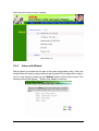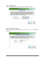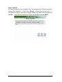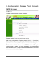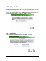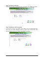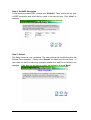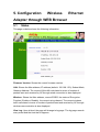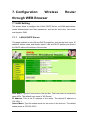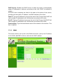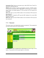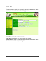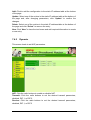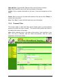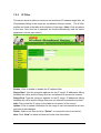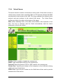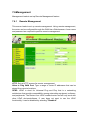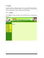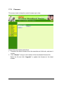
1
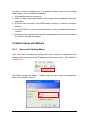
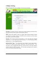
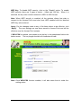
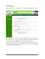
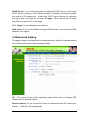
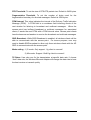
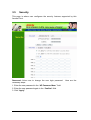
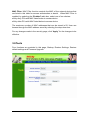
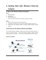
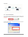
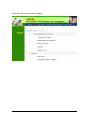
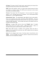
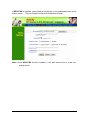
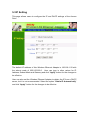
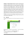
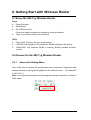
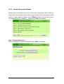
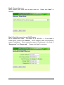
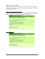
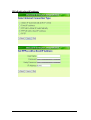
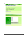
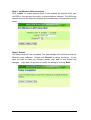
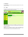
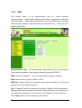
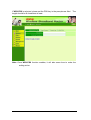
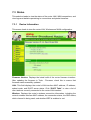
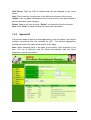
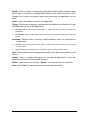
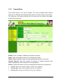
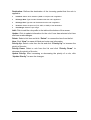
54Mbps Wireless LAN
Pocket Access Point
USER MANUAL
Contents
1.
Overview ....................................................................................................1
1.1
Product Feature ................................................................................1
1.2
System Requirements ......................................................................1
1.3
How to switch within 3 modes...........................................................1
2.
Getting Start with Access Point ...............................................................2
2.1
Know the 54Mbps Wireless Network Access Point...........................2
2.2
Connect to the 54Mbps Wireless Network Access Point ..................2
2.3
Quick Setup with Wizard...................................................................3
2.3.1
Access the Setting Menu .......................................................3
2.3.2
Setup with Wizard ...................................................................4
3.
Configuration Access Point through WEB Browser ..............................8
3.1
Status................................................................................................8
3.2
Basic Setting...................................................................................10
3.3
IP Setting ........................................................................................12
3.4
Advanced Setting............................................................................13
3.5
Security ...........................................................................................15
3.6
Tools ...............................................................................................16
4.
Getting Start with Wireless Ethernet Adapter .......................................18
4.1
Know the Wireless Ethernet Adapter ..............................................18
4.2
Connect to the Wireless Ethernet Adapter......................................18
4.2.1 Access the Setting Menu ........................................................19
4.2.2
Setup with Wizard .................................................................21
5.
Configuration Wireless Ethernet Adapter through WEB Browser ......24
5.1
Status ..............................................................................................24
5.2
Basic Setting ...................................................................................25
5.3
IP Setting ........................................................................................28
5.4
5.5
5.6
Advanced Setting............................................................................29
Security ...........................................................................................30
Tools ...............................................................................................31
6.
Getting Start with Wireless Router ........................................................32
6.1
Know the 802.11g Wireless Router.................................................32
6.2
Connect to the 802.11g Wireless Router ........................................32
6.2.1
Access the Setting Menu .....................................................32
6.2.2
Quick Setup with Wizard ......................................................34
7.
Configuration Wireless Router through WEB Browser........................41
7.1
LAN Setting ....................................................................................41
7.1.1
LAN & DHCP Server ............................................................41
7.1.2
WAN.....................................................................................42
7.1.3
Password .............................................................................43
7.1.4
Time .....................................................................................44
7.2
Wireless.........................................................................................45
7.2.1
Basic ....................................................................................45
7.2.2
WEP.....................................................................................46
7.2.3
Advanced .............................................................................48
7.3
Status.............................................................................................49
7.3.1
Device Information ...............................................................49
7.3.2
Log.......................................................................................50
7.3.3
Log Setting...........................................................................51
7.3.4
Statistic.................................................................................52
7.3.5
Wireless ...............................................................................53
7.4
Routing ...........................................................................................54
7.4.1
Static ....................................................................................54
7.4.2
Dynamic ...............................................................................55
7.4.3
Routing Table .......................................................................56
7.5
Access ............................................................................................57
7.5.1
MAC Filters ..........................................................................57
7.5.2
Protocol Filter.......................................................................58
7.5.3
IP Filter.................................................................................59
7.5.4
Virtual Server .......................................................................60
7.5.5
Special AP............................................................................61
7.5.6
DMZ .....................................................................................63
7.5.7
Firewall Rule ........................................................................64
7.6
Management...................................................................................66
7.6.1
Remote Management ..........................................................66
7.7
Tools ...............................................................................................68
7.7.1
Restart .................................................................................68
7.7.2
Settings ................................................................................69
7.7.3
Firmware ..............................................................................70
7.7.4
Ping Test ..............................................................................71
2
1. Overview
1.1 Product Feature
●
●
●
●
●
●
●
3-in-1 function build-in with easily accessible hot-key switch, including
Access Point, Access Point Client and Wireless Router. It’s also the
smallest networking device in the market.
Low power consumption <less than 460 mA>, and support USB power
adapter which provides the best mobility.
Compliance with IEEE 802.11g and 802.11b standards
Compliance with WiFi standard
Achieving data rate up to 54Mbps for 802.11g and 11Mps for 802.11b with
wide range coverage
Strong network security with WEP encryption, and PWA-PSK function.
Quick and easy setup with Web-based management utility.
1.2 System Requirements
●
●
●
Windows 98SE, Millennium Edition (ME), 2000 and XP operating systems
Microsoft Internet Explorer 5.5 or higher
At least one RJ-45 Ethernet network adapter installed.
1.3 How to switch within 3 modes
●
●
●
3 modes are AP, Client and wireless RT.
Switch to the mode user wants with the hot key, then re-plug the power.
Few seconds later, the device will reboot automatically to the mode user
wants.
●
●
For AP, please use 192.168.1.1 as the default IP to configure the settings.
For Client, please use 192.168.1.50 as the default IP to configure the
settings.
●
For wireless RT, please use 192.168.1.1 as the default IP to configure the
settings, note that the settings must through the wireless connection,
instead of RJ45 cable.
1
2. Getting Start with Access Point
2.1 Know the 54Mbps Wireless Network Access Point
Ports:
● Power Receptor
● Reset Button
● RJ-45 Ethernet Port
Cross-over cable is required to connect to computer directly
LEDs:
● Power LED: ON when the unit is powered up
●
●
LAN LED: ON indicates LAN connection; BLINK indicates LAN activity
WLAN LED: ON indicates WLAN is working; BLINK indicates wireless
activity.
2.2 Connect to the 54Mbps Wireless Network Access Point
Build the Infrastructure Mode
2
In order to setup an Infrastructure of a wireless network such as the example
shown above, user will need the following:
1. A broadband Internet connection.
2. ADSL or Cable modem provided by ISP as part of the broadband connection
installation.
3. A Router that connects to the ADSL/Cable modem for Internet connection
sharing.
4. An Access Point to connect with the Router to form a wireless infrastructure
network.
5. Wireless clients equipped with wireless networking devices such as wireless
PC Card for wireless connection.
2.3 Quick Setup with Wizard
2.3.1
Access the Setting Menu
User could start to access the configuration menu anytime by opening a web
browser window and typing the IP address of this access point. The default IP
is 192.168.1.1.
The below window will popup.
Both of the default is “admin”.
Please enter the user name and password.
3
Now, the main menu screen is popup.
2.3.2
Setup with Wizard
Setup wizard is provided as the part of the web configuration utility. User can
simply follow the step-by-step process to get Access Point configuration ready to
run in 4 easy steps by clicking on the “Wizard” button on the function menu. The
following screen will appear. Please click “Next” to continue.
4
Step 1: Set Password
User can change the password and then click “Next” to continue.
Step2: Set WLAN Connection
Please type the name of SSID and select the channel. Then, click “Next” to
continue.
5
Step 3: Set Wireless LAN Connection
If user doesn’t want to use “default” as the SSID, user can change SSID here.
User can also choose different channel to avoid noise coming from other
wireless networking devices. Please click “Next” to continue.
Step 4: Set WEP Encryption
If user wants to enable WEP, please click “Enabled”. Then, select the key size
of WEP encryption and enter the key value in the key text box. Please click
“Next” to continue.
6
Step 5: Restart
The Setup wizard is now completed. The new settings will be effective after the
Access Point restarted. Please click “Restart” to reboot the Access Point. If
user does not want to make any changes, please click “exit” to quit without any
changes. User also can go back to modify the setting by clicking “Back”.
7
3. Configuration Access Point through
WEB Browser
3.1 Status
This page as below shows the following information.
Firmware Version: Shows the current firmware version.
LAN: Shows the Mac address, IP address (default: 192.168.1.1), Subnet Mask,
Gateway Address. The current LAN traffic calculated in terms of number of
packets sent and received by AP through wired connection is also displayed.
Wireless: Shows the Mac address, current ESSID, the status of Encryption
Function (Enable or Disable), the current using channel. The current wireless
traffic calculated in terms of number of packets sent and received by AP through
wireless communication is also displayed.
8
View Log: Once clicked, the page will change to login page. The login page
records every event and the time that it happens.
User may clear the entries recorded in the log by clicking the “Clear Log” button,
and refresh the screen to show the latest log entries by clicking the “Refresh”
button.
9
3.2 Basic Setting
This is the page allow user to change the access point settings.
AP Name: The name of the AP, which can be used to identify the Access Point
among the all the Access Points in the wireless network.
SSID: Service Set Identifier, which is a unique name shared among all clients
and nodes in a wireless network. The SSID must be identical for each clients
and nodes in the wireless network.
Channel: The channel that AP will operate in. User can select the channel
range from 1 to 11 for North America (FCC) domain, 1 to 13 for European (ETSI)
domain and 1 to 14 for Japanese domain.
Authentication Type: The authentication type default is set to open system.
There are four options: open system; shared key; WPA and WPA-PKS. User
may want to set to Shared Key when the clients and AP in the same wireless
network enable the WEP encryption. All the nodes and hosts on the network
must use the same authentication type.
10
WEP Key: To disable WEP security, click on the “Disable” option. To enable
WEP security, there are 2 types to select – 64bits and 128 bits. When it is
selected, the key value must be entered in ASCII or HEX format.
Note: When WEP security is enabled, all the wireless clients that wish to
connect to the Access Point must also have WEP enabled with the identical
WEP Key value entered.
Apply: For the changes made to any of the items above to be effective, click
“Apply”. The new settings are now been saved to Access Point and will be
effective once the Access Point restarts.
If WPA-PSK is enabled, user needs to set the key in the passphrase field as the
below screen. The key length should be 8 characters at least.
Note: Once WPA-PSK function enables, it will take some time to make the
setting active.
11
3.3 IP Setting
This page allows user to configure the IP and DHCP settings of the Access
Point.
The default IP address of this access point is 192.168.1.1 with the subnet mask
of 255.255.255.0. User can type in other values for IP Address, Subnet Mask
and Gateway and click “Apply” button for the changes to be effective.
User can also set the Access Point to obtain the IP from a DHCP server, but it is
not recommended. Select the option “Obtain IP Automatically” and click “Apply”
button for the changes to be effective.
12
DHCP Server: It is not recommended to enable the DHCP Server if user has a
DHCP server running in LAN network because it probably will cause possible
the conflict of IP assignment. Enable the DHCP server function by selecting
the option “On”, and enter the IP range. IP range : When user set the IP range
that Client can get the IP in the range.
Click “Apply” for the changes to be effective.
DNS server: If User’s local Ethernet support DNS function, user can fix the DNS
address in the space.
3.4 Advanced Setting
This page contains configurations for advanced users, which the change reflects
the wireless performance and operating modes.
AP – The normal Access Point operating mode which forms a wireless ESS
network with its wireless clients.
Beacon Interval: To set the period of time in milliseconds that AP sends out a
beacon. Default is 100 milliseconds.
13
RTS Threshold: To set the size of RTS/CTS packet size. Default is 2432 bytes.
Fragmentation Threshold: To set the number of bytes used for the
fragmentation boundary for directed messages. Default is 2436 bytes.
DTIM Interval: This value indicates the interval of the Delivery Traffic Indication
Message (DTIM). A DTIM field is a countdown field informing clients of the
next window for listening to broadcast and multicast messages. When the
access point has buffered broadcast or multicast messages for associated
clients, it sends the next DTIM with a DTIM interval value. Access point clients
hear the beacons and awaken to receive the broadcast and multicast messages.
SSID Broadcast: While SSID Broadcast is enabled, all wireless clients will be
able to communicate with the access point. For secure purpose, user may
want to disable SSID broadcast to allow only those wireless clients with the AP
SSID to communicate with the access point.
Mode setting : 1) G mode- Only support 11g client to connect!
2) Mix mode- Support 11b&11g client to connect!
TX Rates: User also can fix the transmission at specific data rate, if choose
“Auto” data rate, the Wireless Ethernet Adapter will change the data rate to have
the best receive or transmit quality
14
3.5
Security
This page is where user configures the security features supported by this
Access Point.
Password: Allow user to change the new login password.
necessary steps:
1. Enter the new password in the “AP Password New:” field.
2. Enter the new password again in the “Confirm” field.
3. Click “Apply”
15
Here are the
MAC Filter: MAC Filter function controls the MAC of the network devices that
are listed in this table for access authorization or denial. When MAC Filter is
enabled, by selecting the “Enabled” radio box, select one of two choices:
●Only deny PCs with MAC listed below to access device
●Only allow PCs with MAC listed below to access device
The maximum number of MAC addresses that can be stored is 50. User can
browse through the MAC address saved by selecting the drop-down box.
For any changes made in the security page, click “Apply” for the changes to be
effective.
3.6 Tools
Four functions are provided in this page, Backup, Restore Settings, Restore
default settings and Firmware Upgrade.
16
Backup Settings: Click on “Backup” button, which will open a FileSave Dialog
box, where user gets to save all the current settings and configurations to a file.
Restore Settings: Click on the “Browse” button to open a FileOpen Dialog box,
where user gets to select the file, which saves previous settings and
configurations. Upon selecting the saved file, click “Restore” and complete the
restore process when the access point re-operates after it restarts.
Restore to default settings: Click on “Default” button to restore the access
point back to its manufacture default settings.
Firmware Upgrade: Click on the “Browse” button to open a FileOpen Dialog
box, where gets to select the firmware file, which download from the web for the
latest version. Upon selecting the firmware file, click “Upgrade” and complete
the firmware upgrade process when the Access Point re-operates after it
restarts.
17
4. Getting Start with Wireless Ethernet
Adapter
4.1 Know the Wireless Ethernet Adapter
Ports:
● Power Receptor
● Reset Button
● RJ-45 Ethernet Port
Cross-over cable is required to connect to computer directly
LEDs:
● Power LED: ON when the unit is powered up
●
●
LAN LED: ON indicates LAN connection; BLINK indicates LAN activity
WLAN LED: ON indicates WLAN is working; BLINK indicates wireless
activity.
4.2 Connect to the Wireless Ethernet Adapter
This wireless Ethernet adapter transforms the Ethernet-enabled devices to
have the wireless function. The wireless Ethernet adapter enables wireless
communication over network. There are two examples shown as the below.
Infrastructure Mode:
18
Ad-Hoc Mode:
4.2.1
Access the Setting Menu
User could start to access the configuration menu anytime by opening a web
browser window by typing the IP address of this access point. The default IP is
192.168.1.50.
The below window will popup.
Both of the default is “admin”.
Please enter the user name and password.
19
Now, the main menu screen is popup.
20
4.2.2
Setup with Wizard
Setup wizard is provided as the part of the web configuration utility. User can
simply follow the step-by-step process to get Access Point configuration ready to
run in 4 easy steps by clicking on the “Wizard” button on the function menu. The
following screen will appear. Please click “Next” to continue.
Step 1: Set Password
User can change the password and then click “Next” to continue.
21
Step2: Set WLAN Connection
Please type the name of SSID and select the channel. Click “Next” to continue.
Step 3: Set Wireless LAN Connection
IF user doesn’t want to use “default” as the SSID, user can change SSID here.
Also user can choose different channel to avoid noise coming from other
wireless networking devices. Please click “Next” to continue.
22
Step 4: Set WEP Encryption
If user wants to enable WEP, please click “Enabled”. Then, select the key size
of WEP encryption and enter the key value in the key text box. Click “Next” to
continue.
Step 5: Restart
The Setup wizard is now completed. The new settings will be effective after the
Access Point restarted. Please click “Restart” to reboot the Access Point. If
user does not want to make any changes, please click “exit” to quit without any
changes. User also can go back to modify the setting by clicking “Back”.
23
5. Configuration
Wireless
Ethernet
Adapter through WEB Browser
5.1
Status
This page as below shows the following information.
Firmware Version: Shows the current firmware version.
LAN: Shows the Mac address, IP address (default: 192.168.1.50), Subnet Mask,
Gateway Address. The current LAN traffic calculated in terms of number of
packets sent and received by AP through wired connection is also displayed.
Wireless: Shows the Mac address, current ESSID, the status of Encryption
Function (Enable or Disable), the current using channel. The current wireless
traffic calculated in terms of number of packets sent and received by AP through
wireless communication is also displayed.
View Log: Upon clicked, the page will change to log page. The log page records
every event and the time that it happens.
24
User may clear the entries recorded in the log by clicking the “Clear Log” button,
and refresh the screen to show the latest log entries by clicking “Refresh”
button.
5.2
Basic Setting
This is the page allow to change the settings of access point.
25
AP Name: The name of the AP, which can be used to identify the Access Point
among the all the Access Points in the wireless network.
SSID: Service Set Identifier, which is a unique name shared among all clients
and nodes in a wireless network. The SSID must be identical for each clients
and nodes in the wireless network.
Channel: The channel that AP will operate in. User can select the channel
range of 1 to 11 for North America (FCC) domain, 1 to 13 for European (ETSI)
domain and 1 to 14 for Japanese domain.
Authentication Type: The authentication type default is set to open system.
There are four options: open system; shared key; WPA; WPA-PKS. User may
want to set to Shared Key when the clients and AP in the same wireless network
enable the WEP encryption. All the nodes and hosts on the network must use
the same authentication type.
WEP Key: To disable WEP security, click on the “Disable” option. To enable
WEP security, there are 2 types to select – 64bits and 128 bits. When it is
selected, the key value must be entered in ASCII or HEX format.
Note: When WEP security is enabled, all the wireless clients that wish to
connect to the Access Point must also have WEP enabled with the identical
WEP Key value entered.
Apply: For the changes made to any of the items above to be effective, click
“Apply”. The new settings are now been saved to Access Point and will be
effective once the Access Point restarts.
26
If WPA-PSK is enabled, users need to set the key in the passphrase field as the
below screen. The key length should be 8 characters at least.
Note: Once WPA-PSK function enables, it will take some time to make the
setting active.
27
5.3 IP Setting
This page allows users to configure the IP and DHCP settings of the Access
Point.
The default IP address of this Wireless Ethernet Adapter is 192.168.1.50 with
the subnet mask of 255.255.255.0. User can type in other values for IP
Address, Subnet Mask and Gateway and click “Apply” button for the changes to
be effective.
User can also set the Wireless Ethernet Adapter to obtain the IP from a DHCP
server, but it is not recommended. Select the option “Obtain IP Automatically”
and click “Apply” button for the changes to be effective.
28
5.4 Advanced Setting
This page contains configurations for advanced users, which the change reflects,
the wireless performance and operating modes.
Beacon Interval: To set the period of time in milliseconds that AP sends out a
beacon. Default is 100 milliseconds.
RTS Threshold: To set the size of RTS/CTS packet size. Default is 2432 bytes.
Fragmentation Threshold: To set the number of bytes used for the
fragmentation boundary for directed messages. Default is 2436 bytes.
DTIM Interval: This value indicates the interval of the Delivery Traffic Indication
Message (DTIM). A DTIM field is a countdown field informing clients of the
next window for listening to broadcast and multicast messages. When the
access point has buffered broadcast or multicast messages for associated
clients, it sends the next DTIM with a DTIM interval value. Access point clients
hear the beacons and awaken to receive the broadcast and multicast messages.
29
Preamble: Select Long or Short Preamble type. Preamble is a sequence of bits
transmitted at 1Mbps that allows the PHY circuitry to reach steady-state
demodulation and synchronization of bit clock and frame start. Two different
preambles and headers are defined: the mandatory supported Long Preamble
and header, which interoperates with the 1 Mbit/s and 2 Mbit/s DSSS
specification (as described in IEEE Std 802.11), and an optional Short Preamble
and header (as described in IEEE Std 802.11b). At the receiver, the Preamble
and header are processed to aid in demodulation and delivery of the PSDU. The
Short Preamble and header may be used to minimize overhead and, thus,
maximize the network data throughput. However, the Short Preamble is
supported only from the IEEE 802.11b (High- Rate) standard and not from the
original IEEE 802.11. That means that stations using Short-Preamble cannot
communicate with stations implementing the original version of the protoco
TX Rates: User also can fix the transmission at specific data rate, if choose
“Auto” data rate, the Wireless Ethernet Adapter will change the data rate to have
the best receive or transmit quality.
5.5
Security
This page is where configures the security features supported by Access Point
Client.
Password: Allow to change the new login password.
steps:
Here are the necessary
1. Enter the new password in the “AP Password New:” field.
2. Enter the new password again in the “Confirm” field.
3. Click “Apply”
30
5.6 Tools
Four functions are provided in this page, Backup, Restore Settings, Restore
default settings and Firmware Upgrade.
Backup Settings: Click on “Backup” button, which will open a FileSave Dialog
box, where gets to save all the current settings and configurations to a file.
Restore Settings: Click on the “Browse” button to open a FileOpen Dialog box,
where gets to select the file, which saves previous settings and configurations.
Upon selecting the saved file, click “Restore” and complete the restore process
when the access point re-operates after it restarts.
Restore to default settings: Click on “Default” button to restore the access
point back to its manufacture default settings.
Firmware Upgrade: Click on the “Browse” button to open a FileOpen Dialog
box, where get to select the firmware file, which download from the web for the
latest version. Upon selecting the firmware file, click “Upgrade” and complete
the firmware upgrade process when the Access Point re-operates after it
restarts.
31
6. Getting Start with Wireless Router
6.1 Know the 802.11g Wireless Router
Ports:
● Power Receptor
● Reset Button
● RJ-45 Ethernet Port
Cross-over cable is required to connect to computer directly
● There is no visual LAN port for Pocket AP.
LEDs:
● Power LED: ON when the unit is powered up
● LAN LED: ON indicates LAN connection; BLINK indicates LAN activity
●
WLAN LED: ON indicates WLAN is working; BLINK indicates wireless
activity.
6.2 Connect to the 802.11g Wireless Router
6.2.1
Access the Setting Menu
User could start to access the configuration menu anytime by opening a web
browser window by typing the IP address of this wireless router. The default IP
is 192.168.1.1.
Note: to configure the settings must through the wireless connection, instead of
RJ45 cable.
32
The below window will popup.
Both of the default is “admin”.
Please enter the user name and password.
Now, the main menu screen is popup.
33
6.2.2
Quick Setup with Wizard
Setup wizard is provided as the part of the web configuration utility. User can
simply follow the step-by-step process to get wireless router configuration ready
to run in 6 easy steps by clicking on the “Wizard” button on the function menu.
The following screen will appear. Please click “Next” to continue.
Step 1: Set new Password
User can change the password and then click “Next” to continue.
34
Step2: Choose time zone
Select properly time zone from the drop down list.
continue.
Please click “Next” to
Step 3: Set LAN connection and DHCP server
Set IP address and mask. The default IP is 192.168.1.1.
If user likes to
enable DHCP, please click “Enabled”. DHCP enabled is able to automatically
assign IP addresses. Please assign the range of IP addresses in the fields of
“Range start” and “Range end”. Please click “Next” to continue.
35
Step 4: Set Internet connection
Select how the router will set up the Internet connection: Obtained IP
automatically; Fixed IP address; PPPoE to obtain IP automatically; PPPoE with
a fixed IP address; PPTP.
Obtain IP automatically (DHCP client):
If user wants to enabled DHCP server, choose "Obtain IP automatically (DHCP
client)" to have the router assign IP addresses automatically.
Fixed IP Address:
36
If Fixed IP address is assigned, the below screen will pop up. Please set the
WAN address and DNS server.
PPPoE to obtain IP automatically:
37
PPPoE with a fixed IP address:
38
PPTP:
39
Step 5: Set Wireless LAN connection
Click “enable” to enable wireless LAN. If user enables the wireless LAN, type
the SSID in the text box and select a communications channel. The SSID and
channel must be the same as wireless devices attempting communication to the
router.
Step 6: Restart
The Setup wizard is now completed. The new settings will be effective after the
Wireless router restarted. Please click “Restart” to reboot the router. If user
does not want to make any changes, please click “exit” to quit without any
changes. User also can go back to modify the setting by clicking “Back”.
40
7. Configuration
Wireless
Router
through WEB Browser
7.1 LAN Setting
The screen leads to configure the LAN & DHCP Server, set WAN parameters,
create Administrator and User passwords, and set the local time, time zone,
and dynamic DNS.
7.1.1
LAN & DHCP Server
This page enables to set LAN and DHCP properties, such as the host name, IP
address, subnet mask, and domain name. LAN and DHCP profiles are listed in
the DHCP table at the bottom of the screen.
Host Name: Type the host name in the text box. The host name is required by
some ISPs. The default host name is "AP-Router."
IP Address: This is the IP address of the router. The default IP address is
192.168.1.1.
Subnet Mask: Type the subnet mask for the router in the text box. The default
subnet mask is 255.255.255.0.
41
DHCP Server: Enables the DHCP server to allow the router to automatically
assign IP addresses to devices connecting to the LAN. DHCP is enabled by
default.
All DHCP client computers are listed in the table at the bottom of the screen,
providing the host name, IP address, and MAC address of the client.
Start IP: Type an IP address to serve as the start of the IP range that DHCP will
use to assign IP addresses to all LAN devices connected to the router.
End IP: Type an IP address to serve as the end of the IP range that DHCP will
use to assign IP addresses to all LAN devices connected to the router.
Domain Name: Type the local domain name of the network in the text box. This
item is optional.
7.1.2
WAN
This screen leads to set up the router WAN connection, specify the IP address
for the WAN, add DNS numbers, and enter the MAC address.
42
Connection Type: Select the connection type, either DHCP client, Fixed IP or
PPPoE from the drop-down list.
WAN IP: Select whether to specify an IP address manually, or DHCP to obtain
an IP address automatically. When “Specify IP” is selected, type the IP address,
subnet mask, and default gateway in the text boxes. ISP will provide this
information.
DNS 1/2/3: Type up to three DNS numbers in the text boxes. ISP will provide
this information.
MAC Address: If required by ISP, type the MAC address of the router WAN
interface in this field.
DNS 1/2/3: Type up to three DNS numbers in the text boxes. ISP will provide
this information.
7.1.3
Password
This screen leads to set administrative and user passwords. These passwords
are used to gain access to the router interface.
Administrator: Type the password the Administrator will use to log in to the
system. The password must be typed again for confirmation.
43
7.1.4
Time
This screen leads to set the time and date for the router's real-time clock, select
properly time zone, and enable or disable daylight saving.
Local Time: Displays the local time and date.
Time Zone: Select properly time zone from the drop-down list.
Daylight Saving: Enable or disable daylight saving time. When enabled, select
the start and end date for daylight saving time.
44
7.2 Wireless
This section leads to set wireless communications parameters for the router's
wireless LAN feature.
7.2.1
Basic
This page allow to enable and disable the wireless LAN function, create a SSID,
and select the channel for wireless communications.
SSID: Type an SSID in the text box. The SSID of any wireless device must
match the SSID typed here in order for the wireless device to access the LAN
and WAN via the router.
Channel: Select a transmission channel for wireless communications. The
channel of any wireless device must match the channel selected here in order
for the wireless device to access the LAN and WAN via the router.
45
7.2.2
WEP
This screen leads to set authentication type for secure wireless
communications. Open System allows public access to the router via wireless
communications. Shared Key requires the user to set a WEP key to exchange
data with other wireless clients that have the same WEP key. This router also
supports WPA-PSK.
Authentication Type: The authentication type default is set to open system.
There are three options: Open System; Shared Key and WPA-PKS.
WEP: Enable or Disabled.
This is to make WEP enabled or disabled.
Mode: Select the key mode in ASCII or HEX
WEP Key: Select the level of encryption from the drop-down list. The router
supports, 64- and 128-bit encryption.
Key 1 ~ Key 4: Create an encryption scheme for Wireless LAN transmissions.
Manually enter a set of values for each key. Select which key user wants to use
by clicking the radio button next to the key. Click “Clear” to erase key values.
Click “Apply” button for the changes to be effective.
46
If WPA-PSK is selected, please set the PSK key in the pass phrase field.
length should be 8 characters at least.
The
Note: Once WPA-PSK function enables, it will take some time to make the
setting active.
47
7.2.3
Advanced
This screen leads to configure advanced wireless functions.
Beacon Interval: Type the beacon interval in the text box. User can specify a
value from 1 to 1000. The default beacon interval is 100.
RTS Threshold: Type the RTS (Request-To-Send) threshold in the text box.
This value stabilizes data flow. If data flow is irregular, choose values between
256 and 2432 until data flow is normalized.
Fragmentation Threshold: Type the fragmentation threshold in the text box. If
packet transfer error rates are high, choose values between 256 and 2432 until
packet transfer rates are minimized. (NOTE: set this fragmentation threshold
value may diminish system performance.)
DTIM Interval: Type a DTIM (Delivery Traffic Indication Message) interval in the
text box. User can specify a value between 1 and 65535. The default value is 3.
TX Rates (MBps): Select one of the wireless communications transfer rates,
measured in megabytes per second, based upon the speed of wireless
adapters connected to the WLAN.
SSID Broadcast: While SSID Broadcast is enabled, all wireless clients will be
able to communicate with the access point. For secure purpose, user may
want to disable SSID broadcast to allow only those wireless clients with the AP
SSID to communicate with the access point
48
7.3 Status
This selection leads to view the status of the router LAN, WAN connections, and
view logs and statistics pertaining to connections and packet transfers.
7.3.1
Device Information
This screen leads to view the router LAN, Wireless and WAN configuration.
Firmware Version: Displays the latest build of the router firmware interface.
After updating the firmware in Tools - Firmware, check this to ensure that
firmware was successfully updated.
LAN: This field displays the router's LAN interface MAC address, IP address,
subnet mask, and DHCP server status. Click “DHCP Table” to view a list of
client stations currently connected to the router LAN interface.
Wireless: Displays the router's wireless connection information, including the
router's wireless interface MAC address, the connection status, the SSID status,
which channel is being used, and whether WEP is enabled or not.
49
7.3.2
Log
This screen leads to view a running log of router system statistics, events, and
activities. The log displays up to 200 entries. Older entries are overwritten by
new entries. The Log screen commands are as follows:
Click “First Page” to view the first page of the log
Click “Last Page” to view the final page of the log
Click “Previous Page” to view the page just before the current page
Click “Next Page” to view the page just after the current page
Click “Clear Log” to delete the contents of the log and begin a new log
Click “Refresh” to renew log statistics
Time: Displays the time and date that the log entry was created.
Message: Displays summary information about the log entry.
Source: Displays the source of the communication.
Destination: Displays the destination of the communication.
Note: Displays the IP address of the communication
50
7.3.3
Log Setting
This screen leads to set router logging parameters.
SMTP Server: Type the SMTP server address for the email that the log will be
sent to in the next field.
Send to: Type an email address for the log to be sent to. Click “Email Log
Now” to immediately send the current log.
Syslog Server: Type the IP address of the Syslog Server if user wants the
router to listen and receive incoming Syslog messages.
Log Type: Select what items will be included in the log:
●
System Activity: Displays information related to router operation.
●
Debug Information: Displays information related to errors and system malfunction.
●
Attacks: Displays information about any malicious activity on the network.
●
Dropped Packets: Displays information about packets that have not been transferred
successfully.
●
Notice: Displays important notices by the system administrator.
51
7.3.4
Statistic
This screen displays a table that shows the rate of packet transmission via the
router LAN and WAN ports (in bytes per second).
Click “Reset” to erase all statistics and begin logging statistics again.
52
7.3.5
Wireless
This screen leads to view information about wireless devices that are
connected to the wireless router.
Connected Time: How long the wireless device has been connected to the
LAN via the router?
MAC Address: Displays the devices wireless LAN interface MAC address.
53
7.4 Routing
This selection leads to set how the router forwards data: Static and Dynamic.
Routing Table enables user to view the information created by the router that
displays the network interconnection topology.
7.4.1
Static
It enables user to set parameters by which the router forwards data to its
destination if network has a static IP address.
Network Address: Type the static IP address which network uses to access
the Internet. ISP or network administrator provides this information.
Network Mask: Type the network (subnet) mask for network. If user does not
type a value here, the network mask defaults to 255.255.255.255. ISP or
network administrator provides this information.
Gateway Address: Type the gateway address for network. ISP or network
administrator provides this information.
Interface: Select which interface, WAN or LAN, used to connect to the Internet.
Metric: Select which metric to apply to this configuration.
54
Add: Click to add the configuration to the static IP address table at the bottom
of the page.
Update: Select one of the entries in the static IP address table at the bottom of
the page and, after changing parameters, click “Update” to confirm the
changes.
Delete: Select one of the entries in the static IP address table at the bottom of
the page and click “Delete” to remove the entry.
New: Click “New” to clear the text boxes and add required information to create
a new entry.
7.4.2
Dynamic
This screen leads to set NAT parameters.
NAT: Click the radio buttons to enable or disable NAT.
Transmit: Click the radio buttons to set the desired transmit parameters,
disabled, RIP 1, or RIP 2.
Receive: Click the radio buttons to set the desired transmit parameters,
disabled, RIP 1, or RIP 2
55
7.4.3
Routing Table
This screen leads to view the routing table for the router. The routing table is a
database created by the router that displays the network interconnection
topology.
Network Address: Displays the network IP address of the connected node.
Network Mask: Displays the network (subnet) mask of the connected node.
Gateway Address: Displays the gateway address of the connected node.
Interface: Displays whether the node is connected via a WAN or LAN.
Metric: Displays the metric of the connected node.
Type: Displays whether the node has a static or dynamic IP address
56
7.5 Access
This page leads to define access restrictions, set up protocol and IP filters,
create virtual servers, define access for special applications such as games,
and set firewall rules.
7.5.1
MAC Filters
Allow or deny Internet access to users within the LAN based upon the MAC
address of their network interface. Click the radio button next to “Disabled” to
disable the MAC filter.
Disable: Once the function of MAC filter is disabled, those listed in the MAC
Table are allowed Internet access.
Enable: All users are allowed Internet access except those users in the MAC
Table are deny Internet access.
MAC Table: Use this section to create a user profile which Internet access is
denied or allowed. The user profiles are listed in the table at the bottom of the
page. (Note: Click anywhere in the item. Once the line is selected, the fields
automatically load the item's parameters, which user edited.)
Name: Type the name of the user to be permitted/denied access.
57
MAC Address: Type the MAC address of the user's network interface.
Add: Click to add the user to the list at the bottom of the page.
Update: Click to update information for the user, if user has changed any of the
fields.
Delete: Select a user from the table at the bottom of the list and click “Delete” to
remove the user profile.
New: Click “New” to erase all fields and enter new information.
7.5.2
Protocol Filter
This screen leads to allow and deny access based upon a communications
protocol list which has been created. The protocol filter profiles are listed in
the table at the bottom of the page.
Note: When selecting items in the table at the bottom, click anywhere in the
item. The line is selected, and the fields automatically load the item's
parameters, which user edited:
58
7.5.3
IP Filter
This screen leads to define a minimum and maximum IP address range filter; all
IP addresses falling in the range are not allowed Internet access. The IP filter
profiles are listed in the table at the bottom of the page. (Note: Click anywhere
in the item. Once the line is selected, the fields automatically load the item's
parameters, which user edited.)
Enable: Click to enable or disable the IP address filter.
Range Start: Type the minimum address for the IP range. IP addresses falling
between this value and the Range End are not allowed to access the Internet.
Range End: Type the minimum address for the IP range. IP addresses falling
between this value and the Range Start are not allowed to access the Internet.
Add: Click to add the IP range to the table at the bottom of the screen.
Update: Click to update information for the range if user has selected a list item
and have made changes.
Delete: Select a list item and click “Delete” to remove the item from the list.
New: Click “New” to erase all fields and enter new information.
59
7.5.4
Virtual Server
This screen leads to create a virtual server via the router. If the router is set as a
virtual server, remote users requesting Web or FTP services through the WAN
are directed to local servers in the LAN. The router redirects the request via the
protocol and port numbers to the correct LAN server. The Virtual Sever
profiles are listed in the table at the bottom of the page.
Note: When selecting items in the table at the bottom, click anywhere in the
item. The line is selected, and the fields automatically load the item's
parameters, which user edited.
Enable: Click to enable or disable the virtual server.
Name: Type a descriptive name for the virtual server.
Protocol: Select the protocol (TCP or UDP) used for the virtual server.
Private Port: Type the port number of the computer on the LAN that is being
used to act as a virtual server.
Public Port: Type the port number on the WAN that will be used to provide
access to the virtual server.
60
LAN Server: Type the LAN IP address that will be assigned to the virtual
server.
Add: Click to add the virtual server to the table at the bottom of the screen.
Update: Click to update information for the virtual server if user has selected a
list item and have made changes.
Delete: Select a list item and click “Delete” to remove the item from the list.
New: Click “New” to erase all fields and enter new information.
7.5.5
Special AP
This screen leads to specify special applications, such as games, that require
multiple connections that are inhibited by NAT. The special applications
profiles are listed in the table at the bottom of the page.
Note: When selecting items in the table at the bottom, click anywhere in the
item. The line is selected, and the fields automatically load the item's
parameters, which user edited.
61
Enable: Click to enable or disable the application profile. When enabled, users
will be able to connect to the application via the router WAN connection. Click
Disabled on a profile to prevent users from accessing the application on the
WAN.
Name: Type a descriptive name for the application.
Trigger: Defines the outgoing communication that determines whether the user
has legitimate access to the application.
●
Protocol: Select the protocol (TCP, UDP, or ICMP) that can be used to access the
application.
●
Port Range: Type the port range that can be used to access the application in the text
boxes.
Incoming: Defines which incoming communications users are permitted to
connect with.
●
Protocol: Select the protocol (TCP, UDP, or ICMP) that can be used by the incoming
communication.
●
Port: Type the port number that can be used for the incoming communication.
Add: Click to add the special application profile to the table at the bottom of the
screen.
Update: Click to update information for the special application if user has
selected a list item and have made changes.
Delete: Select a list item and click “Delete” to remove the item from the list.
New: Click “New” to erase all fields and enter new information.
62
7.5.6
DMZ
This screen leads to create a DMZ for those computers that cannot access
Internet applications properly through the router and associated security
settings.
Note: Any clients added to the DMZ exposes the clients to security risks such
as viruses and unauthorized access.
Enable: Click to enable or disable the DMZ.
DMZ Host IP: Type a host IP address for the DMZ. The computer with this IP
address acts as a DMZ host with unlimited Internet access.
Apply: Click to save the settings.
63
7.5.7
Firewall Rule
This screen leads to set up the firewall. The router provides basic firewall
functions, by filtering all the packets that enter the router using a set of rules.
The rules are in an order sequence list--the lower the rule number, the higher
the priority the rule has.
Enable: Click to enable or disable the firewall rule profile.
Name: Type a descriptive name for the firewall rule profile.
Action: Select whether to allow or deny packets that conform to the rule.
Inactive Timeout: Type the number of seconds of network inactivity that
elapses before the router refuses the incoming packet.
Source: Defines the source of the incoming packet that the rule is applied to.
●
Interface: Select which interface (WAN or LAN) the rule is applied to.
●
IP Range Start: Type the start IP address that the rule is applied to.
●
IP Range End: Type the end IP address that the rule is applied to.
64
Destination: Defines the destination of the incoming packet that the rule is
applied to.
●
Interface: Select which interface (WAN or LAN) the rule is applied to.
●
IP Range Start: Type the start IP address that the rule is applied to.
●
IP Range End: Type the end IP address that the rule is applied to.
●
Protocol: Select the protocol (TCP, UDP, or ICMP) of the destination.
●
Port Range: Select the port range.
Add: Click to add the rule profile to the table at the bottom of the screen.
Update: Click to update information for the rule if user has selected a list item
and have made changes.
Delete: Select a list item and click “Delete” to remove the item from the list.
New: Click “New” to erase all fields and enter new information.
Priority Up: Select a rule from the list and click “Priority Up” to increase the
priority of the rule.
Priority Down: Select a rule from the list and click “Priority Down” to
decrease the priority of the rule.
Update Priority: After increasing or decreasing the priority of a rule, click
“Update Priority” to save the changes.
65
7.6 Management
Management leads to set up Remote Management feature.
7.6.1
Remote Management
This screen leads to set up remote management. Using remote management,
the router can be configured through the WAN via a Web browser. A user name
and password are required to perform remote management.
HTTP: Set up HTTP access for remote management.
Allow to Ping WAN Port: Type a range of router IP addresses that can be
pinged from remote locations
UPNP: UPNP is short for Universal Plug and Play that is a networking
architecture that provides compatibility among networking equipment, software,
and peripherals. The Router is an UPnP enabled router and will only work with
other UPnP devices/software. If user does not want to use the UPnP
functionality, it can be disabled by selecting "Disabled".
66
GAMING MODE: If user is experiencing difficulties when playing online games
or even certain applications that use voice data, user may need to enable
Gaming Mode for these applications to work correctly. When not playing games
or using these voice applications, it is recommended that Gaming Mode is
disabled.
67
7.7 Tools
This page leads to restart the system, save and load different settings as
profiles, restore factory default settings, run a setup wizard to configure router
settings, upgrade the firmware, and ping remote IP addresses.
7.7.1
Restart
Click “Restar”t to restart the system in the event the system is not performing
correctly.
68
7.7.2
Settings
This screen leads to save settings as a profile and load profiles for different
circumstances. User can also load the factory default settings, and run a setup
wizard to configure the router and router interface.
VPN Pass-Through: Choose enable or disable on the PPTP or IPSec.
Save Settings: Click to save the current configuration as a profile that user can
load when necessary.
Load Settings: Click “Browse” and go to the location of a stored profile. Click
“Load” to load the profile's settings.
Restore Factory Default Settings: Click to restore the default settings. All
configuration changes user has made will be lost.
69
7.7.3
Firmware
This screen leads to keep the router firmware up to date.
Please follow the below instructions:
1. Download the latest firmware from the manufacturer's Web site, and save it
to disk.
2. Click “Browse” and go to the location of the downloaded firmware file.
Select the file and click “Upgrade” to update the firmware to the latest
release
70
7.7.4
Ping Test
The ping test is to determine whether an IP address or host is present on the
Internet. Type the host name or IP address in the text box and click “Ping” to
start testing.
71
Glossary
Access Point: An internetworking device that seamlessly connects wired and
wireless networks.
Ad-Hoc: An independent wireless LAN network formed by a group of
computers, each with a network adapter.
ASCII: American Standard Code for Information Interchange, ASCII, is one of
the two formats that can use for entering the values for WEP key. It represents
English letters as numbers from 0 to 127.
Authentication Type: Indication of an authentication algorithm which can be
supported by the Access Point:
1. Open System: Open System authentication is the simplest of the available
authentication algorithms. Essentially it is a null authentication algorithm. Any
station that requests authentication with this algorithm may become
authenticated if 802.11 Authentication Type at the recipient station is set to
Open System authentication.
2. Shared Key: Shared Key authentication supports authentication of stations
as either a member of those who knows a shared secret key or a member of
those who does not.
Backbone: The core infrastructure of a network, which transports information
from one central location to another where the information is unloaded into a
local system.
Bandwidth: The transmission capacity of a device, which is calculated by how
much data the device can transmit in a fixed amount of time expressed in bits
per second (bps).
Beacon: A beacon is a packet broadcast by the Access Point to keep the
network synchronized. Included in a beacon are information such as wireless
LAN service area, the AP address, the Broadcast destination addresses, time
stamp, Delivery Traffic Indicator Maps, and the Traffic Indicator Message (TIM).
Bit: A binary digit, which is either -0 or -1 for value, is the smallest unit for data.
Bridge: An internetworking function that incorporates the lowest 2 layers of the
OSI network protocol model.
Browser: An application program that enables one to read the content and
interact in the World Wide Web or Intranet.
BSS: BSS stands for “Basic Service Set”. It is an Access Point and all the LAN
PCs that associated with it.
72
Channel: The bandwidth which wireless Radio operates is divided into several
segments, which we call them “Channels”. AP and the client stations that it
associated work in one of the channels.
CSMA/CA: In local area networking, this is the CSMA technique that combines
slotted time -division multiplexing with carrier sense multiple access/collision
detection (CSMA/CD) to avoid having collisions occur a second time. This
works best if the time allocated is short compared to packet length and if the
number of situations is small.
CSMA/CD: Carrier Sense Multiple Access/Collision Detection, which is a LAN
access method used in Ethernet. When a device wants to gain access to the
network, it checks to see if the network is quiet (senses the carrier). If it is not, it
waits a random amount of time before retrying. If the network is quiet and two
devices access the line at exactly the same time, their signals collide. When the
collision is detected, they both back off and wait a random amount of time
before retrying.
DHCP: Dynamic Host Configuration Protocol, which is a protocol that lets
network administrators manage and allocate Internet Protocol (IP) addresses in
a network.
Every computer has to have an IP address in order to
communicate with each other in a TCP/IP based infrastructure network. Without
DHCP, each computer must be entered in manually the IP address. DHCP
enables the network administrators to assign the IP from a central location and
each computer receives an IP address upon plugged with the Ethernet cable
everywhere on the network.
DSSS: Direct Sequence Spread Spectrum. DSSS generates a redundant bit
pattern for each bit to be transmitted. This bit pattern is called a chip (or
chipping code). The longer the chip, the greater the probability that the original
data can be recovered. Even if one or more bits in the chip are damaged during
transmission, statistical techniques embedded in the radio can recover the
original data without the need for retransmission. To an unintended receiver,
DSSS appears as low power wideband noise and is rejected (ignored) by most
narrowband receivers.
Dynamic IP Address: An IP address that is assigned automatically to a client
station in a TCP/IP network by a DHCP server.
Encryption: A security method that uses a specific algorithm to alter the data
transmitted, thus prevent others from knowing the information transmitted.
ESS: ESS stands for “Extended Service Set”. More than one BSS is configured
to become Extended Service Set. LAN mobile users can roam between
different BSSs in an ESS.
73
ESSID: The unique identifier that identifies the ESS. In infrastructure
association, the stations use the same ESSID as AP’s to get connected.
Ethernet: A popular local area data communications network, originally
developed by Xerox Corp., that accepts transmission from computers and
terminals. Ethernet operates on a 10/100 Mbps base transmission rate, using
a shielded coaxial cable or over shielded twisted pair telephone wire.
Fragmentation: When transmitting a packet over a network medium,
sometimes the packet is broken into several segments, if the size of packet
exceeds that allowed by the network medium.
Fragmentation Threshold: The Fragmentation Threshold defines the number
of bytes used for the fragmentation boundary for directed messages. The
purpose of "Fragmentation Threshold" is to increase the transfer reliability thru
cutting a MAC Service Data Unit (MSDU) into several MAC Protocol Data Units
(MPDU) in smaller size. The RF transmission can not allow to transmit too big
frame size due to the heavy interference caused by the big size of transmission
frame. But if the frame size is too small, it will create the overhead during the
transmission.
Gateway: a device that interconnects networks with different, incompatible
communication protocols.
HEX: Hexadecimal, HEX, consists of numbers from 0 – 9 and letters from A –
F.
IEEE: The Institute of Electrical and Electronics Engineers, which is the largest
technical professional society that promotes the development and application of
electrotechnology and allied sciences for the benefit of humanity, the
advancement of the profession. The IEEE fosters the development of standards
that often become national and international standards.
Infrastructure: An infrastructure network is a wireless network or other small
network in which the wireless network devices are made a part of the network
through the Access Point which connects them to the rest of the network.
ISM Band: The FCC and their counterparts outside of the U.S. have set aside
bandwidth for unlicensed use in the ISM (Industrial, Scientific and Medical)
band. Spectrum in the vicinity of 2.4GHz, in particular, is being made available
worldwide.
MAC Address: Media Access Control Address is a unique hex number
assigned by the manufacturer to any Ethernet networking device, such as a
network adapter, that allows the network to identify it at the hardware level.
Multicasting: Sending data to a group of nodes instead of a single destination.
74
Node: A network junction or connection point, typically a computer or
workstation.
Packet: A unit of data routed between an origin and a destination in a network.
PLCP: Physical layer convergence protocol
PPDU: PLCP protocol data unit
Preamble Type: During transmission, the PSDU shall be appended to a PLCP
preamble and header to create the PPDU. Two different preambles and
headers are defined as the mandatory supported long preamble and header
which interoperates with the current 1 and 2 Mbit/s DSSS specification as
described in IEEE Std 802.11-1999, and an optional short preamble and header.
At the receiver, the PLCP preamble and header are processed to aid in
demodulation and delivery of the PSDU. The optional short preamble and
header is intended for application where maximum throughput is desired and
interoperability with legacy and non-short-preamble capable equipment is not
consideration. That is, it is expected to be used only in networks of like
equipment that can all handle the optional mode. (IEEE 802.11b standard)
PSDU: PLCP service data unit
Roaming: A LAN mobile user moves around an ESS and enjoys a continuous
connection to an Infrastructure network.
RTS: Request To Send. An RS-232 signal sent from the transmitting station to
the receiving station requesting permission to transmit.
RTS Threshold: Transmitters contending for the medium may not be aware of
each other. RTS/CTS mechanism can solve this “Hidden Node Problem”. If the
packet size is smaller than the preset RTS Threshold size, the RTS/CTS
mechanism will NOT be enabled.
SSID: Service Set Identifier, which is a unique name shared among all clients
and nodes in a wireless network. The SSID must be identical for each clients
and nodes in the wireless network.
Subnet Mask: The method used for splitting IP networks into a series of
sub-groups, or subnets. The mask is a binary pattern that is matched up with
the IP address to turn part of the host ID address field into a field for subnets.
TCP/IP: Transmission Control Protocol/ Internet Protocol. The basic
communication language or protocol of the Internet. It can also be used as a
communications protocol in a private network, i.e. intranet or internet. When set
up with direct access to the Internet, computer is provided with a copy of the
TCP/IP program just as every other computer that user may send messages to
or get information from also has a copy of TCP/IP.
75
Throughput: The amount of data transferred successfully from one point to
another in a given period of time.
WEP: Wired Equivalent Privacy (WEP) is an encryption scheme used to protect
wireless data communication. To enable the icon will prevent other stations
without the same WEP key from linking with the AP.
76
Certification Notes
Federal Communication Commission Interference Statement
This equipment has been tested and found to comply with the limits for a
Class B digital device, pursuant to Part 15 of the FCC Rules. These
limits are designed to provide reasonable protection against harmful
interference in a residential installation. This equipment generates,
uses and can radiate radio frequency energy and, if not installed and
used in accordance with the instructions, may cause harmful
interference to radio communications. However, there is no guarantee
that interference will not occur in a particular installation. If this
equipment does cause harmful interference to radio or television
reception, which can be determined by turning the equipment off and on,
the user is encouraged to try to correct the interference by one of the
following measures:
- Reorient or relocate the receiving antenna.
- Increase the separation between the equipment and receiver.
- Connect the equipment into an outlet on a circuit different from that
to which the receiver is connected.
- Consult the dealer or an experienced radio/TV technician for help.
This device complies with Part 15 of the FCC Rules. Operation is subject
to the following two conditions: (1) This device may not cause harmful
interference, and (2) this device must accept any interference received,
including interference that may cause undesired operation.
FCC Caution: Any changes or modifications not expressly approved by
the party responsible for compliance could void the user's authority to
operate this equipment.
IMPORTANT NOTE: FCC Radiation Exposure Statement:
This equipment complies with FCC radiation exposure limits set forth for an
uncontrolled environment. This equipment should be installed and operated
with minimum distance 20cm between the radiator & your body. To maintain
compliance with FCC RF exposure compliance requirements, please avoid
direct contact to the transmitting antenna during transmitting.
This transmitter must not be co-located or operating in conjunction with any
77
other antenna or transmitter.
We declare that the product is limited in CH1~CH11 by specified firmware controlled
in the USA.
78